
API 6D Ball Valve Chinese Manufacturers | Factory Audit Checklist and Quality Comparison Guide
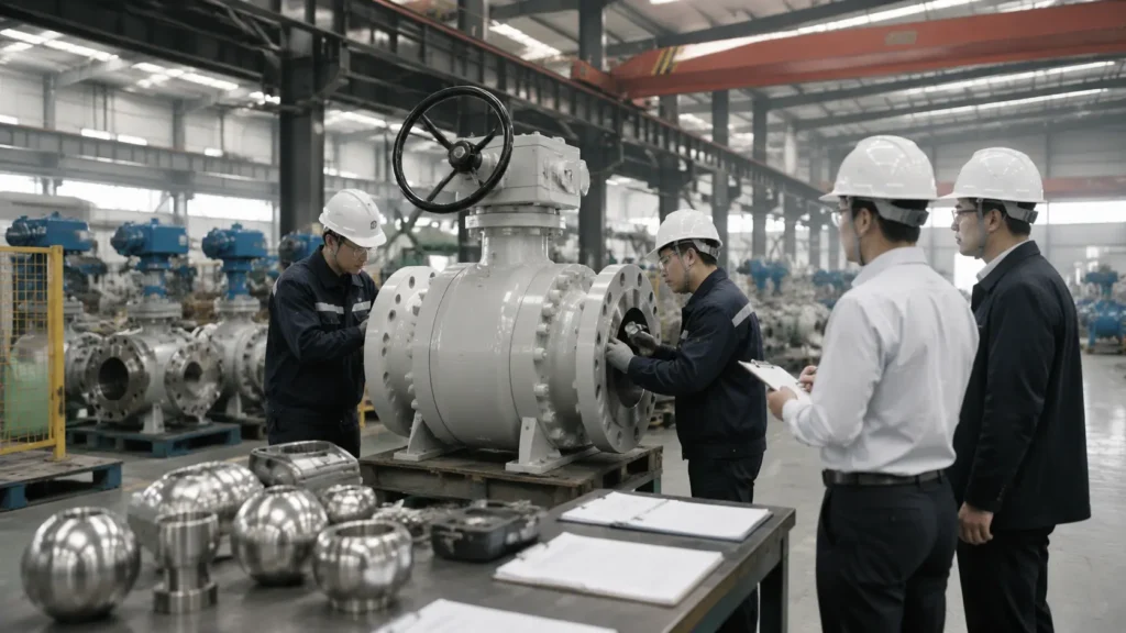
From a Malaysian buyer’s perspective, the 3 most critical things when screening API 6D ball valve suppliers in China are not pricing. The authenticity and scope of the API 6D certificate. Whether the factory controls raw material sourcing, casting, forging, machining, and traceability. Whether NDE, gauge calibration, and non-conformance workflows can be traced to the actual valve batch. For API 6D pipeline ball valve sourcing, market-size numbers are not a qualification basis. The first check should be whether the supplier’s valve manufacturing scope, API Monogram license status, site address, and quoted valve type can be verified against official API information[1][2]. Under these conditions, qualification and line audits become the hard threshold. In our internal audit experience over the past 7 years, this 9-question checklist can quickly screen many obvious authenticity, scope, traceability, and quality-system risks during the first 2 hours of a supplier visit. This checklist is used in our internal sourcing workflow and was refined from more than 100 supplier audit records. It should be treated as a practical buyer-side screening tool, not as an industry-wide statistical survey. Audit Block Verification Item Main Buyer Risk Best Evidence to Request Qualification Audit API 6D certificate authenticity The certificate is fake, expired, suspended, or outside the quoted valve scope. API official lookup result, certificate number, scope, factory address, and matching quotation. Qualification Audit CE/PED coverage The CE mark exists, but the DN range, pressure scope, module, fluid group, material scope, or valve type is not covered. Declaration of Conformity, Notified Body certificate where applicable, conformity assessment module, DN range, pressure scope, material scope, and fluid group. Qualification Audit SIL requirement The supplier claims SIL, but the actual valve package or SIF is not covered. SIL certificate, SIF description, PFDavg calculation, failure rate data, proof test interval, and third-party assessment letter. Production Capacity In-house or outsourced material route The supplier cannot trace pressure-containing parts back to heat number and material records. Approved supplier list, heat traceability records, MTC, PMI report, and incoming inspection records. Production Capacity Machining and grinding capability Critical dimensions, sealing finish, and operating torque cannot be controlled consistently. CMM reports, surface roughness reports, machine accuracy checks, machining route cards, and torque test records. Production Capacity Monthly output Total factory capacity is confused with actual capacity for the same class, size, and design. Capacity by valve type, pressure class, DN size, NDE scope, testing bottleneck, and trial order performance. Quality System NDE personnel qualification NDE reports exist, but personnel qualification, method selection, or traceability is weak. Level II or Level III qualification records, written practice, NDE reports, film numbers, and valve serial numbers. Quality System Gauge calibration management Measurement data is unreliable because instruments are expired, out of tolerance, or outside calibration scope. Gauge ledger, calibration certificates, validity dates, uncertainty, measurement range, and out-of-tolerance procedure. Quality System NCR workflow The factory repairs visible defects but does not trace root cause, affected batches, or recurrence risk. NCR records, 5 Why or fishbone analysis, 8D report, corrective action, preventive action, and closure evidence. The checklist applies most directly to overseas buyers, EPC procurement teams, oil and gas project owners, QA/QC inspectors, and trading companies that need to source API 6D pipeline ball valves from Chinese manufacturers. It is especially useful for Class 600, Class 900, Class 1500, and Class 2500 projects where certificate scope, raw material traceability, pressure testing, NDE records, and final documentation packages directly affect whether the valves can pass owner review or site acceptance. If the project only involves low-pressure utility valves, small brass valves, or non-critical water service valves, not every item in this checklist needs to be treated as a mandatory rejection point. The buyer should match the audit depth with the actual project risk. The most common mistake is treating a supplier’s brochure, price list, or certificate PDF as proof of manufacturing capability. A Chinese maker may have a valid certificate, but the certificate scope may not cover the quoted valve type, pressure class, size range, or actual manufacturing location. A factory may have good sample valves but weak batch traceability. A supplier may claim API 6D experience while outsourcing casting, forging, machining, NDE, assembly, testing, and painting to different subcontractors. Therefore, the audit should not stop at checking whether a factory “has documents”. The real check is whether the certificate, site, process records, test reports, and final valve dossier all point to the same product and the same production batch. Qualification Audit Verify the API 6D Certificate Authenticity The first step is always to verify the certificate number on the API official website, rather than trusting the watermark on the maker’s PDF. You can verify the supplier through the American Petroleum Institute’s official Composite List. The verification status and license scope should be checked live, because API’s online directory provides real-time information for API Monogram licensees and registered organizations[2]. Check the certificate number. Check whether the status is active, suspended, expired, or otherwise restricted. Check the certificate holder name. Check the manufacturing address. Check the product type, pressure class, size range, and scope wording. In one internal high-pressure valve candidate sample reviewed over the past 3 years, we encountered 7 Chinese makers claiming to hold API 6D certificates. Of these 7 cases, 2 had certificate numbers not found in the API official lookup and 1 had an expired unrenewed certificate. This was a small internal sample, not a market-wide failure-rate statistic. On our first factory audit, we once noted a discrepancy between the certificate PDF font and the API standard layout. We demanded that the maker pull up the API online query result on-site, at which point the other party admitted the certificate was “under application”. This step looks like a formality, but it can intercept many false claims in 60 seconds. Our third walkthrough of a Chinese maker in 2023 produced a maker that printed a 6D-1234 certificate, but the API official website showed no record, which was caught on the spot. A useful tip from our team: before traveling to China, we
PTFE vs PEEK vs Metal Seated Ball Valve Seats | Sealing Class, Temperature Limits, and Service Life
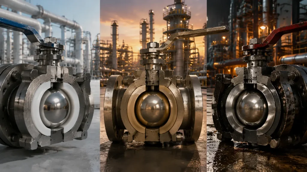
In 2024 we ran a side-by-side comparison of three ball valve seat materials for a refinery client. Side-by-side testing in real refinery service remains one of the most useful ways to check whether published material data, factory leakage tests, and actual seat life point in the same direction. Lab-grade material data and field-grade valve performance can be very different once seat compression, pressure differential, ball rotation, thermal cycling, and media contamination are added. Seat Material Test Service Average Service Life Seat Cost Selection Meaning PTFE 200°C clean steam service 18 months About USD 35 Best for clean media and tight shutoff at or below the qualified valve-seat temperature. PEEK 260°C heat-transfer oil service 30 months About USD 120 Better for many 200 to 260°C services, moderate particles, and applications where PTFE creep is the limiting factor. Stellite 6 hard-faced metal seat 425°C crude service 24 months without leakage beyond the project acceptance limit About USD 280 Necessary when heat, abrasion, coking, pressure drop, or thermal shock exceed polymer seat limits. Across our 12 internal sample batches, selecting the wrong seat material changed total project cost by more than 30% once replacement labor, downtime, spare seats, and actuator changes were included. Published standards remain the baseline for design review and acceptance testing, but the project specification must name the applicable edition and the exact leakage acceptance wording. API Spec 6D defines valve design, manufacturing, testing, documentation, and marking requirements for pipeline valves, while ISO 5208 defines pressure testing and valve closure tightness testing for metallic industrial valves. ASME B16.34 covers pressure-temperature ratings, dimensions, materials, testing, and marking for flanged, threaded, welding-end, wafer, and flangeless valves.[1][2][3] Ball valve seat selection is most difficult in industrial on-off service, especially floating and trunnion mounted ball valves used in refinery, chemical, LNG, oilfield, and high-temperature process lines. The real question is not how PTFE, PEEK, or a metal alloy behaves as a loose material sample. The real question is how the seat behaves after it is compressed into a valve body, loaded by pressure differential, rubbed by the ball, exposed to thermal cycling, and inspected under the leakage requirement written into the purchase specification. The working data below comes from Carilo shop tests, customer site follow-ups, disassembly records, and service cases from 2022 to 2024. These internal service data points are used as engineering benchmarks, not universal guarantees. Service life here means the period before a seat either developed measurable internal leakage beyond the project limit, showed wear deep enough to require seat replacement, or produced torque high enough to trigger actuator review. The final result still depends on valve size, pressure class, media cleanliness, cycling frequency, seat geometry, spring load, actuator sizing, pressure-temperature rating, and the exact leakage standard selected by the buyer. PTFE is usually the first choice for clean media at or below the qualified PTFE valve-seat temperature when tight shutoff is the main requirement. PEEK becomes more useful when PTFE creep, extrusion, heat, or moderate particle damage becomes the limiting factor. Metal seated valves become necessary when temperature, pressure drop, abrasion, coking, or thermal shock exceed what polymer seats can hold. The operator must confirm whether the accepted leakage requirement is ISO 5208, API 6D/API 598 project wording, ANSI/FCI 70-2, IEC 60534-4, or a project-specific test sheet. PTFE Seats Sealing Class PTFE seats are the default choice for many soft seated ball valves because the material can conform to the ball surface and produce very tight shutoff under controlled test conditions. In project documents, “Class VI” is often used as shorthand for very tight shutoff. That wording needs care. ANSI/FCI 70-2 establishes seat leakage classes for control valves, while ISO 5208 and API-type valve test requirements are more common for isolation valves and industrial metallic valves. The Fluid Controls Institute notes that ANSI/FCI 70-2 defines maximum allowable leakage under defined test conditions for control valves; it should not be used to predict leakage at other conditions or as a substitute for an isolation-valve test requirement.[4] For buyers, the important step is to state the exact leakage acceptance criterion instead of only saying “zero leakage.” A safer specification names the standard, edition, test medium, test pressure, holding time, valve size, allowable leakage, and whether the requirement applies to factory acceptance, cryogenic testing, fire-safe testing, or in-service inspection. PTFE has broad chemical resistance, low friction, low thermal conductivity, a density around 2.15 to 2.20 g/cm³, and a melting point around 327°C. NIST polymer property compilations are a more appropriate source for baseline PTFE material data than valve standards or price references.[5] In 2023 we shipped twelve DN50 PTFE seated ball valves to an LNG peak-shaving station. All twelve passed the factory leakage test specified by the buyer, and a six-month site follow-up showed no visible external leakage on any unit. The factory leakage test is necessary but not sufficient. We have seen factory-passed valves leak internally at cryogenic temperature when actual LNG cold shock hits the valve. For cryogenic service, the low-temperature test requirement should be written separately from the normal room-temperature seat leakage requirement. Internal leakage and external leakage must also be kept separate. Internal leakage means media passes across the closed ball and seat into the downstream line. External leakage means media escapes through the stem packing, body joint, end connection, or flange area. PTFE mainly helps the seat-to-ball internal seal. External leakage depends more on packing design, body gasket selection, bolting, flange loading, and installation quality. That is why a valve can pass the seat leakage test but still need separate low-temperature, fugitive-emission, packing, or body-joint verification for the full valve package. PTFE has a very low coefficient of friction compared with most engineering materials, and its low friction is one reason PTFE seats normally require less operating torque than metal seats. A peer-reviewed Macromolecules study describes PTFE as useful in tribological applications because of low friction, high melting temperature, and hydrophobic behavior, while also noting that neat PTFE is prone to high wear and that fillers can improve
Carbon Steel vs Stainless Steel vs Duplex Ball Valves | Material Cost and Performance Trade-Off
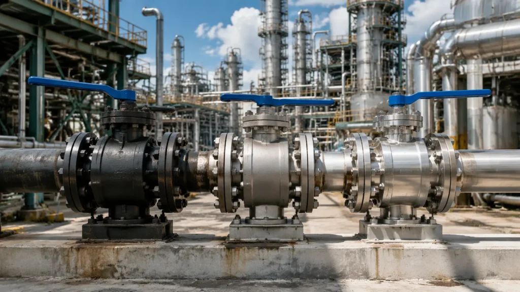
Picking the body material for a pipeline ball valve is a cost-versus-corrosion decision. A wrong choice can wipe out six figures in the field when the medium, water chemistry, temperature or testing scope is not checked early. The real question is not which material is best, but which material fits the medium, chloride level, temperature, pressure class, corrosion allowance and project budget. Across 18 months of Factory Acceptance Test (FAT) witness work for two EPC contractors in Malaysia, I reviewed mill certificates and purchase records for 142 valve bodies. The sample covered ASTM A216/A216M WCB carbon-steel castings[1], ASTM A351/A351M CF8M austenitic stainless-steel castings[2] and ASTM A995/A995M Grade 4A duplex stainless-steel castings for pressure-containing parts[3]. Body Material Records in the 142-Body Sample Observed Normalized Body-Cost Index Minimum Room-Temperature 0.2% Yield Strength Main Trade-Off ASTM A216/A216M WCB 90 bodies, 63.4% 1.0 250 MPa Lowest initial cost, with the greatest need for corrosion control ASTM A351/A351M CF8M 38 bodies, 26.8% 2.6 205 MPa 316-type corrosion resistance at a moderate alloy premium ASTM A995/A995M Grade 4A 14 bodies, 9.9% 4.4 415 MPa About twice the yield strength of CF8M, with better resistance to chloride-related damage The WCB-to-CF8M cost multiple in this sample averaged 1:2.6, while CF8M-to-2205-family duplex averaged about 1:1.7. These are project-specific quoted-cost ratios, not fixed global prices or actual USD-per-kilogram commodity values. Cast Grade 4A provides about 1.7 times the minimum yield strength of WCB and about twice that of CF8M. Higher strength can help reduce selected body sections in an optimized design, but it does not allow the valve wall to be reduced by the same percentage without a full pressure-design check. For pipeline valves, the material decision should be read together with API 6D / ISO 14313 pipeline-valve requirements, ASME B16.34 pressure-temperature rules and the project corrosion basis[4][5][6]. Carbon Steel WCB Lowest Cost WCB is an ASTM A216/A216M carbon-steel casting grade for valves, flanges, fittings and other pressure-containing parts. It is not an abbreviation for “World Class Basic.” In this three-grade comparison, it was normally the least expensive body material. For the 2024 quotations reviewed on a Class 600, DN50, flanged floating ball valve, the normalized body-cost index was approximately: WCB: 1.0 CF8M: 2.6 2205-family duplex: 4.4 The difference was driven by alloy content, casting yield, heat treatment, testing scope, foundry availability and project supply conditions, not only by machining cost. These figures should not be read as USD 1, USD 2.6 and USD 4.4 per kilogram. WCB is often the first candidate for non-corrosive or corrosion-controlled service. Typical screening examples include: Steam and controlled condensate Treated water and hot water with a verified corrosion allowance Dry air and nitrogen Dry hydrocarbon gas above the water dew point Hydrocarbon liquids without a damaging free-water phase ASME B16.34 provides pressure-temperature ratings and construction rules; it does not guarantee a 20-year corrosion life. Service life must be checked using corrosion data, wall allowance, inspection frequency and the project design life. Within the 142-body sample, WCB accounted for 90 bodies, or 63.4% by count, and roughly 38% of the reviewed mixed-size line-item value. This value share came from the actual reviewed purchase records, not from multiplying every body by the DN50 reference price. It confirms WCB’s role as the volume-grade option where corrosion is not the main design driver. I personally witnessed hydrostatic testing on 27 WCB-body valve assemblies. All 27 passed the specified 1.5-times shell-pressure test on the first attempt without body rework. A successful FAT proves pressure-boundary integrity under the specified shop test; it does not prove long-term corrosion resistance in the field. Applicable Media WCB pressure-temperature capability must be read from the applicable ASME B16.34 material group and valve class. Supplier temperature ranges should not be used as a substitute for the class rating, seat design, packing limit, gasket limit and bolting selection. Media that are commonly handled by WCB after engineering review include: Steam and controlled condensate Hot water and treated firewater Compressed air and nitrogen Anhydrous ammonia under a verified material-selection basis Dry hydrocarbon service where liquid water is not expected during operation, startup or shutdown In the 142-body review, the WCB group was used on 27 separate lines. Of these, 21 were steam or water lines, while 6 carried sour hydrocarbons with H2S partial pressure below 0.0003 MPa. The 0.0003 MPa value is a sour-service screening trigger, not a stand-alone approval criterion. ISO 15156 addresses cracking mechanisms caused by H2S, but the engineer must also check whether a water phase is present, plus pH, chloride, temperature, hardness, heat treatment, weld condition and the applicable ISO 15156 limits[7]. WCB requires additional corrosion review, and often a material upgrade, for: Chloride-bearing or oxygenated water Wet sour hydrocarbons Acids and aggressive caustic solutions Stagnant service, dead legs and under-deposit conditions Repeated wet-and-dry cycling An internal liner or coating can be part of a qualified corrosion-control system, but it should not be treated as an automatic substitute for corrosion-resistant alloy. The seat pocket, coating termination and other complex areas are often the hardest locations to prepare and inspect. In the reviewed project records, 4 phenolic-epoxy-coated WCB bodies in water containing about 350 ppm chloride developed coating blistering near the seat area within 30 months. The exposed WCB then showed a reported local attack rate of about 0.8 mm per year, contributing to 4 unplanned shutdowns and more than USD 80,000 in reported production loss. This was a project-specific failure case, not proof that every WCB valve fails at 350 ppm chloride. The correct review must include water chemistry, oxygen, flow, deposits, coating continuity, inspection access and shutdown conditions. Corrosion Limits Carbon-steel corrosion in water does not have one fixed industry rate. Low rates can occur in well-controlled clean water, while much higher rates can occur in oxygenated, contaminated, stagnant or deposit-forming water. The rate should be taken from the project corrosion study or qualified corrosion data, not from the ASTM A216/A216M material specification alone. A chloride value of 200 ppm is not a universal point where the corrosion rate suddenly
Floating Ball Valve vs Trunnion Ball Valve | Cost and Selection Comparison for NPS 2-8 Class 150-600
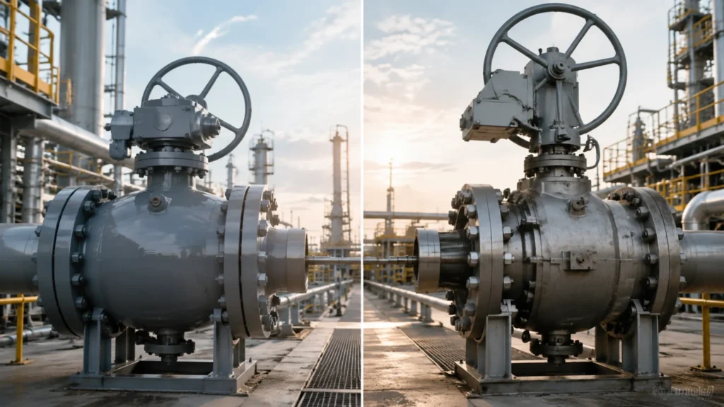
Floating ball valves and trunnion-mounted ball valves can both be used in industrial ball-valve service, but they should not be compared by headline valve price alone. In the NPS 2-8 and ASME Class 150-600 range, the practical cost difference depends on size, pressure class, bore design, body material, seat material, end connection, fire-safe requirement, DBB/DIB requirement, testing scope, and whether a gearbox or actuator is required. A floating ball valve uses a ball that is held mainly by the valve seats. Under line pressure, the ball can move slightly toward the downstream seat to create shutoff. A trunnion-mounted ball valve uses mechanical support at the top and bottom of the ball, so the ball is supported by trunnions or bearing surfaces while the seats move toward the ball. This difference is the main reason floating designs are usually cheaper in small low-pressure sizes, while trunnion designs are often preferred for larger sizes, higher pressure, and automated isolation service[1]. For pipeline valves in oil and gas service, API 6D is commonly used to define requirements for valve design, manufacturing, assembly, testing, documentation, and marking. API 6D is a product specification for pipeline valves; it should not be used as a substitute for project-specific pressure-temperature ratings, seat leakage requirements, actuator sizing, material compatibility, or sour-service material selection[2]. Floating ball valves are usually strongest on first cost in NPS 2-4 Class 150 service. Trunnion-mounted ball valves become more attractive as size, pressure, torque, automation, DBB/DIB isolation, and maintenance risk increase. Selection Area Main Cost Driver Practical Meaning NPS 2-4, Class 150 Simple floating-ball structure, lower part count, lower torque demand Floating-ball valves are usually the lowest acquisition-cost option NPS 2-4, Class 300 Higher differential pressure increases seat load and operating torque Floating-ball valves may still be suitable, but vendor torque data should be checked NPS 6-8, Class 150 Ball size, stem torque, gearbox cost, and actuator margin become more important Compare installed package cost, not bare valve price alone NPS 6-8, Class 300-600 High differential pressure, higher breakaway torque, and higher isolation duty Trunnion-mounted valves are usually the safer default Fire-safe, sour service, DBB/DIB, or high-alloy service Testing, material, documentation, and compliance costs rise Total life-cycle cost matters more than basic valve structure Price Comparison NPS 2-4 Class 150 In small-bore Class 150 service, floating ball valves normally have the clearest acquisition-cost advantage. The design has fewer support components than a trunnion-mounted valve, and the manufacturing route is usually simpler when the valve uses a standard soft-seat configuration. This cost advantage is strongest when the valve is manual, the pressure drop is moderate, the medium is clean, the temperature is within the seat material limit, and the project does not require DBB, DIB, special cavity relief, or high-cycle automation. Cost Item Floating Ball Valve Trunnion Ball Valve Cost Impact Ball support Ball is supported mainly by the seats Ball is mechanically supported by trunnions or bearing surfaces Trunnion structure adds machining and assembly cost Seat system Commonly uses simpler soft-seat construction Commonly uses spring-energized seat assemblies Trunnion seat assemblies add parts and inspection steps Manual operation Usually practical in small Class 150 sizes Usually practical but more expensive as a bare valve Floating design usually wins on first cost Isolation function Standard shutoff unless a special design is ordered DBB, DIB-1, or DIB-2 may be specified Isolation features increase cost but improve safety function ASME Class numbers are pressure-temperature classes, not fixed pressure values. For example, ASME B16.5 flange ratings for carbon steel at 100°F commonly show Class 150 at about 285 psig, Class 300 at about 740 psig, and Class 600 at about 1480 psig. The allowable pressure changes with material group and temperature, so a valve datasheet should always state the applicable pressure-temperature basis instead of treating Class 150, Class 300, or Class 600 as a single pressure value[3]. For valves, ASME B16.34 is also frequently relevant because it covers pressure-temperature ratings, materials, dimensions, testing, and marking for many valve constructions. Soft seats and non-metallic components may impose lower practical limits than the metal pressure-containing body rating, so seat material limits must be checked separately[4]. NPS 6-8 Class 150 When the size increases to NPS 6-8, the cost comparison changes. A floating ball valve may still be cheaper as a bare valve, but the operating torque can force the project to add a gearbox, larger actuator, stronger mounting hardware, or a higher service factor. These added items can narrow or erase the first-cost advantage. Cost Item Why It Changes at NPS 6-8 Procurement Check Bare valve price Floating construction may still cost less than trunnion construction Compare the same NPS, class, bore, body material, seat material, and end connection Gearbox Manual torque may exceed the site’s acceptable handwheel or lever effort Check breakaway torque at maximum differential pressure Actuator Actuator size depends on breakaway torque plus service factor Use the selected manufacturer’s torque table Stem and mounting interface Larger torque may require a stronger stem, bracket, coupling, or ISO mounting pad Confirm actuator interface and safety factor before purchase Maintenance access Large valves are more expensive to remove from the pipeline Compare top-entry, side-entry, split-body, and welded-body construction Published manufacturer torque data show why this size range needs specific verification. One soft-seated floating ball valve torque chart lists NPS 4 Class 150 at 125 N·m, NPS 4 Class 300 at 280 N·m, and NPS 4 Class 600 at 770 N·m. These values are manufacturer-specific, but the engineering pattern is important: torque rises quickly with size and pressure class[5]. For actuator selection, torque tables should be treated as the starting point, not the final actuator size. Actuator sizing guides commonly state that safety factors are not always built into published valve torque values, and that application factors must be considered for actual service conditions[6]. For NPS 6-8 valves, the correct comparison is installed package cost: valve, gearbox, actuator, mounting kit, service factor, testing, and maintenance access. Class 300-600 Service From Class 300 upward, floating ball valve selection becomes more sensitive to
How to Specify a Metal-Seated Ball Valve for High Temperature Service | 400°C+ Material and Design Guide

When process temperature exceeds 400°C, a soft-seated ball valve should not be treated as the default choice. PTFE has a typical continuous service temperature around 260°C, while common PEEK grades are usually rated around 250-260°C for continuous service. At 400°C and above, the valve specification normally moves toward metal-to-metal sealing, high-temperature stem packing, controlled thermal expansion, and verified hot-service torque margin[1][2]. API 6D is an appropriate baseline for pipeline and piping valves because it defines manufacturing-related requirements for valves. It should not be used as the sole source for high-temperature material performance, oxidation rate, coating behavior, or hot leakage behavior. Those items need separate verification through material data sheets, thermal expansion calculations, coating qualification, packing qualification, and project-specific testing[3]. High-Temperature Challenges Thermal Expansion Effects Above 400°C, thermal expansion mismatch between the ball, seat, stem, bonnet, and body can become one of the main causes of torque rise, seat loading change, and leakage. Austenitic stainless steels generally expand more than cast carbon steel. For example, 316L stainless steel has a mean linear thermal expansion coefficient of about 17.5×10⁻⁶/K between 20°C and 400°C, while ASTM A216 cast carbon steel is commonly listed around 12×10⁻⁶/K[4][5]. For a WCB body with a stainless steel ball, the stainless component expands faster during heat-up. The actual clearance change depends on valve size, sealing diameter, seat pocket design, body restraint, pressure load, and the temperature gradient across the valve. In medium and large valves, a rise from ambient temperature to 400°C can create differential movement in the tenths-of-a-millimeter range if the sealing diameter is large enough. This movement may increase operating torque, reduce effective seat load, or create local interference if the seat system has no thermal compensation. Material / Condition Typical Value Engineering Impact 316L stainless steel mean CTE, 20-400°C About 17.5×10⁻⁶/K Higher expansion can tighten or distort the sealing pair ASTM A216 cast carbon steel CTE About 12×10⁻⁶/K Lower expansion can create mismatch against stainless internals Ball-to-seat CTE difference Minimized by material pairing; many designs target below about 3×10⁻⁶/K where practical Reduces sensitivity to thermal cycling, torque rise, and leakage Thermal-growth check Based on actual sealing diameter and metal temperature Prevents relying on nominal process temperature alone For cyclic service above 400°C, the ball-to-seat thermal expansion relationship should be calculated rather than assumed from material grade names. Use the actual metal temperature of the ball, seat, stem, and body, not only the process temperature. Check both hot operating clearance and cold assembly clearance. For trunnion-mounted metal-seated ball valves, include spring travel, seat pocket growth, trunnion alignment, and axial ball movement in the tolerance stack. For frequent start-up and shutdown service, calculate both steady-state thermal growth and transient thermal-gradient effects. ISO 5208 leakage classes are useful for pressure and seat testing, but ISO 5208 uses a test fluid temperature above 5°C and not greater than 40°C. A valve that passes ISO 5208 Rate B at standard test temperature has not automatically been proven to seal at 400°C. For critical high-temperature service, add a hot leakage test or thermal-cycle leakage test to the project specification[6]. Material Oxidation Steam, oxygen, sulfur-bearing media, chlorides, acids, and thermal cycling can accelerate surface degradation at high temperature. Oxide growth depends on alloy chemistry, surface finish, oxygen potential, water vapor, temperature, and exposure time. Research on 316L stainless steel exposed at 400°C, 600°C, and 800°C shows that oxidation behavior changes strongly with temperature and exposure duration, so oxide-thickness values should not be copied into a valve specification unless the test medium and exposure conditions match the application[7]. In metal-seated ball valves, oxidation is not only a wall-thinning problem. Oxide scale, spalled particles, and corrosion debris can enter the ball-to-seat interface and create abrasive leakage paths. Steam oxidation literature also shows that oxide growth and exfoliation become important concerns in high-temperature steam systems, especially as temperature, pressure, and service time increase[8]. Oxidation Condition Expected Result Valve Risk Stainless steel in controlled steam near 400°C Protective oxide may remain stable if chemistry and oxygen potential are controlled Leakage risk increases if oxide breaks away and enters the sealing interface Low-alloy or chrome-moly steel in high-temperature steam Oxide growth and exfoliation must be considered over long service intervals Hard oxide debris can scratch the ball and seat Nickel-chromium or nickel-molybdenum sealing face Often better resistance in corrosive or oxidizing environments Higher initial cost but lower risk of rapid sealing-face degradation Thermal cycling Expansion mismatch between oxide and substrate can promote cracking or spalling Particles can produce leakage tracks and torque instability Do not treat “stainless steel” as a universal high-temperature oxidation solution. Grade, heat treatment, surface finish, and medium chemistry matter. For steam service, evaluate oxide spalling as a leakage and torque risk, not only as a corrosion-rate issue. For sulfur-, chloride-, or acid-bearing media, select the sealing-face material from corrosion data for the actual medium. When specifying an API 6D ball valve for corrosive 400°C+ service, define both the pressure-containing body material and the sealing-face alloy, coating, or hardfacing. In high-temperature steam service, oxide debris can be as important as general corrosion rate because it acts directly on the metal-to-metal sealing interface. Lubrication Failure At 400°C, most conventional greases are outside their safe continuous operating range. Many petroleum-based products degrade far below 400°C. Special PFPE high-temperature lubricants can reach higher limits; Krytox™ XHT products are listed for useful temperature ranges up to 360°C continuous service and temperature spikes up to 400°C when used with suitable metallurgy and periodic relubrication[9]. This does not make ordinary grease lubrication a safe default for a 400°C metal-seated ball valve. Lubrication / Bearing Issue Practical Range or Design Concern Design Response Hydrocarbon grease Normally unsuitable for continuous 400°C friction pairs Avoid as the primary lubrication method PFPE high-temperature grease Special grades may reach 360°C continuous and 400°C short spikes under controlled conditions Use only with product-specific validation and relubrication planning Solid lubricant film or powder Useful where wet lubricants cannot survive Confirm oxidation behavior, replenishment method, and compatibility with the medium Ceramic or hard-coated bearing surfaces Can reduce
How to Manage Valve Spare Parts Inventory for a Petrochemical Plant | Critical Spares Planning
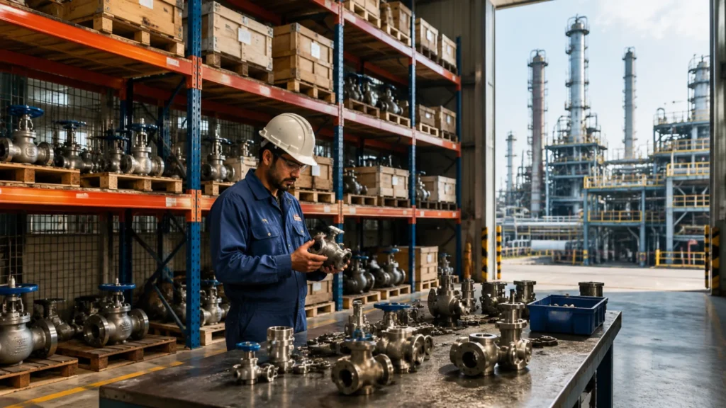
A ball valve spare parts list in a petrochemical plant can easily run into hundreds of material codes once size, pressure class, body material, trim material, seat design, actuator type, and service condition are separated. The parts that decide downtime, however, are usually a much smaller group. Inventory control should begin by separating shutdown-critical parts from ordinary consumables, long-lead insurance spares, and obsolete stock. The most effective spare strategies for refinery, ethylene, PTA, and other petrochemical units are built around risk-based classification rather than purchase value alone. API 570 is useful as an inspection and maintenance reference for in-service piping systems, while ISO 14224 is useful for structuring reliability and maintenance data such as failure mode, failure cause, maintenance action, and repair time. Neither standard is an inventory formula, but both can support disciplined spare-parts planning when combined with plant-specific downtime cost, lead time, consumption history, and approved risk ranking[1][2]. In one internal spare-list optimization project, the planned valve-spare budget was reduced from 8.5 million to 5.8 million yuan, a reduction of about 32 percent. The saving came from removing duplicated non-critical stock, separating routine consumables from long-lead parts, and protecting the spares whose absence could delay restart after maintenance. Any shutdown improvement after such a change should not be attributed to inventory alone; it also depends on maintenance planning, supplier response, inspection findings, operating discipline, and the quality of interchangeability records. Spare parts are not about quantity. They are about never running out of the parts that can stop production. Planning Item Typical Planning Range Meaning for Inventory Control Total ball valve spare material codes Hundreds of codes in a large plant The full spare list must be filtered by criticality, consumption pattern, lead time, and interchangeability. Critical spares share A small minority of total codes in most reviewed lists A limited number of parts usually drives most downtime exposure. Budget reduction in one internal project 8.5 million to 5.8 million yuan About 32 percent lower planned spare budget after duplicate and low-risk stock was removed. Core inventory metrics Critical-part stockout count and shutdown-delay hours Inventory success should be measured by availability risk, not by warehouse value alone. Control basis Risk ranking, consumption history, lead time, and approved supplier capability Financial ABC classification is not enough for petrochemical valve spares. Spare Classification What Counts as Critical Spares Critical spares are not defined by price. They are the parts whose failure can prevent safe operation, delay restart, create unacceptable leakage, or force a process train to remain shut down. A low-cost sealing component in toxic, flammable, high-pressure, sour, hydrogen, or low-emission service can be more critical than an expensive part installed on a non-essential auxiliary line. API 570 covers inspection, rating, repair, and alteration of in-service piping systems. It can help maintenance teams align spare planning with inspection findings and repair windows, but it does not prescribe a universal 8-to-72-hour spare coverage rule. Replacement windows should come from plant turnaround plans, emergency repair procedures, CMMS history, inspection recommendations, and the approved risk matrix for each line or valve position[3]. The following categories often appear on critical lists when installed in high-consequence service: Valve bodies and end connections Balls or other closure members Seats and seat rings Stems, drive keys, and stem-drive components Stem seals, packing sets, and body seals in hazardous or low-emission service These categories should not be assigned the same risk level automatically. A valve body for a 14-inch Class 1500 special-alloy ball valve may have a much longer procurement cycle and higher capital exposure than a packing set. A packing set may still be critical if the valve is in volatile organic compound service, toxic service, hydrogen service, or an isolation position required for safe shutdown. The correct approach is to score each spare by failure consequence, replacement lead time, probability of demand, service severity, and interchangeability. ISO 14224 provides a structured basis for collecting reliability and maintenance data in petroleum, petrochemical, and natural gas facilities. For valve spare planning, it is useful for standardizing fields such as equipment taxonomy, failure mode, failure cause, maintenance action, MTBF, and MTTR. A plant can use those fields to identify which valve positions repeatedly consume seats, packing, gaskets, actuator parts, or special trim[4]. Critical Spare Type Why It Can Be Critical Inventory Priority Valve body Pressure-retaining part; replacement often depends on material grade, pressure class, casting or forging availability, and documentation package. Highest for large, high-pressure, special-alloy valves. Ball or closure member Directly affects shutoff performance, coating integrity, torque, and leakage control. High for isolation valves in shutdown-critical service. Seat or seat ring Wear, erosion, deformation, or coating damage can directly affect sealing performance. High where leakage affects safety, emissions, product quality, or restart. Stem and drive components Failure can stop valve operation and may require disassembly or actuator removal. High for motorized, emergency isolation, high-cycle, or hard-to-access valves. Stem seal, packing, and body seal May be ordinary consumables in low-risk service but critical consumables in hazardous, high-temperature, sour, hydrogen, or low-emission service. Classify by service severity, regulatory impact, and replacement window. The most direct way to identify critical spares is to map the downtime loss curve. Define the credible shutdown or delayed-restart scenario for each valve position. Calculate the direct production loss for that scenario. Convert the loss into an hourly figure by dividing total shutdown loss by shutdown hours. Compare hourly loss with spare lead time, unit price, and probability of demand. Rank each spare by shutdown impact rather than purchase price alone. For example, if a cracked-gas dryer upstream isolation valve delays restart for 48 hours and the direct production loss is 2.6 million yuan, the hourly loss is about 54,167 yuan. A spare that costs 80,000 yuan but prevents a 48-hour restart delay is not expensive in that context; it is a form of production-risk insurance. Consumable Parts List Consumable parts share three traits: predictable use, relatively low unit price, and repeat replacement. On ball valves, consumables usually concentrate in three locations: Packing or stem-seal
Best Ball Valve Manufacturers in China for Oil and Gas Projects: API 6D Supplier Evaluation Guide
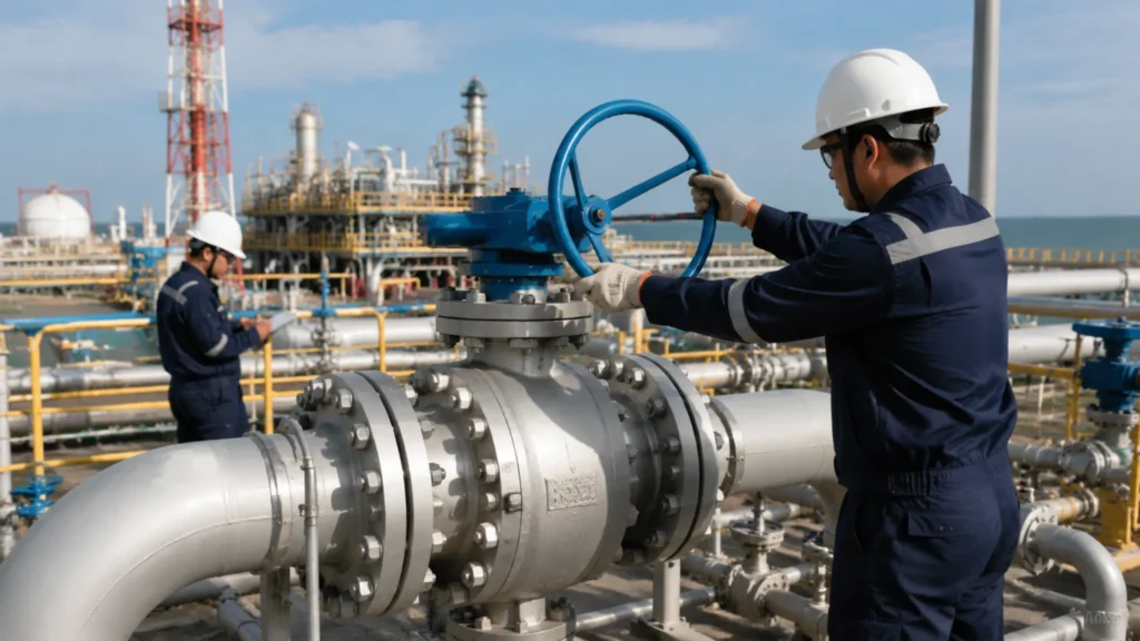
Choosing a ball valve manufacturer in China for oil and gas projects should start with verified qualification, controlled manufacturing capability, relevant project references, and long-term service support. A capable supplier should be able to prove that its quality system, material traceability, machining process, test facilities, documentation control, delivery management, and spare parts system work together in real production. For pipeline, refinery, petrochemical, gas transmission, LNG, and process-industry projects, the strongest procurement decision is not based on one certificate or one low quotation. It should be based on whether the supplier can meet the exact valve type, pressure class, material grade, service condition, inspection level, documentation package, delivery schedule, and after-sales support period required by the project. For oil and gas ball valve procurement, a site audit often reveals more than several rounds of document review. Evaluation Area What It Proves What To Check First Qualification credentials Whether the supplier can meet project entry requirements. API 6D scope, API Monogram license status, ISO 9001 certification, certification body credibility, and project-specific approvals. Factory capability Whether the factory can produce stable, traceable, and testable valves. Material traceability, casting or forging control, CNC machining capability, heat treatment records, inspection records, and test facilities. Project service Whether the supplier can support the order after purchase order placement. Technical response, document control, delivery planning, third-party inspection coordination, spare parts commitment, and field issue handling. Qualification Standards API 6D and API Monogram License Verification API Specification 6D defines requirements for the design, manufacturing, materials, welding, quality control, assembly, testing, marking, documentation, and shipment of valves used in oil and gas applications. The specification covers valve types including ball, check, gate, and plug valves, and is commonly used for projectized oil and gas valve procurement. API 6D covers standard pressure classes including Class 150, Class 300, Class 400, Class 600, Class 900, Class 1500, and Class 2500.[1] For many pipeline, gas transmission, refinery, petrochemical, and EPC projects, API 6D compliance or API 6D Monogram licensing is treated as a practical prequalification requirement by owners, EPC contractors, or end users. It should not be described as a universal legal requirement in every market. API Monogram is a voluntary licensing program that authorizes licensed manufacturers to apply the API Monogram mark to products that meet the applicable API specification. API also states that licensees must demonstrate a quality management system compliant with API Spec Q1.[2] During supplier screening, request the current API 6D license and verify it in the API Composite List. The API Composite List is the official directory for checking API Monogram and APIQR certification information. The key point is not only whether the company appears in the directory, but whether the listed scope covers the required product specification, manufacturing location, valve type, and project requirement.[3] API license status should be checked close to the purchase decision date because license status can change. API states that organizations applying for or holding API Monogram and Repair and Remanufacture licenses must undergo annual audits to verify conformance with API Spec Q1, applicable API product specifications, and program requirements.[4] Search the supplier in the API Composite List. Confirm the licensed company name and manufacturing location. Confirm that API 6D is included in the licensed scope. Check whether the project-required valve type, product specification, and pressure class are covered by the licensed scope. Request quality records that the supplier is allowed to share, including recent inspection and test documentation. Spot-check material certificates, heat numbers, heat treatment records, pressure test reports, and final inspection records for recent production batches. A serious supplier should not resist reasonable verification. If a factory claims that its API license is under renewal, ask for written evidence and verify the current status in the official API directory before awarding the order. ISO 9001 and Certification Body Credibility ISO 9001:2015 is a baseline quality management system standard, but holding a certificate does not prove that the system is effectively implemented on the shop floor. ISO 9001 defines requirements for a quality management system and supports consistent delivery of products and services that meet customer and applicable statutory and regulatory requirements.[5] ISO states that it does not perform certification or issue ISO certificates. Certification is performed by external certification bodies. Buyers should therefore check whether the certification body is accredited and whether the certificate can be verified through the relevant certification body, accreditation body, or recognized certificate database.[6] IAF CertSearch helps users validate whether a certification is valid, whether the certification body is accredited, and whether the accreditation body is an IAF MLA signatory. It is a useful tool when checking supplier management system certificates, especially when the certification body is unfamiliar to the buyer.[7] IATF 16949 should not be treated as a general accreditation body. It is an automotive-sector quality management standard for organizations in the global automotive industry, not a substitute for ISO 9001 certificate verification in oil and gas procurement.[8] Request the ISO 9001 certificate and the latest available surveillance audit evidence. Confirm the certification body name, accreditation mark, certificate number, scope, address, and validity period. Verify the certificate through IAF CertSearch, the certification body, or the relevant national accreditation body. Compare the certificate scope with the actual factory activity, product range, and manufacturing location. Check whether nonconformities have documented root-cause analysis, corrective actions, and closure records. Compare audit records with actual production records, inspection logs, calibration records, and material traceability files on the shop floor. ISO 9001 alone does not prove product capability. For oil and gas ball valves, stronger evidence is a working quality system that controls materials, machining, welding, heat treatment, assembly, testing, preservation, packing, and documentation. Export Track Record and Project Relevance Export experience should be judged by market relevance, not only by shipment volume. A supplier with strong Middle East references may still lack hands-on experience with Southeast Asian offshore, refinery, or coastal petrochemical requirements. A supplier with Southeast Asia experience may still lack approval experience for a national oil company project in the Gulf region. For H2S-containing production environments, material
How to Write a Valve ITP (Inspection and Test Plan) | Hold Points, Witness Points, and Review Points
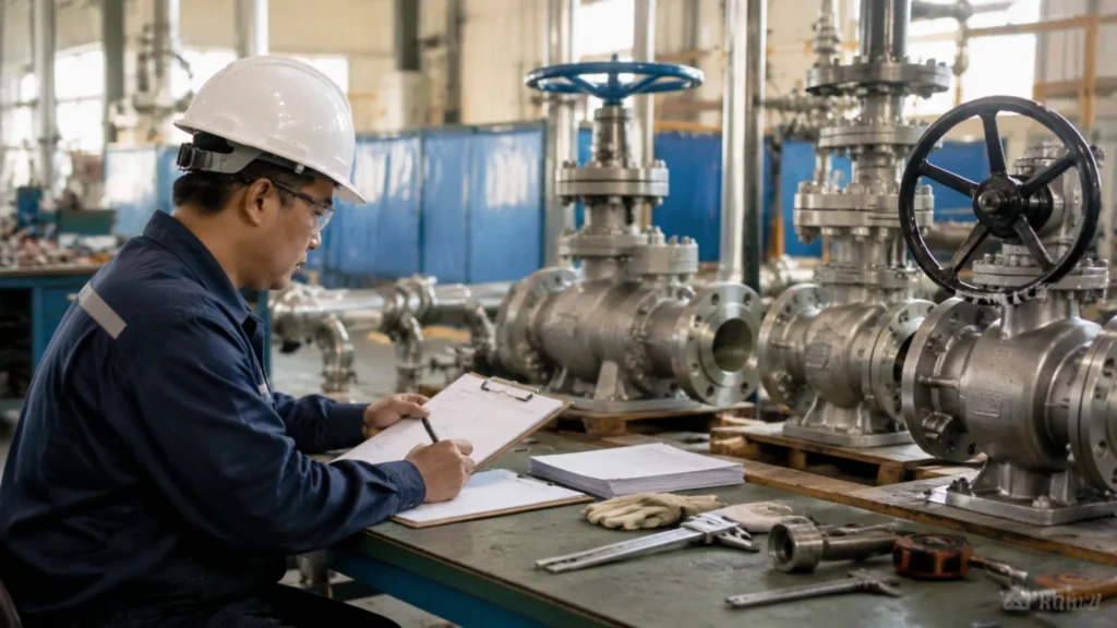
An ITP (Inspection and Test Plan) is a project quality control document used to define inspection activities, test requirements, acceptance criteria, responsible parties, and release rules before valve manufacturing begins. In most valve procurement projects, the manufacturer or vendor prepares the ITP based on the purchase order, project specification, applicable standards, and purchaser inspection requirements. The document is then submitted to the purchaser, owner, end user, or authorized third-party inspection agency for review and approval. A practical valve ITP should not only list inspection stages. It should also define when production must stop, when the inspector must be notified, which records must be reviewed, and what evidence is required before the valve can proceed to the next operation. ISO 10005 provides guidance for quality plans and is a useful reference when preparing project-specific quality control documents[1]. Inspection Point Control Strength Release Rule Hold Point (H) Highest Work cannot proceed until the defined party has inspected, accepted, and released the activity. Witness Point (W) Medium The manufacturer notifies the inspector before the activity. If attendance is waived or the inspector does not attend within the agreed notice rule, work may proceed only if the approved ITP allows it and complete records are retained. Review Point (R) Document control Records are submitted for review, confirmation, and archiving according to the approved document review scope. ITP Fundamentals Three Inspection Point Types Valve ITPs commonly use Hold Points, Witness Points, and Review Points to classify inspection control. The exact wording and authority should always be defined in the approved ITP, contract, and project specification. General definitions of hold and witness points are also widely used in construction and quality control procedures, where a hold point prevents work from continuing without authorization, while a witness point gives the designated party the opportunity to attend after notification[2]. Hold Points (H): A hold point is a mandatory stop. The manufacturer cannot continue past the defined operation until the responsible party has verified the activity and released it. Hold points are normally used where the activity is safety-critical, code-critical, not easily repeatable, or difficult to inspect after the next manufacturing step. Witness Points (W): A witness point is a planned inspection opportunity. The manufacturer must notify the responsible inspector within the agreed notice period. If the inspector attends, the activity is witnessed and recorded. If attendance is waived or no attendance occurs within the agreed rule, continuation is allowed only when the approved ITP permits it and objective evidence is retained. Review Points (R): A review point is a document-control milestone. Records such as MTCs, welding records, NDE reports, calibration certificates, pressure test reports, dimensional reports, and NCR close-out evidence are submitted for review and retention. ISO 9001:2015 defines quality management system requirements and emphasizes controlled operation, documented information, nonconforming output control, and corrective action. It does not prescribe a fixed valve ITP format, but it supports the need for controlled production, evidence of conformity, and traceable release records[3]. The selection of H, W, and R points should be based on manufacturing risk, valve design, pressure class, material criticality, service condition, project specification, and purchaser inspection requirements. API 6D is widely used for pipeline valves and defines manufacturing requirements for pipeline valve products[4]. For API 6D pipeline ball valves, the ITP should also align with the valve data sheet, approved drawings, quality plan, and purchaser inspection assignment. Pressure boundary tests are commonly controlled as H Points in critical oil and gas valve projects because failed results directly affect release. Material receiving inspection may be controlled as W, R, or H depending on material criticality, traceability risk, and contract requirements. Document review points should be strong enough to verify traceability but should not replace mandatory physical inspection when the approved ITP requires on-site release. Further reading: API 6D High-Pressure Ball Valve Standard page. Where H Points Should Stop the Process Any manufacturing step that can permanently affect pressure integrity, sealing performance, material traceability, or in-service safety should be evaluated for H Point control. Hold points should be used carefully. They are powerful quality control gates, but excessive hold points can delay production because each one requires formal release before the next operation begins. Hold points are most useful when the result cannot be fully verified later, when the cost of rework would be high, or when the activity directly affects pressure boundary safety. For valve manufacturing, common H Point candidates include shell hydrostatic testing, final seat testing where required by the purchaser, critical welding repair release, post-repair pressure testing, and final inspection before shipment. Material release before machining may also be assigned as an H Point for special alloys, low-temperature service, sour service, or end-user-critical applications. A common failure mode occurs when a supplier performs a hold-point activity and then continues assembly before the owner or third-party inspector arrives. Once the valve is assembled, it may become difficult to confirm whether the required test was performed under the correct pressure, duration, medium, calibration condition, and acceptance criteria. In that situation, the purchaser may require re-testing, additional witness inspection, or formal concession review. Common H Point Reason for Holding Typical Requirement Shell hydrostatic test Confirms pressure boundary strength For many steel and alloy valves, API 598 and ASME B16.34 are commonly referenced for shell test requirements. ASME B16.34 covers pressure-temperature ratings, materials, nondestructive examination requirements, testing, and marking for applicable valve types[5]. The exact test pressure, hold time, and acceptance criteria should be confirmed against the applicable standard edition and project specification. Low-pressure closure test Confirms seat sealing performance before release API 598 covers inspection, examination, supplementary examinations, and pressure test requirements for several valve types, including ball, gate, globe, plug, check, and butterfly valves[6]. For many steel and alloy valves, industry summaries commonly list low-pressure closure testing at 80 +/- 20 psig and high-pressure closure testing based on 110% of the applicable pressure basis, but final values must be checked against the purchased official standard and project requirements[7]. Critical welding repair release Prevents nonconforming pressure-retaining repair from being
How to Interpret a Valve Pressure Test Report | API 598 Shell and Seat Test Acceptance Criteria

During valve procurement, factory acceptance testing, turnaround inspection, or pre-shipment review, the valve pressure test report is one of the most important quality documents. A report that looks complete at first glance may still contain wrong test pressure, insufficient hold time, unclear test direction, unsuitable test medium, or an incorrect leakage acceptance criterion. This is especially important for valves used in petrochemical plants, LNG terminals, refineries, natural gas pipelines, chemical units, offshore platforms, and other pressure-containing systems. If the pressure test report is read incorrectly, a valve with an incomplete or invalid test may enter site installation and create later rework, schedule delay, leakage risk, or acceptance dispute. Reading a valve pressure test report correctly is not only a paperwork task. It directly affects inspection efficiency, schedule control, procurement compliance, and pressure boundary safety. A reviewable valve pressure test report should clearly identify the applicable standard, standard edition, valve type, pressure class, nominal size, tag number, body material, seat material, shell test, backseat test where applicable, closure test, test medium, test temperature, hold time, leakage result, gauge calibration status, test date, inspector approval, and final acceptance status.[1] Report Item What to Check Why It Matters Standard basis API 598, API 6D, ASME B16.34, ISO 5208, project specification, purchase order, and edition used A wrong standard reference can change test pressure, test duration, leakage rate, and acceptance logic. Shell test Shell test pressure, test medium, test temperature, visible leakage, and pressure boundary condition The shell test verifies the integrity of the valve body, bonnet, cover, and other pressure-containing parts. Backseat test Whether the valve has a backseat feature, test pressure, test medium, hold time, and leakage result Backseat testing applies only to valves with a backseat feature and should not be confused with seat closure testing. Seat / closure test High-pressure closure test, low-pressure closure test, test direction, seat type, and allowable leakage rate The closure test verifies whether the closed valve can isolate the flow path according to the applicable acceptance criterion. Hold time Minimum duration according to valve size and test type Short hold time can hide slow leakage and make a test record invalid. Test record Pressure-time record, calibrated gauge or recorder, gas or liquid source, test date, and inspector signature A complete record makes the result traceable, defensible, and easier to verify during audit or dispute. Pressure Test Standards API 598 vs API 6D Differences API 598, Valve Inspection and Testing, is a valve inspection and pressure testing standard. It covers inspection, examination, supplementary examination, shell tests, backseat tests, low-pressure closure tests, high-pressure closure tests, double block and bleed high-pressure closure tests, visual examination, and high-pressure pneumatic shell tests for valve types within its scope.[1] API Specification 6D, currently titled Specification for Valves, is a broader product specification used for valves in petroleum and natural gas applications. It addresses manufacturing-related requirements and should be read together with the purchase specification, inspection and test plan, and any project-specific testing clauses.[2] The distinction matters because a report may state “tested according to API 6D,” while the actual pressure test parameters may be taken from API 598 or from a project-specific inspection procedure. The report reviewer should not stop at the standard name. The reviewer should check the actual test table, valve type, pressure class, valve size, seat type, test pressure, test direction, hold time, and leakage acceptance basis. Standard Main Purpose How It Is Used in Valve Reports API 598 Valve inspection and pressure testing Used for shell tests, backseat tests, closure tests, test pressures, minimum test duration, test medium, and leakage acceptance. API 6D Valve product specification Used for valve design, manufacture, assembly, testing, documentation, marking, and quality requirements for valves covered by the specification. ASME B16.34 Valve design and pressure-temperature rating standard Used to confirm pressure-temperature ratings, materials, testing, marking, and related design requirements for flanged, threaded, and welding-end valves.[3] ISO 5208 Pressure testing of metallic industrial valves Used when the contract or valve product standard cites ISO pressure testing and closure tightness requirements.[4] API 598 applies mainly to testing by the valve manufacturer or at a mutually agreed facility. API 6D is broader and should not be treated as a substitute for checking the actual pressure test requirements. The purchase order and approved inspection and test plan should state which standard controls if requirements differ. API 598 11th Edition was published in 2023. Some older valve reports still cite previous editions. The inspector should confirm the applicable edition because edition differences may affect terminology, optional tests, documentation, and interpretation of acceptance requirements.[1] Shell Test Pressure The shell test verifies whether the valve pressure boundary can withstand the required test pressure without visually detectable leakage through the pressure boundary walls or fixed body joints. For API 598, shell test pressure depends on valve material, valve type, pressure class, and applicable rating basis. For steel and nonferrous alloy flanged or butt-weld valves covered by API 598, the hydrostatic shell test pressure is generally based on 1.5 times the pressure rating at 38°C / 100°F, rounded to the next higher bar or 25 psig according to the applicable requirement. The pressure rating itself is normally checked against ASME B16.34 or the product standard referenced by the purchase specification.[1] For example, a Class 600 carbon steel ball valve has a pressure rating near 10.2 MPa at 38°C / 100°F depending on the applicable material group and rating table. A hydrostatic shell test pressure around 15.3 MPa to 15.5 MPa is therefore a reasonable order of magnitude. The exact value must still be calculated from the actual material, pressure class, end connection, and standard table used by the project. The test pressure should match the applicable pressure-temperature rating, not a copied value from another valve class. The valve size, pressure class, body material, end connection, and design standard should be checked before accepting the test pressure. For gray iron and ductile iron valves, API 598 gives specific shell test pressure values rather than simply applying the same steel valve calculation
How to Design a Double Block and Bleed Valve Assembly for Safe Isolation and Bleed Verification
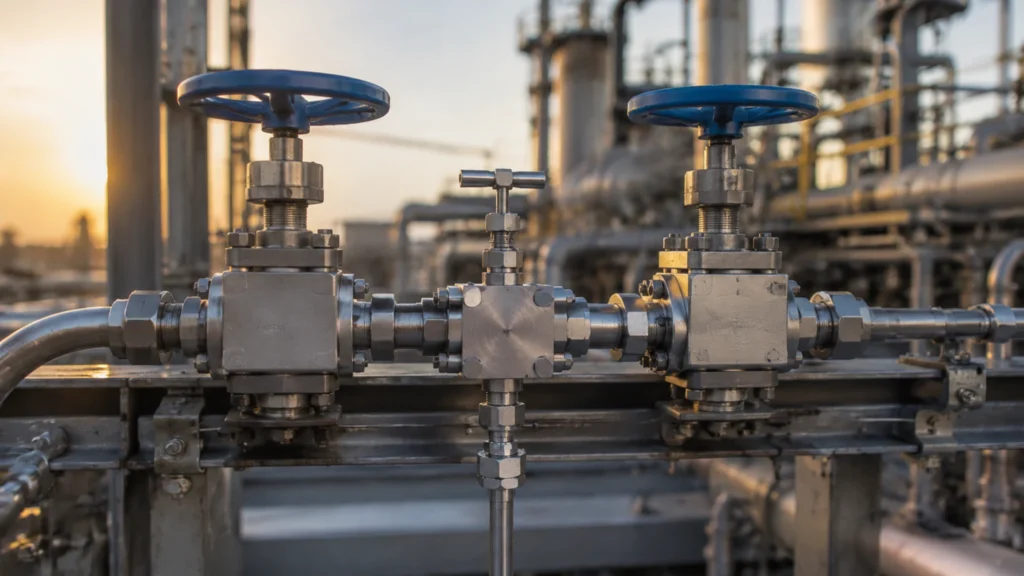
Three DBB valve banks at one petrochemical plant failed to vent completely because the bleed connection was routed to a higher discharge header without proper drain consideration. The problem was not only the valve selection. The bleed line geometry created liquid holdup and made pressure verification unreliable. A DBB valve assembly must be designed as a connected isolation system. The valve body, seat configuration, bleed port, vent routing, discharge destination, pipe support, operating access, and pressure test procedure all affect whether the assembly can isolate, depressurize, and verify leakage safely.[1] DBB design is not only a valve selection issue. It is also a piping layout, vent routing, operation access, and maintenance planning issue. Design Area Main Question Typical Risk If Ignored Isolation principle Does the service require DBB, DIB-1, DIB-2, or two separate block valves? Wrong isolation logic or false leakage verification Bleed port location Should the cavity have a high-point vent, low-point drain, or both? Gas pocket, liquid holdup, blocked bleed path, or trapped pressure Pipe rack layout Is there enough space for operation, support, lifting, and maintenance? No wrench clearance, poor access, actuator removal difficulty, or support overload Bleed destination Where does the vented or drained medium go? Unsafe atmospheric release, backpressure, environmental noncompliance, or blocked discharge Inspection and testing How are the seats, cavity, bleed valve, and final assembly tested? Incomplete pressure verification, unproven bleed function, or poor traceability DBB Principle Single-Body DBB and DIB Implementation A single-body DBB valve places the required sealing elements and an intermediate bleed path inside one valve body. For API 6D pipeline valve service, the project data sheet should clearly state whether the required function is DBB, DIB-1, or DIB-2, because these terms are not interchangeable.[2] A compact DBB manifold normally reduces installation length and external leak points compared with two separate inline block valves. However, compact construction does not automatically prove the required isolation class. The seat design, pressure direction, cavity venting path, test method, and manufacturer documentation must match the process safety requirement. Close the upstream block element. Close the downstream block element. Open the intermediate bleed valve to depressurize the cavity and verify whether either sealing face is leaking. API 6D specifies requirements for manufacturing, assembly, testing, and documentation of pipeline valves. ISO 14313:2025 supplements API 6D, 25th edition, and applies to axial, ball, check, gate, and plug valves for oil and gas pipeline transportation systems within the stated class range.[3] Trunnion-mounted ball valve designs are common for high-pressure and larger-size pipeline DBB or DIB applications because the ball position is mechanically supported and the seat/cavity arrangement can be engineered for defined pressure directions. Floating ball DBB designs may exist in small-bore or special configurations, but they should not be treated as equivalent without checking the seat arrangement and test certificate. The important engineering question is not simply whether the valve is floating or trunnion-mounted. The important question is whether the valve provides the required sealing surfaces, the required pressure barrier direction, and a verifiable intermediate bleed path. Do not use DBB and DIB as interchangeable labels. Confirm whether the seat design seals from one direction or both directions. Confirm whether pressure trapped in the cavity can be safely relieved. Record the required isolation category directly in the valve data sheet. Make the pressure test procedure match the specified isolation category. Bleed valves are commonly selected from needle, ball, or plug designs. Bleed Valve Type Best Use Selection Note Needle valve Instrument isolation, sampling, and controlled bleed Good for small-flow bleeding and gradual depressurization Ball valve General vent and drain isolation duty Simple operation and wide availability Plug valve Dirty, waxy, or solids-bearing service Often more tolerant of contaminated media than small-bore ball valves For abrasive, waxy, or dirty service, the bleed valve should be selected according to solids content, particle size, viscosity, valve bore, expected operation frequency, flushing method, and replacement access. A fixed wear-resistance multiplier should not be used unless it comes from a project-specific test or manufacturer qualification report. ASME B16.34 is relevant when reviewing valve pressure-temperature ratings, materials, dimensions, tolerances, nondestructive examination requirements, testing, and marking for flanged, threaded, and welding-end valves.[4] Further reading: CARILO DBB Compact Manifold Product Page. Two-Valve Tandem DBB Arrangement A two-valve tandem DBB arrangement uses two independent block valves installed in series, with a bleed or drain connection installed in the intermediate spool piece. This arrangement is common when the operator wants two physically separate block valves or when the project isolation philosophy requires two independent inline valves. The two-valve tandem arrangement is often selected when the two block valves belong to different process areas, when spare-part independence is important, or when the plant prefers standard inline valves instead of a compact manifold. Flexible component procurement Independent replacement of either block valve Possible use of different valve types where process conditions require it Clear physical separation between the two isolation valves Easy visual understanding for operations and maintenance teams The main disadvantages are larger footprint, more flanged or welded joints, more potential leak points, and a trapped intermediate spool volume. ASME B16.10 covers face-to-face and end-to-end dimensions of straightway valves and is relevant when comparing the installation length of separate inline valves against a compact DBB manifold.[5] Configuration Typical Length Basis Main Layout Impact Two-valve tandem arrangement Two standard valve face-to-face lengths plus spool, gasket, bolting, branch, and access allowance Longer pipe rack space and more external joints Single-body DBB manifold Manufacturer-specific compact body length Shorter footprint and fewer external joints in many small and medium sizes In congested pipe racks, offshore modules, and packaged skids, the extra length of a tandem arrangement can increase pipe support demand, skid frame size, lifting envelope, and maintenance access requirements. The cost impact should be calculated from the actual layout, not from a fixed cost per square meter. The intermediate spool can also become a dead zone. With both block valves closed, leaked or trapped media remains in the spool until the bleed valve is opened. Depending on bore size and
