
ENGINEERED FLOW CONTROL · CARILO
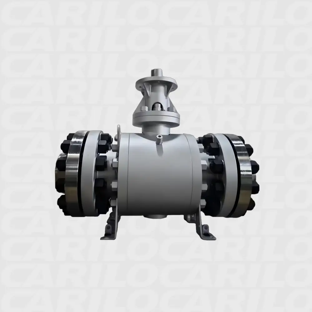
Forged Metal-Seated Trunnion-Mounted Ball Valves
High-integrity shutoff for high-temperature, high-pressure and
abrasive pipeline service. Solid forged trunnion-supported balls
reduce operating torque, while engineered metal seats provide
durable isolation in demanding duty.
Project drawings, material certificates, inspection records and pressure-
test reports can be prepared against the approved valve data sheet.
HOW THE VALVE WORKS
Pressure-supported motion. Metal-to-metal isolation.
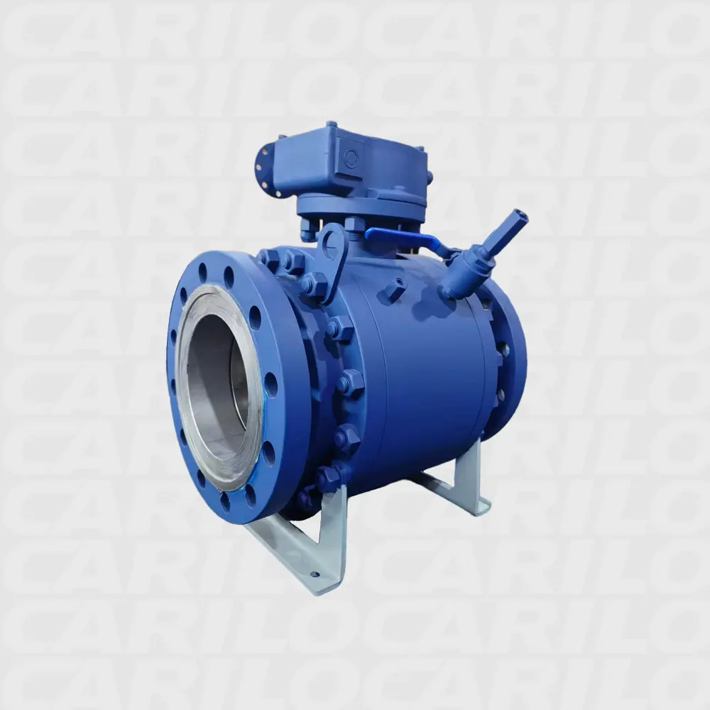
Trunnion-supported forged ball
The fixed shaft system carries the main pressure load, limits ball displacement and helps stabilize operating torque at large sizes and high pressure classes.
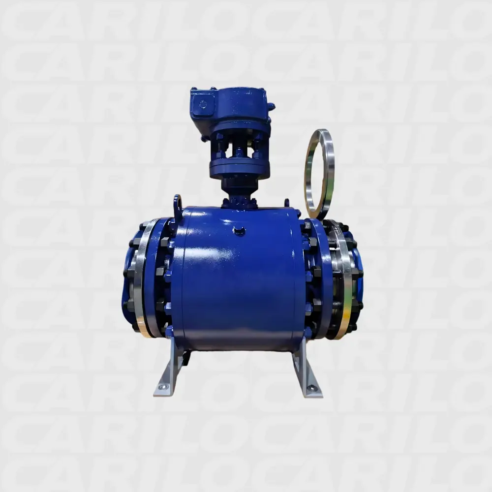
Support the pressure load
Upper and lower trunnions retain the solid forged ball. Pipeline pressure is transferred into the body structure instead of forcing a floating ball into the downstream seat.
Rotate through a quarter turn
The stem turns the ball 90 degrees. With the bore aligned to the pipeline, flow passes with low restriction; at 90 degrees, the solid ball surface blocks the flow path.
Energize the moving seats
Seat springs provide initial contact. Line or cavity pressure then acts on the selected SPE or DPE piston area to push each metal seat ring toward the ball.
CAVITY PRESSURE MANAGEMENT
The seat arrangement controls
isolation and relief behavior
Choose the configuration from the project isolation philosophy, flow direction and body-cavity pressure-relief requirement.
DBB · Two SPE seats
STANDARDBoth seats isolate pressure from their respective ends. If body-cavity pressure rises above spring preload and pipeline pressure, an SPE seat can lift slightly and relieve excess pressure toward the lower-pressure side.
DIB-1 · Two DPE seats
MAXIMUM ISOLATIONPressure from the line or body cavity energizes both seats toward the ball, providing two independent sealing barriers. Because the cavity is not self-relieving, an independent body relief valve is normally required.
DIB-2 · One SPE + one DPE
HYBRIDThe SPE side provides automatic cavity pressure relief, while the DPE side remains pressure energized for reinforced isolation. The required seat orientation must be stated on the data sheet.
Built-in safety and
maintenance functions
Blowout-proof stem and anti-static continuity
Live-loaded double-barrier stem sealing for low emissions
Emergency stem and seat sealant injection points
Body vent, drain and thermal pressure-relief provisions
SEAT & SEAL OPTIONS
Choose the seat setup that fits your line
The seat arrangement is selected for pressure direction, process isolation and operating philosophy. Choose DBB, DIB-1 or DIB-2 to match the required barrier and cavity-relief strategy.
DBB
DBB with two SPE seats
Two self-relieving seats isolate pressure from each end while allowing the body cavity to relieve automatically.
- Bi-directional sealing
- Automatic body-cavity pressure relief
- Common pipeline isolation arrangement
DIB-1
DIB-1 with two DPE seats
Both seats use double-piston-effect sealing, creating a double isolation barrier with controlled cavity-pressure management.
DIB-2
DIB-2 with one SPE and one DPE seat
Combines a self-relieving seat with a double-piston-effect seat for a selected pressure direction and relief philosophy.
VALVE CONFIGURATION
Built for your working conditions
Send us the line size, pressure, temperature, fluid, end connection, material and operating requirements. We configure the valve around the conditions that matter in your plant.
NOTICE: © Valve images & products by CARILO VALVE. Unauthorized use prohibited.
Full bore or reduced bore
Match flow capacity, pigging needs and project face-to-face dimensions.
2-piece or 3-piece body
Select the body construction for size, class, maintenance and project standards.
- Design standard
- API 6D / ISO 14313 / ASME B16.34
- API Monogram
- Available when required by purchase specification
- Fire-safe design
- API 607 / API 6FA project options
- Operation
- Lever, gearbox, bare shaft, pneumatic, hydraulic or electric actuator
Seat design, materials and testing must be confirmed against the purchase specification and service conditions.
WHERE THESE VALVES ARE USED
Common uses in pipelines and process plants
We select the body material, trim, seats, seals and test plan around the fluid, pressure and temperature.
Oil and gas production
Wellhead, gathering, separation and production facilities.
Pipelines
Transmission, block valve and station isolation service.
Tank storage
Terminal manifolds, loading lines and storage systems.
Offshore facilities
Compact, robust arrangements for marine environments.
Petrochemicals
Process isolation and utility systems.
Hydrogen, CCUS and new fuels
Project-specific material selection, sealing and qualification for emerging energy service.
CHECK BEFORE SHIPMENT
Each order is checked against your approved documents
Every project order is controlled against approved drawings, specifications and purchase-order requirements before release and shipment.
Manufacturing release check
Review drawings, data sheets, quality plans and customer requirements.
Certified materials
Verify body, trim, seat and seal materials against approved documentation.
Dimensional and NDE checks
Confirm critical dimensions, visual quality and specified examinations.
Pressure and seat tests
Perform shell and seat testing to the agreed standard and acceptance criteria.
Prepare final documents
Compile certificates, inspection reports and release documentation.
INFORMATION NEEDED FOR QUOTATION
What we need before we quote
Clear working conditions help us choose the right seats, materials, operation and testing plan.
REQUEST A QUOTE
Tell us what the valve needs to handle.
Send your working conditions and project requirements. Our team will check the valve size, pressure class, materials, seat type, operation and testing before quoting.
DIRECT SALES SUPPORT
Send your RFQ to our valve team.
Use email for drawings and data sheets, or WhatsApp for a quick question about sizes, materials and delivery.
sales@carilovalve.com Chat on WhatsApp