
How to Choose Between Cast and Forged Ball Valves for Offshore Platforms | Weight, Strength, Cost

Selecting between cast and forged ball valves for offshore platforms involves trade-offs across weight, strength, cost, delivery time, maintainability, inspection risk, and long-term service reliability. Based on offshore replacement, procurement, and inspection experience, forged products are generally preferred for small-bore, high-pressure, high-cycle, and vibration-sensitive services. Cast products remain practical for many large-bore and medium-pressure services where geometry, availability, and procurement cost are dominant factors. Neither manufacturing route is universally better. The correct choice depends on valve size, pressure class, vibration exposure, corrosion environment, inspection requirements, delivery schedule, and maintenance strategy. For offshore platforms, the decision should not be made only by comparing purchase price. The more useful comparison is whole-life value: pressure-boundary confidence, NDE burden, topside weight, lifting access, coating performance, spare-parts commonality, shutdown risk, and replacement lead time. Decision Factor Cast Ball Valves Forged Ball Valves Typical size advantage Often more economical for large-bore valves, especially DN 200 and above Often more practical for small-bore and medium-bore valves, especially DN 80 and below in high-pressure service Strength and fatigue resistance Suitable for many medium- and low-pressure services when casting quality and inspection are controlled Better suited to high-pressure, high-cycle, vibration-sensitive, and safety-critical services because of grain-flow control and lower shrinkage-defect risk Weight Usually heavier when the same bore, end connection, and pressure class are compared Can be lighter where the design takes advantage of forged material integrity and optimized body sections Cost Usually lower for large-bore or low-volume production Competitive for small-bore valves and critical high-pressure services Lead time Can be longer because of pattern making, mold preparation, pouring, heat treatment, cleaning, repair cycles, and casting inspection Often shorter for standard small-to-medium sizes machined from forged bar, billet, or qualified forgings Inspection focus More attention to volumetric defects such as shrinkage, gas porosity, inclusions, and repair welds More attention to forging laps, folds, seams, heat-treatment control, grain flow, and surface/subsurface indications Cast vs Forged Metallurgy Grain Structure Differences Forging plastically deforms steel under hammering or pressing. This deformation refines the grain structure and can orient grain flow along the main stress path of the component. This is one of the main metallurgical reasons forged pressure-retaining parts are widely used in high-pressure and fatigue-sensitive applications[1]. For valve bodies, this means the pressure boundary can show more predictable mechanical behavior when the forging process, heat treatment, machining, and nondestructive examination are properly controlled. ASTM A105 forged carbon steel is commonly used for forged piping and valve components. Typical published minimum mechanical properties include tensile strength of 485 MPa and yield strength of 250 MPa[2]. ASTM A216 WCB cast carbon steel is commonly used for pressure-containing cast valve bodies. Typical published minimum mechanical properties include tensile strength of about 483 MPa and yield strength of about 248 MPa[3]. The practical difference between cast and forged valve bodies is therefore not only nominal tensile strength. It is also defect distribution, grain-flow direction, repeatability, inspection burden, and fatigue confidence. Cast steel normally solidifies with a more equiaxed grain structure. If melting, pouring, feeding, riser design, heat treatment, and inspection are not well controlled, shrinkage cavities, gas porosity, and inclusions can remain inside the casting. These discontinuities can become leak paths or fatigue crack initiation sites when they are located in critical zones[4]. In offshore valve procurement, coarse grain concerns should be confirmed by metallographic examination rather than by ultrasonic testing alone. Ultrasonic testing can screen internal discontinuities, but grain-size confirmation normally requires metallographic evidence. Cast valve bodies may require repair welding when shrinkage, porosity, or inclusions exceed the applicable acceptance criteria. Repair welding can add rework time, reinspection cost, and schedule uncertainty. For critical service points, replacement with CARILO forged ball valves can reduce casting-related inspection risk when the valve design and service condition support a forged solution. Seat hardness and sealing durability should be attributed to the specified ball, seat, hardfacing, coating, or heat-treatment route, not to the forged valve body alone. Grain-flow direction and material consistency are major advantages of forging, especially for high-pressure services such as Class 600 and above, where pressure-boundary integrity, fatigue behavior, and inspection confidence carry more weight in procurement decisions. ASME B16.34 covers pressure-temperature ratings, dimensions, tolerances, materials, nondestructive examination requirements, testing, and marking for cast, forged, and fabricated valves[5]. For critical offshore valves, the practical advantage of forging is not simply higher nominal strength. It is lower variation, cleaner internal structure, and easier quality verification. In project inspection records, cast valve bodies often show higher first-pass NDE rejection than comparable forged bodies. This should be treated as project-specific operating experience, not as a universal acceptance-rate statistic published by API 6D or ASME B16.34. Further reading: Key Criteria for Choosing a Ball Valve Manufacturer. Internal Defect Probability The solidification process in casting can produce porosity, shrinkage cavities, gas pockets, and inclusions. These defects are not automatically unacceptable, but they increase inspection complexity and can reduce pressure tightness or fatigue resistance when located in pressure-retaining or sealing-critical areas. Radiographic testing is commonly used for castings and welds when project specifications require volumetric examination. Ultrasonic testing, magnetic particle testing, and liquid penetrant testing may also be required depending on material form, defect type, wall thickness, and acceptance criteria. API 6D defines requirements for design, manufacturing, assembly, testing, and documentation of ball, check, gate, and plug valves used in petroleum and natural gas pipeline and piping systems[6]. API 6D and ASME B16.34 do not publish universal first-pass acceptance rates for cast or forged valve bodies. Acceptance rates should be presented only as internal project data or supplier quality records. Forging has lower risk of shrinkage porosity than casting, but forged parts are not risk-free. Inadequate forging ratio, poor temperature control, laps, folds, seams, decarburization, or improper heat treatment can still lead to surface or subsurface defects. For forged valve procurement, the incoming inspection plan should define material certificate review, heat-treatment verification, dimensional inspection, surface NDE, and any required volumetric NDE. This is especially important for high-pressure, sour, subsea, cryogenic, or high-cycle offshore services. For high-reliability offshore installations, purchaser specifications
Industrial Ball Valve Standards and Testing 丨 API 6D, API 598, Fire-Safe, and Material Certification Explained
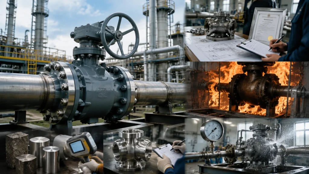
A quality manager at a valve distribution company once told me something that stuck: “We don’t sell valves. We sell the confidence that when you close the valve, the flow stops.” An industrial ball valve that doesn’t seal is not a valve. It’s a very expensive pipe fitting. The confidence that a ball valve will seal when you need it to comes from three things: the design standard it was built to, the testing it passed, and the certifications that verify both. Here’s what those standards and tests actually mean, and how to read a valve’s documentation to know whether you’re buying confidence or just buying metal. The standards that govern industrial ball valves API 6D is the Specification for Pipeline Valves. It covers design, manufacturing, materials, testing, and inspection for ball, gate, plug, and check valves in pipeline systems from NPS 2 to NPS 60, Class 150 to 2500. The 2015 edition – the 24th – made Double Block and Bleed mandatory and completely revised the pressure-temperature rating tables. The 2022 edition added quarterly partial stroke testing recommendations for emergency shutdown valves. If a valve is stamped API 6D, it was designed, manufactured, and tested to this standard. If the documentation can’t prove that, it wasn’t. API 6D certified industrial ball valves cover the full range of pipeline applications from Class 150 to Class 2500. API 608 covers metal ball valves for process piping. It applies to valves up to NPS 24 and Class 600. API 608 valves are typically used in process plants – refineries, chemical plants, power stations – rather than long-distance pipelines. The testing requirements are similar to API 6D but the design requirements are less stringent because process plant valves are generally in more accessible locations and operate at lower pressures than pipeline valves. Chevron’s 2019 onshore pipeline specification replaced API 608 with API 6D for all ball valves NPS 4 and above, which is part of a broader industry trend toward requiring API 6D for larger pipeline isolation valves. ASME B16.34 covers valve body wall thickness and pressure-temperature ratings. Every industrial ball valve body is designed to this standard or an equivalent. The standard provides the formulas and tables that determine the minimum wall thickness for each material group at each pressure class and temperature. A valve that meets API 6D or API 608 automatically meets B16.34 for the body design, because both API standards reference B16.34 for pressure-containing envelope requirements. Industrial ball valve specifications per API 6D include the B16.34 wall thickness calculation as a mandatory design verification. API 598 covers valve inspection and testing. This is the standard that defines the hydrostatic shell test, the seat closure test, and the acceptance criteria for both. Every industrial ball valve sold with an API certification has been tested per API 598. The shell test applies 1.5 times the rated pressure at 38C and holds it for a duration based on valve size – 15 seconds for valves up to DN50, 60 seconds for DN300 and above, and proportionally for sizes in between. The seat test applies 1.1 times the rated pressure. For soft-seated valves in gas service, the seat test uses gas at 0.4 to 0.7 MPa, and the acceptance criterion is zero visible bubbles. API 607 and API 6FA cover fire-safe testing. A fire-safe valve is placed in a furnace at a minimum of 760C for 30 minutes while pressurized, then quenched with water, then tested for external and seat leakage. After all that, the stem must be operable with a standard wrench. A valve that passes this test won’t add fuel to a fire. The fire-safe certification is not automatically included with API 6D or API 608. It’s a separate test, typically done once per valve design family, and the test report should match your valve’s size, class, and seat material. Fire-safe industrial ball valves certified to API 607 are standard for hydrocarbon service where fire exposure is a credible risk. NACE MR0175 and ISO 15156 cover materials for sour service – environments containing hydrogen sulfide. For carbon and low-alloy steels, the maximum hardness is HRC 22. This limit is not negotiable. Steel harder than HRC 22 exposed to wet H2S will crack through sulfide stress corrosion, and the cracking can happen in hours to weeks depending on the H2S concentration and the stress level. Every metallic component that contacts the process fluid in a sour service valve must meet the hardness limit, and the material certificate must state actual measured values, not just “NACE compliant.” What the testing actually verifies The hydrostatic shell test verifies that the pressure-containing envelope – the body, the body-to-bonnet or body-to-body joint, and the stem seal – can contain 1.5 times the rated pressure without leaking or deforming. The test uses water because water is nearly incompressible, so a failure releases a small amount of energy. Testing with gas is dangerous at high pressure because the stored energy in compressed gas can turn a body failure into an explosion. API 598 allows gas testing only when water cannot be used, and requires extensive safety precautions. The shell test finds gross defects. A body with a casting defect that penetrates the wall will leak. A body joint with a damaged gasket will leak. A stem seal that’s missing packing will leak. The test won’t find small defects that are below the surface, and it won’t find defects that are oriented such that they don’t create a leak path at the test pressure. The shell test is necessary but not sufficient for verifying casting integrity. Radiographic or ultrasonic inspection is required for that. The seat test verifies that the valve seals when closed. The test applies pressure to one side of the closed ball and measures leakage past the seat. For soft-seated valves in liquid service, the acceptance criterion is typically no visible leakage for the duration of the test. For metal-seated valves, the acceptance criterion is a specified leakage rate per API 598, typically rate B
How to Choose an Industrial Valve Manufacturer丨 What Separates a Supplier From a Partner

In 2017, a petrochemical plant in the Middle East ordered 300 valves for a new process unit. Gate, globe, check, and ball valves. Classes 150 through 900. Carbon steel and stainless. The procurement team sent the same RFQ to seven manufacturers, evaluated the quotes on price and lead time, and awarded to the lowest bidder. The valves arrived on schedule and passed visual receiving inspection. Six months into operation, the gate valves started sticking. The globe valves were leaking past the seats. The check valves were hammering on closure. None of them had failed catastrophically. They were just underperforming in ways that added up: higher maintenance costs, more frequent shutdowns, reduced throughput from valves that wouldn’t open fully. The root cause analysis found the same pattern across all three valve types: materials that met the minimum specification but had no margin, machining tolerances that were at the limit of what the drawings allowed, and testing that was done to the minimum API requirement with no additional verification. The valves were technically compliant. They were also functionally inadequate. The plant spent the next two years replacing them in batches, always during planned turnarounds because they couldn’t afford the downtime to do it all at once. Total cost of the cheap valves over five years: about 2.5 times what the best quote would have cost up front. Choosing an industrial valve manufacturer is fundamentally different from choosing a valve. A valve is a product. A manufacturer is a relationship that will determine whether your valves work, whether they keep working, and what happens when they stop. The difference between a supplier and a partner shows up in the first problem you have, not in the first purchase order you place. Here’s what separates the two. The difference between compliance and capability Every industrial valve manufacturer lists their certifications. ISO 9001. API 6D. API 600. API 602. CE marking. The certificates look the same regardless of who issues them. But certification tells you the manufacturer has a documented process. It doesn’t tell you whether the process produces good valves. An ISO 9001 certificate means the manufacturer has a quality management system with documented procedures for design, purchasing, production, inspection, and corrective action. The auditor verified that the procedures exist and are being followed at the time of the audit. But ISO 9001 audits are typically conducted once a year and sample a fraction of the production output. A manufacturer can pass an ISO audit with a 5% internal rejection rate, or they can pass with a 0.5% rejection rate. Both get the same certificate. The difference in quality between those two manufacturers is an order of magnitude, but the certificate doesn’t reveal it. The real questions to ask about compliance go beyond the certificate. Here is what you should ask: What’s your internal rejection rate over the last twelve months? What are the top three reasons for rejection? How do you track rejection trends and what corrective actions have you implemented in the last year? A manufacturer who can answer these questions with specific data – not general statements about “quality culture” – has a quality system that’s actually being used. A manufacturer who says they don’t track rejection rates, or that their rejection rate is zero, is either not measuring or not telling the truth. API 6D certification is the baseline for pipeline valves. But API 6D allows a range of testing rigor. The standard requires a hydrostatic shell test at 1.5 times rated pressure and a seat test at 1.1 times rated pressure. It doesn’t specify whether the seat test is done with water or gas. It doesn’t require helium leak detection. It doesn’t require anti-static testing beyond design verification. A manufacturer who does the minimum API 6D testing and a manufacturer who adds gas seat testing, helium leak detection, and anti-static verification on every valve are both API 6D certified. The test reports will look different, and the valves will perform differently in service, but that difference isn’t captured by the certification alone. API 6D certified valve manufacturers who invest in testing beyond the minimum are typically the ones whose valves don’t come back on warranty claims. Manufacturing depth: what they make vs what they buy Industrial valve manufacturing is a supply chain game. The foundry pours the castings. The forge shop produces the forgings. The machine shop turns the raw castings and forgings into finished components. The assembly shop puts everything together and tests it. Most manufacturers operate the assembly and testing in-house and outsource the casting and forging to specialist suppliers. The quality of the finished valve depends as much on the casting and forging suppliers as on the final assembly. A manufacturer with in-house foundry and forge capabilities controls the entire process from raw material to finished valve. They can verify the heat chemistry at the furnace, control the pouring temperature and cooling rate, and inspect the casting before it ever leaves their facility. They can trace every component back to a specific heat of steel, poured on a specific day, by a specific operator. The documentation chain is unbroken because nothing leaves their control. A manufacturer who outsources casting and forging has to rely on their suppliers’ quality control. They receive the castings, do incoming inspection, and hope they didn’t miss anything. The inspection catches surface defects and dimensional errors. It doesn’t catch internal porosity unless they’re doing radiographic or ultrasonic inspection on every casting. Most manufacturers sample-inspect incoming castings. A 10% sampling rate will catch systemic problems. It won’t catch the one casting in ten that has an inclusion just below the surface at a critical stress concentration point. This isn’t to say that outsourced manufacturing is inherently worse. Some of the best valve manufacturers in the world outsource their castings to specialist foundries that produce better castings than any valve manufacturer could make in-house. The key is whether the manufacturer audits their suppliers, verifies incoming material with PMI and dimensional inspection, and can
How to Size a Ball Valve for Steam Service | Temperature Derating and Material Limitations
Valve sizing for steam systems differs fundamentally from liquid service. Temperature is a primary factor that determines body pressure-temperature rating, seat material, bolting grade, stem packing, and bonnet design. Steam valve selection is not only a pressure-class decision. It requires a combined check of steam state, operating temperature, design pressure, body material derating, seat material, stem packing, bolting, and leakage acceptance requirements. For steam service, always size the valve at the actual design temperature, not at the room-temperature pressure rating. Selection Checkpoint What to Confirm Why It Matters Steam state Saturated, wet, dry saturated, or superheated steam Determines the actual media temperature and the suitability of soft seats or metal seats. Temperature Operating temperature and design temperature Controls PTFE/RPTFE limits, packing life, bolting relaxation risk, and body material derating. Pressure-temperature rating ASME B16.34 rating at service temperature Prevents using room-temperature pressure ratings in high-temperature steam service. Seat material PTFE, reinforced PTFE, carbon-filled PTFE, PEEK, or metal seat Determines sealing reliability under heat, pressure, cycling, and particle contamination. Bolting and packing ASTM A193 B7/B16, ASTM A453 Gr.660, PTFE packing, or graphite packing Maintains bonnet joint preload and stem sealing reliability under thermal load. Leakage acceptance ISO 5208, API 598, API 6D, or project-specific leakage class Defines measurable leakage limits instead of relying on vague “zero leakage” claims. Steam Parameters Saturated vs. Superheated Steam Understanding the steam state is the first step in valve selection. Saturated steam is steam at the saturation temperature corresponding to a given pressure. It may be dry saturated steam or wet steam containing entrained liquid droplets. Saturated steam temperature has a direct relationship with pressure. For engineering selection, gauge pressure should be converted to absolute pressure before reading the steam table. Based on standard steam table values, 1.0 MPa(g) corresponds to about 184°C, 2.0 MPa(g) to about 214°C, and 3.0 MPa(g) to about 235°C.[1] Gauge Pressure Approximate Saturation Temperature Valve Selection Impact 1.0 MPa(g) About 184°C Close to the practical upper range of standard PTFE in demanding steam service. 2.0 MPa(g) About 214°C Soft-seat margin becomes narrow, especially with frequent thermal cycling. 3.0 MPa(g) About 235°C Reinforced PTFE or carbon-filled PTFE may require manufacturer confirmation. 3.0 MPa(g), superheated to 300°C About 65°C above saturation Metal seats and graphite packing should normally be evaluated as the baseline configuration. Superheated steam is steam heated above the saturation temperature at the same pressure. For example, 3.0 MPa(g) steam superheated to 300°C is approximately 65°C above its saturation temperature.[2] The effect on valve selection is significant. Medium-pressure saturated steam may already be close to the practical limit of PTFE seats. Superheated steam can exceed 250°C and increase the risk of polymer creep, compression set, sealing-surface damage, and leakage growth. If saturated steam is mistakenly treated as superheated steam, the valve may be over-specified and cost may increase unnecessarily. The reverse error is more serious. Treating superheated steam as saturated steam can cause soft seats and PTFE packing to lose sealing performance earlier than expected. When steam conditions are ambiguous, confirm the steam state from the process datasheet before selecting the seat material. Temperature margin above saturation is a key parameter. If the superheat margin is large, soft-seat reliability becomes less predictable, even when the nominal pressure class appears acceptable. For steam lines above about 250°C, CARILO forged metal-seated ball valves can be considered where reliable sealing and longer maintenance intervals are required. Further reading: CARILO forged metal-seated ball valves API 6D ball valve range Contact CARILO for steam service selection support Pressure-Temperature Rating Tables Engineers should not rely on pressure-class estimation alone. ASME B16.34 covers pressure-temperature ratings, dimensions, tolerances, materials, nondestructive examination requirements, testing, and marking for flanged, threaded, welding-end, wafer, and flangeless valves.[3] The ASME B16.34 tables are organized by valve material, pressure class, and temperature. The rows list temperature points, while the columns list pressure classes such as Class 150, 300, 600, 900, 1500, 2500, and 4500. Each intersection gives the allowable working pressure at that temperature. The allowable pressure generally decreases as temperature increases. Example Material Pressure Class Temperature Approximate MWP Selection Meaning ASTM A216 WCB Class 600 -29°C to 38°C 10.20 MPa Ambient-range pressure rating only. ASTM A216 WCB Class 600 250°C 8.39 MPa Derating is already significant. ASTM A216 WCB Class 600 350°C About 7.5 MPa Do not use the ambient rating for sizing. ASTM A216 WCB Class 600 425°C 5.75 MPa High-temperature pressure margin becomes much narrower. For example, a Class 600 valve with ASTM A216 WCB body material has a maximum working pressure of about 10.20 MPa in the -29°C to 38°C range. It drops to about 8.39 MPa at 250°C, about 7.5 MPa at 350°C, and about 5.75 MPa at 425°C, based on publicly available ASME B16.34 pressure-temperature data.[4] Sizing a steam valve only by its room-temperature class rating can lead to under-rating at high temperature. This may increase the risk of pressure-boundary overstress, bonnet joint leakage, gasket failure, or premature sealing problems. Pressure-temperature verification should not stop at the valve body. The bonnet, pressure-containing joint, bolting, gasket, and end connections must also satisfy the design temperature and pressure requirements. Take the design pressure and design temperature from the process datasheet. Identify the valve body material and applicable pressure class. Read the ASME B16.34 allowable pressure at the design temperature. Confirm that the derated allowable pressure is higher than the design pressure. Apply the same check to the bonnet, bolting, gasket, flange, and pressure-containing joints. For a valve installed as part of a pipeline assembly, the governing allowable pressure is the lowest-rated component after temperature derating. In high-temperature steam systems, this can be the valve, its bolting, its gasket system, or the adjoining flange rating. Further reading: CARILO ball valve product range PTFE Seat Temperature Limits PTFE, or polytetrafluoroethylene, is one of the most common seat materials for soft-seated ball valves. PTFE has a high melting point, and engineering data often allows PTFE components to be used continuously up to about 260°C under suitable conditions.[5] However, steam valve seats should not be
How to Troubleshoot a Leaking Ball Valve in the Field | Stem Leak vs Seat Leak Diagnosis
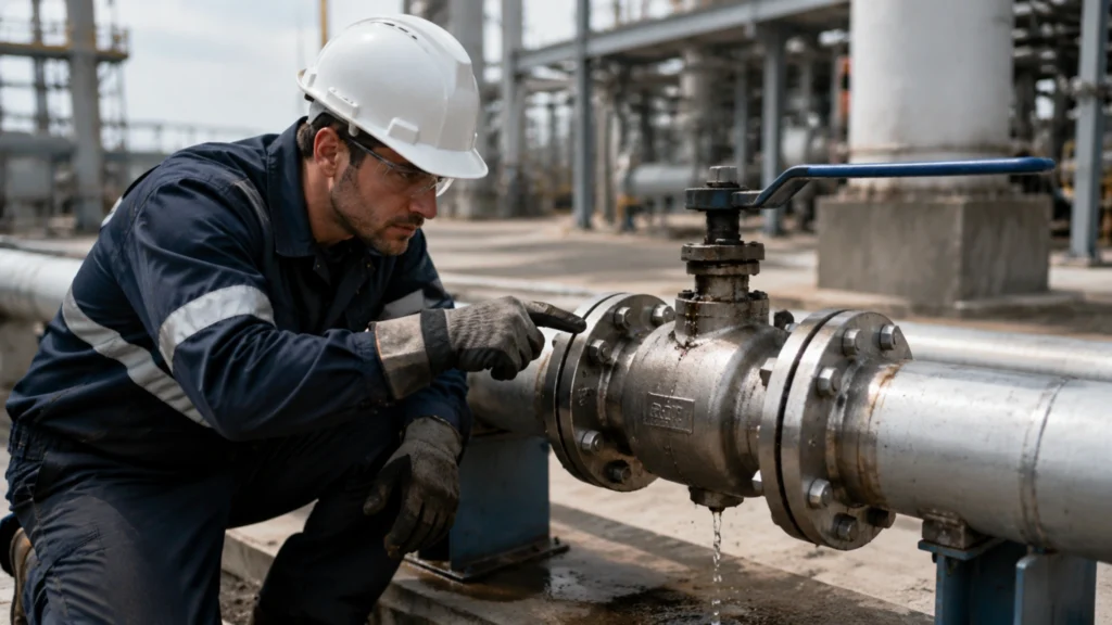
Ball valves are widely used shut-off devices in oil and gas, petrochemical, chemical processing, water treatment, and industrial pipeline systems. When leakage appears in the field, the first step is not to replace parts immediately. The first step is to identify the actual leak path. Most ball valve leakage problems can be separated into two broad categories: external leakage and internal seat leakage. External leakage includes stem packing leakage and flange joint leakage. Internal leakage usually means the valve fails to hold pressure when fully closed. API 6D ball valves should be diagnosed in a clear field sequence: identify the leak path first, then select the corrective action. API 6D defines requirements for the design, manufacturing, assembly, testing, and documentation of ball, check, gate, and plug valves for pipeline and piping systems in the petroleum and natural gas industries.[1] Many valve leakage problems in service are linked to installation conditions, thermal cycling, process contamination, incorrect operation, actuator adjustment, or maintenance practices. The valve body itself should not be blamed until the leak point is confirmed. Minor checks such as visual inspection, packing observation, flange joint inspection, and downstream leakage confirmation can often be performed with basic field tools. Repairs involving pressure-containing parts, seat refacing, oxygen service, hydrogen service, sour gas, toxic media, or flammable media must follow the valve manufacturer’s manual and the site’s approved safety procedure. Leak Scenario Typical Leak Location Key Field Sign First Corrective Action Stem leak Around the stem and packing chamber Leak remains at the stem area even when the valve is closed Check packing gland preload, packing condition, stem surface, and secondary seal condition Pipeline flange joint leak Valve end flange or mating pipeline flange External leak appears at the flange gap and is usually less dependent on ball position Check gasket condition, flange alignment, bolt load, and tightening sequence Valve not holding when closed Ball-to-seat sealing interface Downstream leakage appears after full closure Check seat damage, particle jamming, actuator stop setting, seal wear, or thermal distortion Locating the Leak Source Stem Leak A stem leak occurs when process medium escapes through the sealing area around the valve stem and packing chamber. For a quarter-turn ball valve, the stem rotates during operation. The packing must seal the stem while still allowing controlled movement. Industrial valve troubleshooting guidance commonly separates valve leakage into seat leakage and shell leakage. Seat leakage means fluid passes through the internal closure mechanism. Shell leakage means fluid leaks outside the valve body into the atmosphere, often through the stem or body area.[2] Leakage is concentrated around the stem penetration, packing gland, or bonnet area. Medium visibly drips, seeps, bubbles, or leaves residue around the stem. The leak remains at the stem area after the valve is fully closed. The last point is the key difference from seat leakage. If the valve is fully closed but leakage continues from the stem area, the leak path is external and related to the stem sealing system. Typical root causes include insufficient packing gland preload, aged packing rings, thermal cycling, packing extrusion, stem scratches, corrosion on the stem surface, chemical attack, or a damaged O-ring or secondary seal. In one DN50 Class 150 floating ball valve field case, the valve had been dripping from the stem for a long period before maintenance support was requested. After disassembly, the PTFE packing rings had hardened and shrunk, leaving a small gap in the stuffing box. After the full packing set was replaced and the gland was tightened according to the manufacturer’s maintenance sheet, no visible leakage was observed during the field check. If the leak is caught early, small and even packing adjustment may stop minor seepage without full disassembly. Do not tighten the packing gland aggressively. Excessive gland load can increase operating torque, damage the packing, score the stem, or make the valve difficult to operate. Pipeline Flange Joint Leak A pipeline flange joint leak occurs when process medium escapes from the sealing interface between the valve end flange and the mating pipeline flange. It usually appears at either the upstream or downstream flange connection. This should not be confused with a valve body joint leak. In many valve documents, “body flange” may refer to a valve body-cover joint rather than the pipe-end flange connection. For this reason, “pipeline flange joint leak” or “valve end-flange joint leak” is more accurate when the leakage is at the pipe connection. In most cases, a flange joint leak is less dependent on ball position than seat leakage because the leak path is outside the ball-to-seat sealing interface. However, the leak rate can still change if the downstream side is depressurized or if pressure distribution changes after the valve is closed. ASME PCC-1 provides guidelines for pressure-boundary bolted flange joint assembly. It applies to pressure-boundary flanged joints with ring-type gaskets and is commonly used to develop effective flange assembly procedures for industrial pressure systems.[3] Scratched, corroded, or contaminated flange faces can prevent proper gasket seating. Wrong gasket type, wrong gasket size, or excessive compression can cause early gasket failure. Uneven bolt preload can come from poor alignment, non-cross-pattern tightening, unlubricated bolts, or uncalibrated torque tools. Thermal cycling and gasket relaxation can reduce bolt load after installation. Garlock’s metallic gasket installation guidance emphasizes correct bolting pattern, calibrated torque tools, and applicable safety procedures. It also warns against retightening a flange connection once it has been brought up to temperature or pressure.[4] In one DN80 PN40 chemical plant case, leakage appeared at the lower flange gap after several thermal cycles during unit startup. The gasket had likely experienced stress relaxation and reduced sealing stress. The flange bolts were retightened only after the section was made safe, using a calibrated torque wrench, the site-approved torque table, and a cross-pattern sequence. The leak stopped without replacing the gasket. The torque value used in that case should be treated only as a site-specific maintenance value, not as a universal torque recommendation. Pipeline flange joint leaks are sometimes misidentified as valve body casting cracks.
How to Understand API 6D vs API 6A Ball Valves | Pipeline vs Wellhead Application Differences
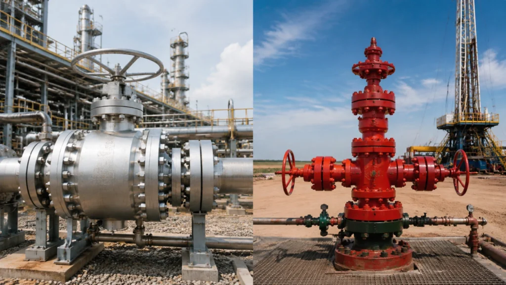
API 6D and API 6A are two valve-related standards that are often confused in oil and gas procurement. API 6D is commonly used for pipeline and piping valves, while API 6A governs wellhead and Christmas tree equipment. Their pressure systems, end connections, testing basis, and certification scopes are very different. For example, a carbon steel API 6D Class 600 valve may have a hydrostatic shell test pressure around 15 MPa when calculated from its ASME pressure-temperature rating at ambient temperature. By contrast, an API 6A 15K wellhead valve may require a body test pressure around 155 MPa, depending on the applicable API 6A test table and product configuration[1][2][3]. In import and export valve projects with EPC contractors, the wrong standard can lead to failed technical review, connection mismatch, or rejection during inspection. This makes it important to confirm the governing standard before procurement. Pipeline ball valves generally follow API 6D. Wellhead valves generally follow API 6A. The two standards are not interchangeable by name, size, pressure rating, or certificate alone. Comparison Item API 6D Ball Valve API 6A Valve Main application Oil and gas pipelines, transmission lines, refineries, and process piping systems Wellhead, Christmas tree, and upstream production equipment Pressure system Usually ASME Class system, such as Class 150 to Class 2500 Rated working pressure system, such as 2K, 3K, 5K, 10K, 15K, and 20K psi Typical end connections RF flange, RTJ flange, BW butt weld, and project-specified pipeline ends API 6A flanges, threaded ends, hubs, and RTJ sealing faces Core selection concern Pigging, pipeline isolation, pressure class, end connection, and flow bore Sour service, sand erosion, high pressure, PSL, PR level, and wellhead compatibility Interchangeability Not interchangeable with API 6A equipment without engineering review Not interchangeable with API 6D pipeline valves without engineering review Two Standards Where API 6D Is Used API 6D is currently published by API as “Specification for Valves.” It defines manufacturing requirements for valves and is widely used for pipeline and piping valve applications in the oil and gas industry[4]. It is commonly applied to ball valves, gate valves, plug valves, check valves, and axial valves used in pipeline systems. The core application scenario is pipeline isolation and pressure containment between pipeline sections. Typical operating modes include normally open service, periodic operation, block isolation, and emergency isolation. API 6D valves may be specified as full-opening or reduced-opening designs. Full-opening ball valves are commonly selected when pig passage is required. I participated in valve selection for a Central Asia natural gas pipeline project where the EPC required block valves to comply with API 6D. The reason was simple: the pipeline had a strict pigging requirement, and API 6A does not define pipeline pigging requirements. For pipeline ball valve selection, refer to API 6D ball valve specifications, which include pressure class and end connection tables for common pipeline applications. API 6D valves are commonly specified under ASME Class ratings, such as Class 150, 300, 600, 900, 1500, and 2500. The actual allowable pressure depends on material group and service temperature according to the applicable pressure-temperature rating system[5]. Class 600 and Class 900 are common pressure classes for long-distance oil and gas pipeline ball valves. RF flanges, RTJ flanges, and BW butt weld ends are common connection types. BW ends are often preferred for high-pressure long-distance pipelines because they reduce flange leakage points. Many conventional pipeline projects specify service temperatures around -29°C to 121°C, but this is not a fixed API 6D temperature range. The final temperature limit must be checked against body material, seat material, pressure-temperature rating, and project specifications. Further reading: Carilo API 6D High Pressure Ball Valve Product Page, API 6D Trunnion Mounted Ball Valve Specifications and Test Standards. Where API 6A Is Used API 6A is published as “Specification for Wellhead and Tree Equipment.” It applies to equipment used at oil and gas wells, including wellhead equipment, Christmas tree equipment, valves, and related pressure-containing components[6]. This standard is mainly used in upstream exploration and production. In these applications, the service media may come directly from the wellbore and may contain H₂S, CO₂, water, chlorides, sand, and other corrosive or erosive components. H₂S service requires attention to sulfide stress cracking and other H₂S-related cracking mechanisms. NACE MR0175 / ISO 15156 is commonly used for metallic material selection in H₂S-containing oil and gas production environments[7]. Material suitability depends on service conditions such as H₂S partial pressure, CO₂, chloride content, pH, temperature, hardness, and material strength. For H₂S service, duplex stainless steel and cast ball valves can be considered when they are properly selected and qualified under the applicable sour service requirements. Duplex materials may provide high strength and corrosion resistance, but they must still be checked against the exact NACE MR0175 / ISO 15156 limits for the project. API 6A pressure ratings are specified as rated working pressure values. Common ratings include 2K, 3K, 5K, 10K, 15K, and 20K psi, which correspond approximately to 13.8 MPa to 138 MPa. This is different from the ASME Class system commonly used for API 6D pipeline valves. API 6A also uses temperature classes, material classes, product specification levels, and performance requirement levels. The allowable temperature range must therefore be confirmed from the selected API 6A edition, temperature class, seal design, material, and PR requirement. Based on Middle East oilfield project experience, API 6A valve sealing surfaces may require corrosion-resistant or hardfacing overlays such as Inconel 625 or Stellite 6, depending on service conditions. This is different from many API 6D pipeline ball valves where soft seats are often used for tight shutoff in clean pipeline service. The reason is the difference in service severity. Wellhead media can be corrosive, high-pressure, multiphase, and erosive. If a conventional API 6D soft-seated ball valve is used in a severe wellhead environment without proper engineering review, accelerated seat damage, torque increase, or leakage may occur. This difference in service condition is one reason why API 6D and API 6A follow separate design, testing, and certification paths. Further reading: Carilo Forged Metal Seated
How to Protect Ball Valves from Sand and Abrasive Media in Oil Production | Hard Coating Solutions
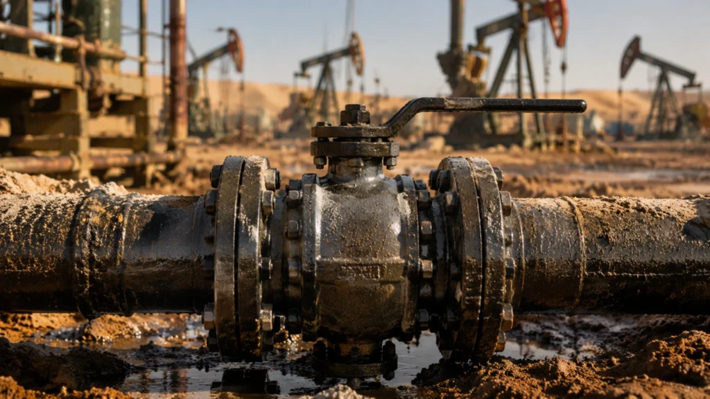
In oil production with sand-laden fluids, seal-face wear on ball valves is a common cause of internal leakage, torque increase, and unplanned valve replacement. Practical protection normally combines sand-severity screening, velocity control, wear-resistant sealing surfaces, debris-control seat geometry, and inspection intervals based on measured wear history. In one Middle East oilfield project, produced fluid entering the valve package intermittently contained 0.8%–1.2% sand by volume during sand-upset periods before final sand-control improvement. The uncoated stainless-steel seat set was replaced 3 times in 12 months, and each replacement cost around USD 28,000 including parts, field labor, and pressure testing. The field values in this article are project screening values from reviewed sand-laden service cases. They are not universal design limits from API 6D, ISO 17292, API 598, or any other valve product or test standard. For formal oil and gas sand-management and erosion-assessment work, DNV-RP-O501 provides a dedicated recommended-practice framework for managing sand production and erosion through design and operation of production facilities.[1] Erosion Mechanisms How Much Sand Is Considered Severe Solid particles in produced fluids can damage the ball, seat, coating layer, and nearby flow passages. The damage rate depends on particle hardness, particle size, particle shape, concentration, velocity, impact angle, fluid phase, pressure drop, valve geometry, and cycling frequency. API Specification 6D is a valve specification used internationally to define manufacturing requirements for valves. It should not be interpreted as a sand-content limit or maintenance-interval standard for metal-seated ball valves in dirty production service.[2] Sand Content by Volume Observed Valve Performance in Reviewed Cases Practical Response 0.3%–0.5% Metal-seated valves with suitable seat material or coating commonly reached approximately 18–24 months when velocity and cycling were controlled. Review velocity, particle size, cycling frequency, seat material, coating requirements, and pressure drop across the valve. 0.5%–0.8% Wear risk increased clearly, especially where pressure drop or local jetting occurred near the seat. Use hard-coated or hardfaced seat-and-ball pairs and verify operating velocity. 0.8%–1.0% Uncoated stainless-steel seats in the reviewed cases often fell to 3–5 months. Upgraded metal-seated configurations with carbide coating or cobalt-based hardfacing sometimes reached 6–8 months before repair. Use a more aggressive erosion-control strategy from the start, including upstream sand removal and early inspection. Above 1.0% Service conditions were extremely severe and highly sensitive to flow velocity, particle size, pressure drop, and valve cycling. Use high-performance wear-resistant coatings, carbide-alloy seat pairs, upstream sand-removal equipment, and condition-based inspection. ISO 17292 specifies requirements for metal ball valves used in petroleum, petrochemical, natural gas plants, and related industrial applications. It should not be read as a service-life ranking standard for sand-laden production fluids.[3] A practical field method for assessing sand severity is to inspect groove depth on the seat seal face during teardown. The following limits were used as project inspection criteria, not as universal acceptance limits. Observed Groove Depth on Seat Seal Face Condition in Reviewed Failed-Seat Batches 0.1–0.3 mm The seal faces were usually repairable by controlled lapping, polishing, or re-coating, depending on remaining coating thickness and substrate condition. Above 0.3 mm The valves commonly showed through-seat internal leakage or could no longer meet the specified closure-test acceptance criterion. How Much Flow Velocity Affects Erosion Flow velocity is one of the most important variables in solid-particle erosion. Solid-particle erosion often increases nonlinearly with particle impact velocity. ASTM G76 is a laboratory method for measuring material loss from gas-entrained solid-particle impingement. It is useful for ranking erosion resistance under specified test conditions, but it also states that actual service may vary widely in particle size, velocity, attack angle, environment, and other factors; therefore, one laboratory test alone is not enough to predict field performance.[4] The API RP 14E erosional-velocity equation is a screening tool for production piping, not a valve-specific seal-face wear equation. Published reviews have noted that API RP 14E does not adequately account for several factors that strongly affect erosion, including material properties, flow geometry, flow regime, sand production rate, and corrosive species.[5] Field Parameter Lower-Velocity Condition Higher-Velocity Condition Sand content 0.6% 0.6% Flow velocity 3 m/s 6 m/s Monthly seal-face wear 0.02 mm 0.09 mm Measured increase Baseline 4.5× The wear data above came from a reviewed field comparison under the same sand-content category. It should not be converted into a universal erosion formula because valve size, trim geometry, pressure drop, particle distribution, and fluid phase can change the result significantly. For the reviewed sand-laden projects, the following working velocity limits were used as engineering controls. They should be adjusted after checking particle size distribution, pressure drop, valve size, valve bore geometry, and fluid phase. Sand Content by Volume Project Working Velocity Limit 0.3%–0.5% 4.5 m/s 0.5%–1.0% 3.0 m/s In one Canadian oil sands project, a Class 600 ball valve developed severe internal leakage after only 4 months when velocity was not controlled. After the valves were upgraded with tungsten-carbide-coated seats and operating velocity was reduced from 5.5 m/s to 3.2 m/s, metal-seated valve life increased to more than 14 months in the same service envelope. Valve groups cycled 5 times/day were used as the lower-frequency comparison. Valve groups cycled 20 times/day showed approximately 60% faster seal-face wear. Unnecessary open-close cycles should be minimized in sand-laden pipelines. The Seat Fails First In sand-laden service, the seat seal face is often the first ball-valve component to lose sealing function. Inspection Finding Observed Result Failed valves inspected More than 40 Failures attributed mainly to seat seal-face erosion More than 85% Other common damage Ball-surface scoring and stem-packing wear Uncoated stainless-steel seats at about 0.8% sand 3–5 months of measured service life WC-sprayed or Stellite-hardfaced seats under comparable reviewed conditions 12–24 months of measured service life Seat failure is promoted by concentrated sealing pressure. When the valve closes, hard particles can become trapped between the ball and the seat and act as a grinding layer. In one water-injection project using sand-laden produced fluid, visible grooves appeared on the pressure-side seat face within 2 months while the stem and packing box on the same valve remained serviceable. If sand content is expected to exceed
How to Calculate Pressure Drop Across a Ball Valve | Cv Values and Flow Coefficient Guide
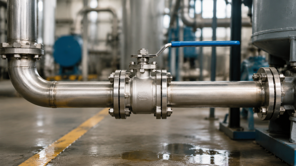
In industrial piping systems, calculating ball valve pressure drop directly affects pump or compressor duty, available downstream pressure, operating cost, and system reliability. The Cv value quantifies a valve’s flow capacity. In US customary practice, Cv is commonly expressed as the flow rate of 60°F water, in US gallons per minute, that produces a pressure drop of 1 psi across the valve under stated test conditions.[1] Cv should not be treated as interchangeable between different valve models, port designs, seat constructions, opening positions, or manufacturers. For a ball valve, the selected Cv should be checked against the exact manufacturer’s data for the selected valve configuration, including whether the valve is full-port, reduced-port, or partially open. Calculation Item Main Input Data Main Engineering Check Liquid pressure drop Flow rate, liquid specific gravity, and valve Cv Confirm turbulent flow, viscosity correction, vapor pressure, and allowable pressure-drop budget Gas pressure drop Standard gas flow, absolute inlet pressure, temperature, gas specific gravity, compressibility, Cv, and xT Determine whether the actual pressure-drop ratio reaches the valve-specific choked-flow limit Full-port or reduced-port selection Valve bore, manufacturer Cv data, pipeline velocity, and pigging requirements Compare pressure drop, installation cost, and operating requirements Cavitation and flashing Upstream pressure, downstream pressure, vapor pressure, FL, and fluid temperature Distinguish between vapor collapse and continuous two-phase flow Cv Value Fundamentals What Does Cv Mean? Cv stands for valve flow coefficient. It is widely used in valve sizing to compare flow capacity and estimate pressure drop across valves and other flow restrictions. Cv represents US gallons per minute of 60°F water at a 1 psi differential pressure. A higher Cv means greater flow capacity under the same operating conditions. For the same liquid and flow rate, a higher Cv produces a lower calculated pressure drop. A listed rated Cv normally refers to the valve at its specified full-open or rated-travel position. A higher Cv does not automatically mean that a valve is suitable for the application. Pressure rating, bore, seat material, shutoff performance, velocity, noise, cavitation, flashing, operating torque, and maintenance requirements must also be checked. In one refinery medium-pressure steam procurement, the buyer required Cv ≥ 400 for an API 6D forged ball valve, but the supplied valve was reported at Cv = 320. After the supplier data were rechecked, the valve was replaced with a larger-capacity model. The case illustrates why Cv should be confirmed from the selected manufacturer’s capacity data rather than assumed from nominal pipe size alone. Cv is not a universal constant for every valve of the same nominal size. It is affected by: Ball opening angle or valve travel Full-port or reduced-port geometry Seat and bore design Internal flow-path shape Surface roughness Attached reducers and fittings Flow direction in an asymmetrical design Some suppliers provide Cv curves at different valve positions, such as 30°, 60°, and 90° of ball rotation. These curves are especially important when a ball valve is used for a partially open operating condition instead of simple on-off isolation. API 6D covers pipeline and piping valves such as ball, gate, plug, and check valves. It is a product standard for valve design, manufacturing, assembly, testing, marking, and documentation; it should not be read as a source of universal Cv values. Rated Cv and partial-opening curves should be obtained from the manufacturer’s technical data for the exact valve model.[2] The 1 psi differential in the Cv definition is a reference condition. A manufacturer may conduct a capacity test at another suitable differential pressure and calculate the equivalent flow coefficient according to the applicable test method. IEC 60534-2-3 and ISA-75.02.01 describe capacity test procedures for variables such as flow coefficient C, FL, FP, xT, xTP, Fd, and FR.[3] For viscous liquids, correction should be based on valve Reynolds number and the Reynolds-number factor described in IEC 60534-2-1 or the corresponding ISA sizing method.[4] ISO/TR 15377:2023 covers differential-pressure flow-measurement devices such as orifice plates, nozzles, and Venturi tubes beyond the scope of the ISO 5167 series. It is not the correct primary standard for ball-valve Cv viscosity correction.[5] In one valve-selection review, the measured flow result differed from the published Cv table by about 18%. Testing water at 10°C instead of 60°F, approximately 15.6°C, cannot by itself explain an 18% Cv difference. Published water-density data show that water density changes only slightly between 10°C and 60°F, so a deviation of that size is more likely to involve valve travel, pressure-tap location, piping geometry, flow conditioning, test accuracy, or incorrect reporting.[6] When verifying Cv, request a capacity test report prepared according to ISA-75.02.01 or IEC 60534-2-3. ISA-75.01.01 and IEC 60534-2-1 are primarily sizing-equation standards, while ISA-75.02.01 and IEC 60534-2-3 address capacity test procedures.[7] Further reading: CARILO Forged Soft-Seated Ball Valve Cv Parameters、Valve Material Selection & Corrosion Guide. Full Port vs Reduced Port Cv Feature Full-Port Ball Valve Reduced-Port Ball Valve Internal opening Designed to provide a larger internal passage, typically close to the connected pipe bore when full-opening requirements apply Uses a smaller internal passage than a full-port valve of the same nominal pipe size Typical Cv Normally higher, but the exact value is manufacturer-specific Normally lower because of the restricted passage and pressure recovery Pressure drop Lower at the same flow rate Higher at the same flow rate Pigging Normally selected when unrestricted conventional pig passage is required Normally unsuitable for conventional full-bore pigging unless the system uses a specially designed pigging arrangement Cost and weight Often higher May be lower, depending on design and pressure class A full-port ball valve does not have a Cv equal to a fixed percentage of an open pipe because an open pipe does not have a single universal Cv value. Pipe length, roughness, fittings, Reynolds number, and pressure-tap basis all affect the equivalent resistance comparison. The actual comparison must use tested or calculated manufacturer data for the specific valve size, bore, pressure class, seat design, and end connection. For an illustrative 4″ Class 600 floating ball valve, a full-port Cv of approximately 560 and a reduced-port Cv of
How to Handle Fugitive Emission Testing for Valves | ISO 15848-1 Class A/AH Certification Process
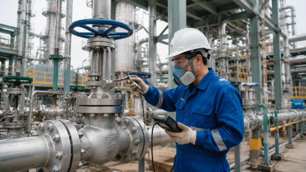
Fugitive emission (FE) testing for industrial valves verifies the external sealing performance of stem or shaft seals and body joints under controlled pressure, temperature, and cycling conditions. It is especially important for valves used with volatile air pollutants, hazardous fluids, methane-containing service, refinery units, LNG facilities, petrochemical plants, and projects where the purchaser requires low-emission valve qualification. ISO 15848-1:2015 is the international standard for classification and qualification procedures for type testing of industrial valves for fugitive emissions1. It applies to external leakage from valve stem or shaft seals and body joints of isolating valves and control valves. For helium testing, the strictest stem or shaft tightness class is AH. The AH limit is not a fixed total value for every valve; it is expressed per millimetre of stem diameter. ISO 15848-1:2015 states the AH leak-rate limit as ≤1.78×10⁻⁷ mbar·L/s per mm stem diameter2. For ISO 15848-1, a complete valve performance designation combines tightness class, test fluid, endurance class, temperature class, and stem seal adjustment history. A simple commercial phrase such as “Class A” is not enough for technical specification. Item Correct ISO 15848-1 / ISO 15848-2 Point Practical Meaning Tightness class Helium classes are AH, BH, and CH. Methane classes are AM, BM, and CM. AH is the strictest helium stem or shaft seal class. Endurance class For isolating valves, CO1 = 205 cycles, CO2 = 1,500 cycles, and CO3 = 2,500 cycles. For control valves, CC1 = 20,000 cycles, CC2 = 60,000 cycles, and CC3 = 100,000 cycles. The cycle count depends on valve type and selected endurance class. Temperature class Common classes include t-196°C, t-46°C, t-29°C, tRT, t200°C, and t400°C. The temperature class should match the required service range. Production acceptance ISO 15848-2:2015 is the production acceptance test for valves whose design has already been type-tested3. It is not a shortcut for replacing ISO 15848-1 type testing. Emission Standards ISO 15848 Classification ISO 15848-1 is formally titled “Industrial valves — Measurement, test and qualification procedures for fugitive emissions — Part 1: Classification system and qualification procedures for type testing of valves.” It specifies test procedures for evaluating external leakage from valve stem or shaft seals and body joints of isolating and control valves intended for volatile air pollutants and hazardous fluids. End connection joints, vacuum service, corrosion effects, and radiation effects are outside its scope4. The ISO 15848-1 performance code should be read as a qualification result, not as a single letter. A typical designation includes the standard, test medium, tightness class, endurance class, temperature class, and the number of permitted or performed stem seal adjustments, where applicable. Two valves can both be described commercially as “Class A” while having different cycle endurance or temperature qualification ranges. AH, BH, and CH apply when helium is used as the test fluid. AM, BM, and CM apply when methane is used as the test fluid. ISO 15848-1 states that no direct correlation is intended between helium classes and methane classes. Purchasers should specify the full ISO 15848-1 designation rather than only writing “Class A.” The EU Industrial Emissions Directive defines fugitive emissions as volatile organic compounds not contained in waste gases and released to air, soil, or water5. In refinery, LNG, petrochemical, and chemical projects, this regulatory pressure often appears in valve procurement specifications as ISO 15848-1 certificates, API fugitive-emission test reports, or project-specific LDAR acceptance criteria. For packing seal systems, expanded graphite reinforced with metallic wire is widely used in high-temperature and low-emission valve designs. Its suitability still depends on the complete packing set, gland load control, stem finish, surface hardness, packing chamber geometry, pressure, temperature, and cycling envelope. A packing material choice alone does not guarantee Class AH performance. In one internal batch review of 500 low-emission valves with reinforced expanded graphite packing, the first-pass FE test rate was 96%. That result should be treated as project-specific evidence, not as a universal yield rate for every valve type, size range, pressure class, temperature class, or supplier. The combination of packing type, packing compression, stem surface finish, gland load retention, body joint design, and assembly control determines whether a valve design can consistently achieve the selected ISO 15848-1 tightness class across production batches. Class AH vs BH vs CH and AM vs BM vs CM In ISO 15848-1, helium classes are AH, BH, and CH. Methane classes are AM, BM, and CM. Commercial documents often shorten these to Class A, Class B, and Class C, but the test fluid should always be stated because helium leak-rate classes and methane concentration classes are not interchangeable. Class Context A / AH / AM B / BH / BM C / CH / CM ISO 15848-1 helium stem or shaft seal AH ≤1.78×10⁻⁷ mbar·L/s per mm stem diameter BH ≤1.78×10⁻⁶ mbar·L/s per mm stem diameter CH ≤1.78×10⁻⁴ mbar·L/s per mm stem diameter ISO 15848-1 methane stem or shaft seal AM ≤50 ppmv BM ≤100 ppmv CM ≤500 ppmv Body joint leakage under ISO 15848-1 Body seal leakage is checked separately and is commonly limited to ≤50 ppmv by the sniffing method for the relevant test fluid. ISO 15848-2 production acceptance stem or shaft seal A ≤50 ppmv B ≤100 ppmv C ≤200 ppmv Typical use Highest emission-control requirement Balanced low-emission requirement General low-emission production control The standard does not define Class A, B, or C by allowing the final leakage rate to become three or five times higher than the initial value. Each required leakage measurement must remain within the selected tightness class limit. For helium Class AH, the allowable total stem or shaft leakage is calculated from stem diameter. For example, a measured total helium leak rate of 2.3×10⁻⁶ mbar·L/s would require a stem or shaft diameter of at least about 13 mm to remain within the AH limit. For a large refinery or LNG project, specifying Class A/AH valves can increase procurement cost compared with less stringent classes. The decision should be made from process risk, fluid hazard, LDAR burden, operating temperature, maintenance accessibility, owner environmental targets, and lifecycle
How to Prepare a Valve Data Book for Project Handover | MDR, Test Records, and Certification Compilation
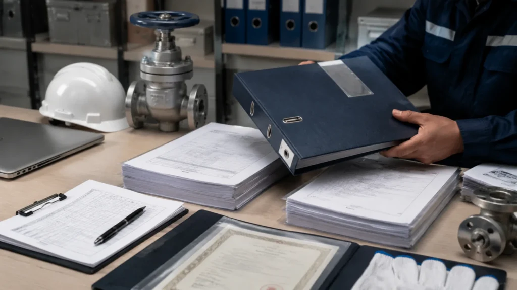
A Valve Data Book is the controlled documentation package that valve manufacturers compile for project handover in EPC oil and gas, petrochemical, power, water, and industrial pipeline projects. It is the primary evidence file for each delivered valve. A complete Data Book links the purchase order, valve tag, serial number, material heat number, inspection records, pressure test results, certificates, and final release status into one traceable package. A properly compiled Valve Data Book helps the owner, EPC contractor, and third-party inspector verify each valve without searching through disconnected certificates, test sheets, and scanned files. In project handover work, repeated document queries usually come from the same causes: missing heat-number traceability, unclear NDE acceptance references, wrong test pressure, expired gauge calibration, unsigned records, or inconsistent tag and serial numbers. The purpose of the Data Book is to remove those gaps before the documents reach the client. Data Book Area What It Proves Main Review Risk MTRs Material grade, heat number, chemical composition, mechanical properties, heat treatment, and traceability to the supplied valve parts. Wrong heat number, missing certificate validation, or material values outside the purchase order or material standard. NDE Reports Inspection evidence for castings, forgings, welds, overlays, and other pressure-retaining parts without damaging the valve. Missing procedure number, unclear acceptance criteria, outdated standard edition, or no inspection sketch. Test Records Pressure-boundary integrity, seat leakage performance, functional testing, torque evidence, and instrument calibration traceability. Wrong pressure, missing hold time, missing leakage result, expired gauge calibration, or incomplete TPI witness signature. Final Certification Inspection release status, conformity declaration, document-control completeness, and certified-copy status. Missing stamps, wrong revision, inconsistent tag numbers, or serial numbers that do not match the nameplate photo. Document Inventory MTR Compilation Mill Test Reports (MTRs), often supplied as EN 10204 Type 3.1 or Type 3.2 inspection certificates, form the backbone of any Valve Data Book. EN 10204 defines the types of inspection documents used to confirm that supplied metallic products comply with the order requirements [1]. Each MTR should document the chemical composition, mechanical properties, heat treatment condition, and heat number for the pressure-containing and pressure-retaining parts required by the purchase order, ITP, and product standard. Metallic trim should also be traceable when the project specification or valve standard requires it. Body. Bonnet or cover. End flanges or end connections. Ball, disc, gate, or plug when specified as metallic trim. Stem and metallic seats when required by the project specification. Yield strength, tensile strength, elongation, impact values where applicable, hardness, and heat treatment condition. For API 6D ball valves, the material records should cover the parent material and any pressure-retaining weld overlay, hard-facing, or seat-surface deposit when those items are part of the approved design, ITP, or purchase order requirements [2]. In one batch of 200 Class 600 forged valves prepared for a gas processing EPC package in Malaysia, three MTRs listed the wrong heat number across duplicate body halves. If that discrepancy had reached the client, the package would have failed the material traceability review even though the physical valves had already passed pressure testing. Each MTR should be cross-referenced against the purchase order material specification and the applicable ASTM, ASME, EN, ISO, MSS, or project material standard. ASTM A105/A105M is commonly used for forged carbon steel piping components such as flanges, fittings, valves, and similar parts for pressure systems at ambient and higher-temperature service conditions [3]. ASTM A182/A182M is commonly used for forged or rolled alloy and stainless-steel flanges, fittings, valves, and parts for high-temperature service [4]. ASTM A350/A350M is commonly used for carbon and low-alloy steel forged or ring-rolled flanges, fittings, and valves intended primarily for low-temperature service and requiring notch toughness testing [5]. A practical way to reduce MTR review delays is to create an MTR summary table. The table lets the TPI reviewer trace each valve serial number to the correct heat number, material grade, certificate page, and applicable material standard without searching through the full certificate stack. ISO 9001 guidance on documented information supports controlling records so that required evidence remains identifiable and available [6]. MTR Summary Column Purpose Valve tag number Connects the document set to the project line item. Valve serial number Connects the document set to one physical valve. Part name Shows whether the record applies to the body, bonnet, stem, ball, seat ring, or another part. Heat number Confirms material traceability back to the mill certificate. Material grade Confirms compliance with the purchase order and project specification. Certificate page reference Helps the reviewer find the supporting MTR quickly. When compiling MTRs, check the certificate validation requirements carefully. EN 10204 Type 3.1 certificates are validated by the manufacturer’s authorized inspection representative, independent of the manufacturing department. EN 10204 Type 3.2 certificates require validation by the manufacturer’s authorized inspection representative and either the purchaser’s authorized representative or the inspector designated by official regulations. A certificate that only carries a generic “Witnessed” stamp without a printed inspector name, position, date, or authorized signature can be challenged during document review. The safest practice is to confirm the client’s certificate validation expectations before MTR submission. In a refinery expansion package in Thailand, the client’s engineering consultant flagged six MTRs where the tensile strength was within the required range but the elongation value fell below the ASTM A105/A105M requirement for the ordered material condition. The affected valves were quarantined until retesting and document re-issue were completed. For non-metallic seats, seals, gaskets, O-rings, and soft goods, a traditional metallic MTR is normally not available. These items should instead be supported by a manufacturer’s certificate of conformance, material designation, batch number, shelf-life information where applicable, and storage condition evidence when required by the project specification. Further reading: EN 10204 3.1 material test report interpretation. NDE Reports Non-Destructive Examination (NDE) reports validate the soundness of valve castings, forgings, welds, weld overlays, and selected pressure-retaining parts without damaging the finished valve. The most common NDE methods in valve manufacturing include radiographic testing (RT), ultrasonic testing (UT), magnetic particle testing (MT), and liquid penetrant testing (PT). Method standards define
