
Custom Metal Seated Ball Valve for Severe Service | Request Engineering Review and Rapid Prototyping
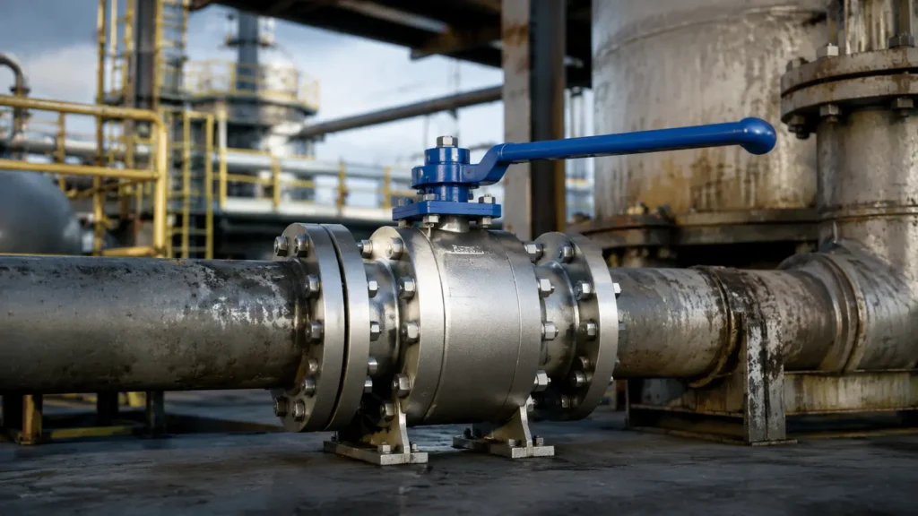
A custom metal seated ball valve is suitable when high temperature, abrasive particles, deposits, high differential pressure, or frequent operation may damage a standard soft seat. Before ordering, provide the complete fluid data, pressure-temperature combinations, maximum operating differential pressure, required leakage rate, stroke time, and expected cycle count. For a new or uncertain service, build a production-intent prototype and compare leakage, torque, coating condition, and internal wear before and after testing.CARILO’s forged metal seated ball valves can be used as a base for severe-service customization. When the fluid is clean and the seat material remains within its pressure, temperature, and chemical limits, a soft seated ball valve may provide tighter initial shutoff and lower operating torque.Final selection should be approved by qualified engineers using the real process conditions and the standards named in the purchase order. When Metal Seats Make Sense Metal seats are normally considered when a polymer seat may be cut, softened, deformed, extruded, chemically attacked, or filled with deposits. Slurry containing sand, catalyst, ash, scale, minerals, or metal particles Hot gas, steam, thermal oil, or refinery process fluid Coking, polymerizing, crystallizing, or sticky media High-cycle automated isolation Large valves operating against high differential pressure Processes in which solids collect around the ball or seats Applications requiring a qualified fire-tested valve design Metal seats are not the correct answer for every difficult application. Clean fluid may be sealed more tightly by PTFE, reinforced PTFE, PEEK, or another compatible soft-seat material. Continuous throttling may require a V-port, segmented ball, or purpose-built control valve. Cryogenic, oxygen, chlorine, hydrogen, and nuclear applications require separate reviews. Fluid Data A supplier cannot select the correct materials, coating, clearances, or actuator from a fluid name such as “slurry,” “steam,” or “dirty gas.” For solids and slurry, provide: Normal and maximum solids concentration Typical particle-size range Maximum particle size Particle hardness and shape Particle density Fluid viscosity at operating temperature Normal and maximum flow rate Whether the solids settle, pack, stick, or form lumps Large hard particles may chip a brittle coating or stop the valve from closing. Fine particles can enter seat pockets, springs, bearings, and stem clearances. Flat particles may bridge a narrow gap, while dense particles may collect at the bottom of the body after flow stops. Do not report only an average particle size. For example, a process may contain mostly particles between 50 and 300 μm but occasionally carry 1 mm pieces of scale. The fine particles may fill the seat pocket, while the larger pieces may damage the coating. For corrosive service, provide: Complete chemical composition Water and chloride content Acid, caustic, sulfur, or H2S concentration Gas and liquid phases Normal and upset temperature Possible condensation Cleaning and flushing chemicals The review may need to cover general corrosion, pitting, crevice corrosion, stress corrosion cracking, galvanic attack, hydrogen-related cracking, and corrosion beneath a damaged coating. For sticky or reactive media, explain: What causes the fluid to polymerize, coke, crystallize, or freeze How quickly deposits form Whether the deposits become hard or remain soft Whether air, moisture, cooling, or pressure loss starts the reaction How the line is cleaned before shutdown The cleaning fluid may create a more severe condition than the normal process. Steam can raise temperature, solvent can damage secondary seals, and water can react with process residue. Operating Conditions Normal operation is only one part of the valve duty. Maximum pressure, maximum temperature, maximum differential pressure, and the highest solids concentration may occur at different times. Minimum, normal, maximum, and design temperature Short-term temperature peaks Heating and cooling rate Normal and maximum line pressure Maximum differential pressure while opening Maximum differential pressure while closing Vacuum and reverse-pressure conditions Pressure and temperature during cleaning Emergency shutdown conditions Time normally held open or closed Line pressure is the pressure inside the valve. Differential pressure is the difference between the upstream and downstream sides. Differential pressure often has the greatest effect on seat load and actuator torque. A valve may normally operate with only 5 bar differential pressure but be required to close against the full line pressure during an emergency. That emergency condition must be included in the actuator calculation. The following table shows how one project may contain several different design cases. Illustrative Operating Case Line Pressure Temperature Operating Differential Pressure Valve Duty Normal production 65 bar 180°C 5 bar Remains open Normal isolation 65 bar 180°C 65 bar Closes Steam cleaning 8 bar 300°C 2 bar Operates twice Cold startup 20 bar 25°C 20 bar Opens after a 48-hour hold The values above are an illustrative example, not universal design limits. Replace them with the actual project conditions. External conditions also matter. State the expected pipeline vibration, pipe load, thermal expansion, flange or weld-end misalignment, outdoor temperature, dust, salt, rain, ice, insulation, heat tracing, flooding, fire, and seismic requirements. Floating or Trunnion Floating ball: The ball is held mainly by the seats. Line pressure moves it slightly toward the downstream seat to create shutoff. This design is compact and often economical for smaller valves and moderate differential pressure. As the sealing diameter and differential pressure increase, the ball is pushed harder against the downstream seat. This can raise contact stress, friction, wear, and operating torque. Trunnion-mounted ball: The ball is mechanically supported at the top and bottom. The seats move toward the ball under spring and pressure loading. This structure is commonly used for larger sizes, higher differential pressure, automated isolation, and DBB or DIB arrangements. Neither structure is automatically better. Selection should be based on seat load, torque, pressure direction, valve size, isolation function, and maintenance requirements. See CARILO’s floating and trunnion ball valve comparison for more detail. Seat Pressure Effect A trunnion valve may use single-piston-effect seats, double-piston-effect seats, or one of each. Single-piston-effect seat: Line pressure normally pushes the seat toward the ball. If the cavity pressure rises above the pressure on one side by the amount required by the design, the seat can move away from the ball and release pressure. Double-piston-effect seat: Pressure from either
Source Forged Ball Valves from China for EPC Project | Pre-Qualified Manufacturer with Track Record
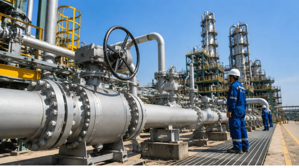
Yes, EPC contractors can source reliable forged ball valves from China, but the manufacturer must prove five things before receiving the order: the design suits the service, materials are traceable, the factory can complete the required tests, similar projects can be verified, and the valves and documents can be delivered on time.A sound purchase should be supported by at least five linked records: an approved valve data sheet, a complete bill of materials, traceable material certificates, serial-numbered test reports, and a controlled production schedule. A low price, factory video, or API certificate alone is not enough. Define the Service A supplier cannot select the correct valve from size and pressure class alone. The following 18 input groups should be included in the request for quotation: Fluid name and composition Gas, liquid, vapor, or mixed-phase condition Design and operating pressure Design and operating temperature Lowest possible temperature Maximum pressure difference across the closed valve Hydrogen sulfide, carbon dioxide, chloride, and water content Solid-particle size, hardness, and concentration Expected opening and closing cycles Required opening or closing time Manual, pneumatic, electric, or hydraulic operation Fail-open, fail-close, or fail-in-place action Fire-test, low-emission, sour-service, or cryogenic requirements Full-bore, pigging, DBB, or DIB requirements Flanged, butt-weld, socket-weld, or threaded ends Indoor, outdoor, buried, offshore, or marine installation Inspection and document requirements Packing and long-term storage requirements The maximum line pressure and the maximum pressure difference across the valve are not always the same. The second value affects operating torque and actuator size. “Natural gas” is also too general. Wet sour gas, dry sweet gas, hydrogen-rich gas, and gas containing particles may need different materials, seats, seals, tests, and cavity-pressure controls. A complete API 6D ball valve RFQ should list every condition that may change the valve design, testing scope, or price. Choose the Main Standard The purchase order should state one main valve standard, its edition, required addenda, and project-specific additions. Do not list several standards without explaining which one has priority. API 6D: API Specification 6D covers pipeline and piping valves, including design, materials, manufacturing, testing, marking, and documentation. The 25th edition has later updates, including Addendum 3 issued in March 2025.[1] API publishes addenda and errata after the main edition. The contract should name the exact issue instead of stating only “latest API 6D.”[2] When an API Monogram is required, check the legal company name, manufacturing address, product scope, and license status in API’s official directory.[3] API 608: API 608 applies to defined metal ball valves with flanged, threaded, and welding ends. API published the 7th edition in 2025.[4] API 608 and API 6D are not interchangeable. The project engineer should choose the standard that matches the valve type and service. ASME B16.34: This standard covers pressure-temperature ratings, materials, dimensions, testing, marking, and nondestructive examination for many cast, forged, and fabricated valves. ASME currently lists the 2025 edition.[5] ISO 17292: ISO 17292 covers metal ball valves for petroleum, petrochemical, natural-gas, and related industrial applications. Its size, pressure, and end-connection limits must be checked before it is used as the governing standard.[6] Set the Test Rules Pressure testing should follow the main valve standard and the purchase order. ISO 5208 is intended to be used with a valve product standard; where requirements differ, the product standard takes priority.[7] API 598, API 607, API 608, and API 641 have different purposes. They should not be grouped together as one general “API test certificate.”[8] The order should state: Test standard and edition Test medium Test pressure Test duration Valve position Pressure direction Allowed leakage Leakage measurement method Witness or hold points Required test records Fire testing: A fire-tested valve is checked for pressure containment and permitted internal and external leakage during and after a defined fire exposure. ISO 10497 is an international fire type-test standard for valves.[9] The fire-test certificate must match the actual valve type, body construction, seat design, stem sealing, size range, and pressure class. A certificate for a small two-piece floating valve does not automatically qualify a large three-piece trunnion valve. Low-emission testing: ISO 15848-1 covers valve type testing for fugitive emissions.[10] ISO 15848-2 covers production acceptance testing.[11] A packing supplier’s certificate does not prove that the complete valve has passed a low-emission test. Stem diameter, stem finish, packing chamber, pressure, temperature, and operating cycles all affect leakage. Choose Forged or Cast Construction A forged body is shaped under pressure before machining. A cast body is made by pouring molten metal into a mold. Forged construction is often selected for compact high-pressure valves, low-temperature service, critical isolation, or projects that require forged pressure-containing parts. Forging can provide controlled mechanical properties, but it does not remove every risk. Forgings can still have: Laps and cracks Internal inclusions Wrong heat treatment Excessive hardness Poor impact toughness Material mix-ups Machining damage Large cast bodies may be more practical for some sizes and pressure classes. The choice should depend on pressure, temperature, material, body shape, inspection level, cost, lead time, and maintenance requirements. See the detailed forged versus cast valve body comparison for the main manufacturing and inspection differences. Choose Floating or Trunnion Design Floating ball valves: The ball can move slightly under pressure and is pushed toward the downstream seat. This design is commonly used where size, pressure, seat load, and torque remain within the manufacturer’s proven range. Check: Maximum valve size and pressure class Seat load at full pressure difference Breakaway torque Seat deformation Stem strength Body-cavity pressure relief Required leakage rate For clean service requiring tight shutoff, review the available forged soft-seated ball valve range. Trunnion-mounted ball valves: The ball is supported by upper and lower bearings or trunnions. The seats move to seal against the ball. This design is commonly used for: Large sizes High pressure Pipeline isolation Emergency shutdown Powered actuation DBB or DIB service The drawing should show the trunnion bearings, seat springs, seat directions, drains, vents, sealant-injection points, and cavity-pressure relief method. A detailed API 6D trunnion ball valve guide can help buyers prepare the required data sheet and
Get Certified API 6D Ball Valves with Full MTR Traceability | Bulk Order Procurement Service
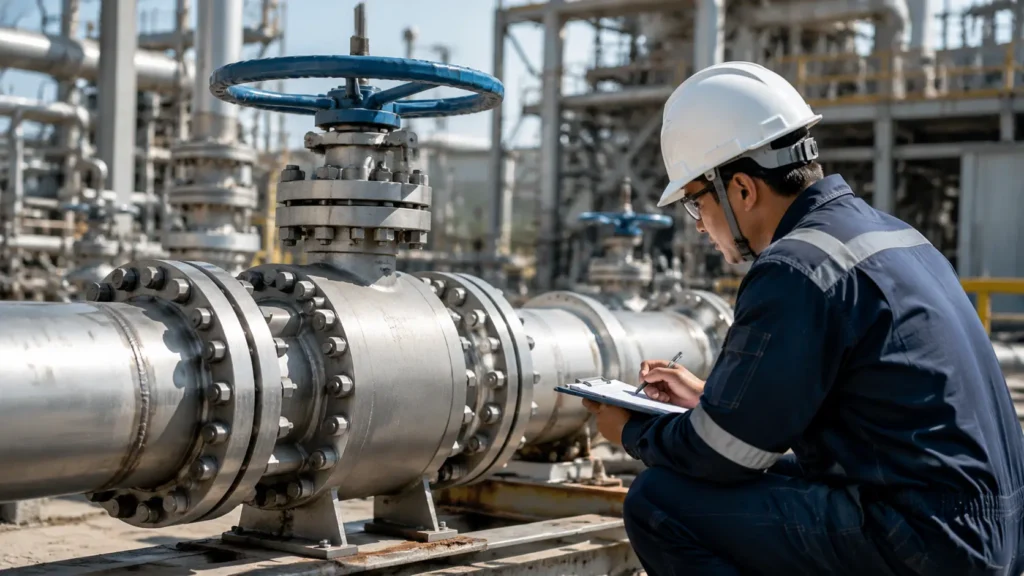
To buy API 6D ball valves in bulk, verify the actual licensed factory, define the complete valve specification before production, and require each valve serial number to match its material, inspection, test, actuator, and shipment records. An API certificate alone does not prove that the offered valve suits the project or that its materials are fully traceable. For a 100-valve order, one repeated error in the bore, seat material, nameplate, drain position, or actuator interface can affect all 100 units. Checking the factory, drawings, first completed valve, test records, and final data book before shipment is much cheaper than correcting the same error after delivery. Before placing the order, confirm these five points: The actual manufacturing facility holds the required active API 6D Monogram license. The valve design matches the fluid, pressure, temperature, installation, and isolation duty. Critical components can be traced to applicable Material Test Reports. Inspection, testing, documentation, and deviation rules are written into the purchase order. Every finished valve has its own traceable serial-number record. Verify the API 6D License “API 6D compliant” and “API 6D Monogrammed” are not the same. A supplier may state that a valve is designed to API 6D. That is the supplier’s own conformity claim. It does not prove that API has licensed the factory to apply the API Monogram. The API Monogram is a voluntary licensing program. The mark can be applied only to new conforming products made by the licensed organization at the licensed facility under a quality system that meets API Spec Q1.[1] Item What to check Legal manufacturer The company name must match the API license. Factory address The licensed address must match the actual production site. License scope The license must include the relevant API 6D product scope. License status The license must be active when the valve is manufactured and marked. API marking The nameplate and marking must follow the applicable program rules. Subcontracted work The licensed manufacturer must control outsourced processes and remain responsible for the product. Use the API Composite List to check the current license record instead of relying only on a PDF certificate supplied by the seller.[2] A certificate from a sister company, sales office, trading company, or different factory is not enough. As a practical control, check the license at three stages: during supplier approval, before purchase-order award, and before shipment release. A valid license also does not prove that the factory has experience with every size, material, or service. For a large, high-pressure, hydrogen, sour-service, fully welded, duplex, or metal-seated order, ask for records from comparable projects. Useful evidence includes: Similar valve size and pressure class Similar body and seat design Similar body and trim materials Similar actuator package Similar inspection and testing scope Previous Manufacturing Record Books For a wider supplier review, use the ball valve factory audit guide to check production, material control, test facilities, and document management. State the Exact Standards Do not write only “API 6D latest edition” in the RFQ. API Specification 6D is in its 25th Edition. Addendum 3 was issued on March 5, 2025, with an API Monogram Program effective date of September 5, 2025.[3] Design, manufacture, inspection, testing, marking, and documentation shall comply with API Specification 6D, 25th Edition, including Addendum 3 and applicable errata. The order may also refer to: ASME B16.34 for pressure-temperature ratings, materials, NDE, testing, and marking ASME B16.5 or B16.47 for flanged ends ASME B16.10 for face-to-face or end-to-end dimensions ASME B16.25 for butt-welding ends API 6DX for actuator sizing and mounting where applicable API 6FA, API 607, or ISO 10497 for the applicable fire qualification API 641 or ISO 15848 for fugitive-emission requirements ISO 15156 or another project-approved sour-service standard Local pipeline, pressure-equipment, and hazardous-area rules ASME B16.34:2025 covers pressure-temperature ratings, materials, dimensions, tolerances, nondestructive examination, testing, and marking for the valve types within its scope.[4] The purchase order should also say which document takes priority when requirements conflict. A practical order is: Purchase order and approved amendments Project valve specification Approved valve data sheet Project material, inspection, and testing requirements API 6D Other referenced standards Approved manufacturer drawings and procedures Freeze the standard editions when the order is placed. A later revision should not change an existing order unless both parties approve its effect on design, price, testing, documents, and delivery. Send a Complete RFQ An inquiry such as “20 pieces, 12-inch, Class 600 API 6D ball valves” contains only four basic data points: quantity, size, pressure class, and valve type. A usable project RFQ normally needs more than 20 fields covering the fluid, pressure, temperature, bore, materials, seats, actuator, testing, documents, packing, and delivery. Category Information to provide Quantity Total quantity and tag breakdown Size NPS or DN Pressure rating ASME Class or PN Valve type Floating or trunnion mounted Body design Side-entry, top-entry, two-piece, three-piece, or fully welded Bore Full bore, reduced bore, or stated minimum opening Ends RF, RTJ, butt weld, or another connection Fluid Full composition rather than only “gas” or “oil” Pressure Design, operating, shut-off, and maximum differential pressure Temperature Normal, design, upset, ambient, and minimum metal temperature Materials Body, closure, ball, stem, trunnion, seats, bolting, and soft parts Seat function SPE, DPE, sealing direction, cavity relief, DBB, or DIB Operation Lever, gearbox, pneumatic, hydraulic, or electric Installation Aboveground, buried, indoor, offshore, or another environment Inspection Review, witness, hold points, and third-party involvement Testing Routine API 6D tests and any project-added tests Documents Drawings, calculations, MTRs, reports, certificates, and final data book Packing Export, seaworthy, long-term storage, or project-specific packing Delivery Required date, destination, and allowed shipment batches The buyer should provide the real operating conditions. The supplier should return the proposed design, complete bill of materials, torque data, pressure-temperature rating, qualification records, inspection scope, and a separate deviation list. Any deviation from the inquiry, data sheet, project specification, or referenced standard shall be listed separately. Requirements not identified as deviations shall be considered accepted. The custom API 6D ball valve RFQ guide provides a practical list of the
Order Trunnion Mounted Ball Valves for Oil Pipeline Project | Full Production and Delivery Timeline
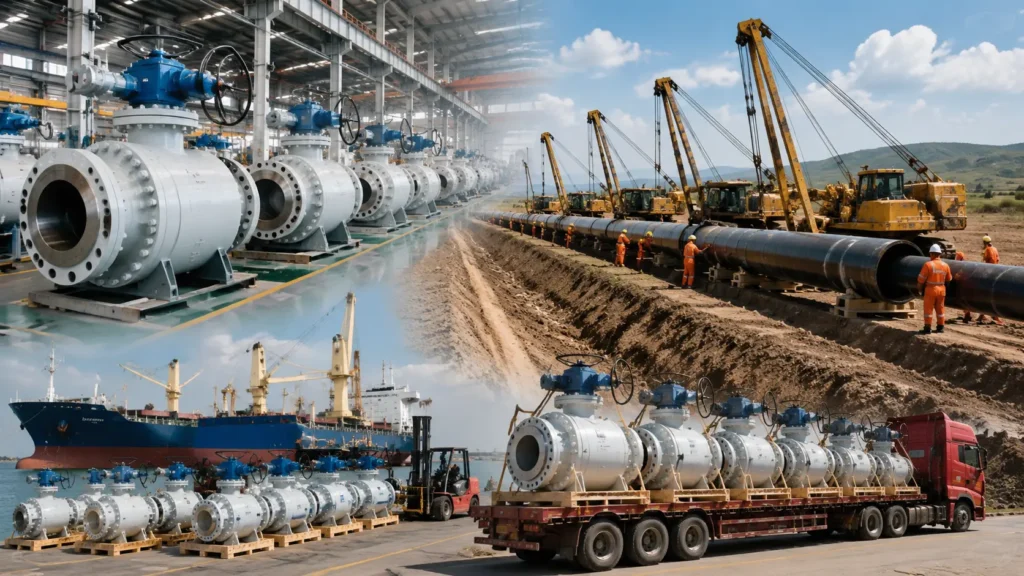
A standard trunnion mounted ball valve order normally needs about 16 to 24 weeks from the agreed contractual starting date to factory release. Large sizes, high pressure classes, sour service, special materials, weld overlay, powered actuators, third-party inspection, or special testing can extend the factory lead time to 24 to 40 weeks or longer. Ocean freight and inland delivery must be added separately. The 16-to-24-week range is most useful for early planning of a small or medium order, such as 1 to 10 valves using common carbon steel materials, standard soft seats, routine production tests, and no major design changes after order placement. It is a planning example, not an API, ISO, or ASME requirement. Planning Item Standard Order Assumption Order quantity About 1–10 valves Material Common carbon steel with standard trim Operation Manual gearbox or standard powered actuator Drawing review One or two main comment rounds Testing Routine production testing without unusual project tests Factory lead time About 16–24 weeks The purchase order should define a clear starting date, called Day 0. Day 0 may be the date the supplier accepts the purchase order, receives the advance payment, closes the main technical questions, or receives approval to buy long-lead materials. The contract must also define the delivery point. Factory completion, factory release, EXW availability, handover to the carrier, vessel departure, port arrival, customs release, and delivery to site are different milestones. Confirm the Pipeline Service Do not select a pipeline valve from nominal size and pressure class alone. The manufacturer needs the real operating conditions to choose the body, seats, seals, ball surface, gearbox, and actuator. Provide the following information with the request for quotation: Fluid type, such as crude oil, diesel, gasoline, condensate, or multiproduct service Design pressure and normal operating pressure Maximum pressure difference during opening and closing Design temperature and minimum design metal temperature Minimum and maximum ambient temperature Water, sand, scale, wax, or other contaminants H₂S content, chloride level, and presence of free water Flow direction and operating frequency Required opening and closing time Aboveground or underground installation Hazardous-area classification Pigging and inline inspection requirements Expected operating life Normal operating pressure and maximum closing pressure difference are not the same. A valve may normally operate at 60 bar but need to close against a higher pressure difference during an emergency. If the actuator is sized only for normal operation, it may not close when isolation is needed. The fluid description should be more specific than “oil.” Crude oil, diesel, gasoline, condensate, and heavy fuel oil may have different effects on polymer seats and elastomer seals. Identify free water, dissolved gas, aromatic hydrocarbons, solids, cleaning chemicals, and pipeline additives where relevant. For buried valves, also provide: Burial depth Soil and groundwater conditions Stem-extension height Pipeline coating type Cathodic-protection details Required position of drain, vent, and sealant lines A valve operated weekly has different wear and torque conditions from an emergency shutdown valve that may stay in one position for several years. For long-idle valves, ask the manufacturer to consider deposits, seat aging, seal compression, temperature, and higher breakaway torque. For more selection details, see the API 6D trunnion mounted ball valve guide. Choose the Valve Construction In a trunnion mounted ball valve, the ball is supported at the top and bottom. The seats move toward the ball to form the seal. This construction is commonly used for large sizes, high pressures, high pressure differences, remote operation, buried pipelines, and piggable mainlines. The purchase specification should state: Two-piece or three-piece body Bolted or fully welded body Side-entry or top-entry construction Full or reduced bore Flanged or butt-weld ends Soft or metal seats Manual, electric, hydraulic, pneumatic, or gas-over-oil operation A fully welded valve has fewer external body joints and is often used for buried mainline service. However, internal repairs are more difficult, and the manufacturer must control welding, heat input, dimensional distortion, and nondestructive examination. A top-entry valve may allow the seats and ball to be removed from above without taking the complete valve out of the pipeline. This only helps when the site has enough lifting space, safe access, drainage, and pressure isolation. A side-entry valve is usually easier to manufacture and repair in a workshop, but major internal work may require removal from the pipeline. Compare the options in this side-entry versus top-entry ball valve guide. Also confirm: Blowout-resistant stem design Antistatic device Emergency stem and seat sealant injection Drain and vent connections Lifting lugs and support feet Position indicator and locking device Stem-extension construction Maximum permitted external pipe loads Define the Bore Do not write only “full bore.” State the required minimum finished bore and ask the manufacturer to show the complete flow path on the drawing. Check the valve bore against: Actual pipe inside diameter Pipe wall thickness and tolerance Internal coating thickness Ball-port diameter Seat-opening diameter Butt-weld-end transition Pig and inline inspection-tool diameter Maximum permitted internal step and misalignment A valve described as full bore may not exactly match a thick-wall or internally coated pipeline. The approved drawing should show the minimum bore through the ball, both seat openings, body, and end connections. For piggable pipelines, the operator or inspection-tool supplier should confirm the allowed bore reduction, ovality, internal step, protrusion, and offset. Freeze the bore before major body materials are ordered. A change made after forging production starts may add about 6 to 16 weeks if replacement material is required. This is a project-planning range and depends on size, material, and forging availability. Define the Seat Function Seat design controls sealing direction and the way pressure is released from the body cavity. Common arrangements include: Two single-piston-effect or self-relieving seats Two double-piston-effect seats One self-relieving seat and one double-piston-effect seat SPE and DPE describe how an individual seat reacts to pressure. DBB and DIB describe the isolation function of the complete valve. They are not interchangeable terms. A self-relieving seat can allow excess cavity pressure to return to the pipeline when the required pressure difference is reached. A double-piston-effect seat
Best Ball Valves for Hydrogen Service | Material Embrittlement Prevention and Certified Supplier List
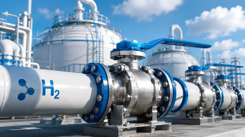
The best hydrogen ball valve is the valve whose materials, pressure range, temperature range, seals, cycle life and certificate match the real operating conditions. For an H35 or H70 refuelling station, the exact valve configuration should be covered by ISO 19880-3. For industrial hydrogen systems, 316L bodies and PEEK seats are common starting choices, but the stem, springs, O-rings, welds, cavity relief and actuator also need to be checked. This article mainly covers gaseous hydrogen used in electrolysers, compressors, storage systems, tube trailers, pipelines and refuelling stations. Liquid hydrogen is stored near −253°C and requires a dedicated cryogenic valve rather than a standard gaseous-hydrogen valve.[3] CARILO’s forged cryogenic ball valves show common cryogenic features such as an extended stem and low-temperature sealing parts, but suitability for liquid hydrogen must be confirmed for the exact valve. Quick Selection Application Starting Valve Type Main Checks Electrolyser outlet 316L floating ball valve with a qualified soft seat Moisture, electrolyte carryover, purity, pressure and low-pressure sealing Compressor inlet Full-port floating ball valve Flow capacity, pressure loss, gas cleanliness and pulsation Compressor discharge High-pressure floating or trunnion ball valve Discharge temperature, full pressure difference, decompression rate and cycles H35 station ISO 19880-3-qualified valve Certificate scope, minimum temperature, cycle class and leakage limit H70 station ISO 19880-3-qualified valve for the actual station pressure Bore, connection, temperature, pressure cycles and actuator torque Tube trailer ISO 23826 or TPED-qualified ball valve Size-specific approval, vibration, connection and transport rules Industrial plant Low-emission, fire-tested valve with qualified materials Gas impurities, process temperature, piping code and shutdown duty Hydrogen pipeline Full-bore trunnion ball valve Fatigue, cavity relief, welds, seat direction and DBB/DIB function Liquid hydrogen Dedicated cryogenic valve Low-temperature materials, extended stem, thermal cycles and cavity relief ISO 19880-3 covers safety and testing requirements for high-pressure gas valves used in gaseous-hydrogen stations up to the H70 designation.[1] It does not certify every valve used in an industrial hydrogen plant. ISO develops standards but does not certify products. Certification is written assurance from an independent certification body that a specific product meets stated requirements.[2] Pressure Reference Pressure Level Equivalent Value 35 MPa 350 bar 50 MPa 500 bar 70 MPa 700 bar 100 MPa 1,000 bar 103.4 MPa 1,034 bar These are direct unit conversions. They do not show whether a valve is certified for a particular H35 or H70 station location. A valve marked 700 bar may still be unsuitable if its certificate does not cover the required bore, connection, temperature, cycle class or operating function. Service Data Give the supplier the real operating conditions instead of asking only for a “hydrogen valve.” Hydrogen concentration Complete gas composition Normal operating pressure Maximum allowable working pressure Design pressure Maximum pressure difference across the valve Minimum and maximum fluid temperature Minimum and maximum ambient temperature Normal and maximum flow Required bore or flow coefficient Cycles per day Total design cycles Required internal leakage Required external leakage Manual or automatic operation Required fail position Applicable standards and local rules A 30-bar electrolyser outlet and a 700-bar refuelling-station valve are both used with hydrogen, but they should not use the same design or purchasing specification. Example: Electrolyser Outlet The following values are an example only. They are not universal design limits. Item Example Value Normal pressure 30 bar Design pressure 40 bar Fluid temperature 5°C to 45°C Valve size DN15 Expected operating life 10,000 cycles Gas condition High-purity hydrogen with possible moisture Starting design 316L floating ball valve with a qualified soft seat In this example, cleanliness, moisture, electrolyte carryover and low-pressure seat sealing may matter more than buying a 700-bar valve. Example: Compressor Discharge The following values show how pressure, temperature and cycles must be considered together. Item Example Value Normal pressure 450 bar Maximum working pressure 500 bar Fluid temperature −20°C to 85°C Valve bore 8 mm Expected operating life 30,000 cycles Operating condition Full pressure difference Starting design High-pressure trunnion or reinforced floating ball valve A valve with a 700-bar room-temperature rating may still be unsuitable if it cannot operate at 85°C, complete 30,000 full-pressure cycles or provide acceptable torque at the minimum temperature. Example: H70 Station The following example is a project specification, not a statement that every ISO 19880-3 valve must meet the same values. Item Example Value Nominal hydrogen level 70 MPa / 700 bar Minimum valve temperature −40°C Valve bore 8 mm Required operating life 100,000 cycles Operation Automatic shut-off Fail position Fail closed Required evidence ISO 19880-3 certificate for the exact configuration The buyer should confirm that the certificate covers the exact pressure, temperature, bore, connection, seat, seal and cycle class. A product name containing “700” does not prove H70 approval. Gas Quality Pure, dry hydrogen is different from wet industrial hydrogen. Possible contaminants include: Water Oxygen Carbon monoxide Carbon dioxide Methane Ammonia Hydrogen sulphide Chlorides Compressor oil Electrolyte droplets Solid particles Water can increase corrosion. Hydrogen sulphide introduces sour-service cracking risks. Chlorides can attack some stainless steels. Oil can damage seals or contaminate fuel-cell hydrogen. Particles can scratch the ball and cut a soft seat. A valve selected for dry, high-purity hydrogen should not automatically be used with wet refinery hydrogen or hydrogen containing corrosive impurities. Hydrogen Blends A natural-gas valve should be reassessed before hydrogen is added to the gas. Check the hydrogen percentage and partial pressure. Check total pressure and pressure cycles. Review the body, stem, bolts and spring materials. Review packing and elastomer compatibility. Check the existing leakage class. Consider valve age, repairs and service history. Hydrogen can increase fatigue-crack growth in some carbon steels. The result depends on material condition, stress, hydrogen pressure and loading frequency.[7] A low hydrogen percentage alone is not enough to approve an existing natural-gas valve. Main Failure Risks A metal part cracks. A seat deforms or wears. Hydrogen leaks through the stem or body joint. An O-ring blisters during rapid depressurisation. Hydrogen slowly passes through a polymer. Pressure becomes trapped in the valve cavity. The actuator cannot move the valve under full pressure. Released hydrogen finds
Request a Quote for Custom API 6D Ball Valves | Specify Your Size, Pressure Class, and Material
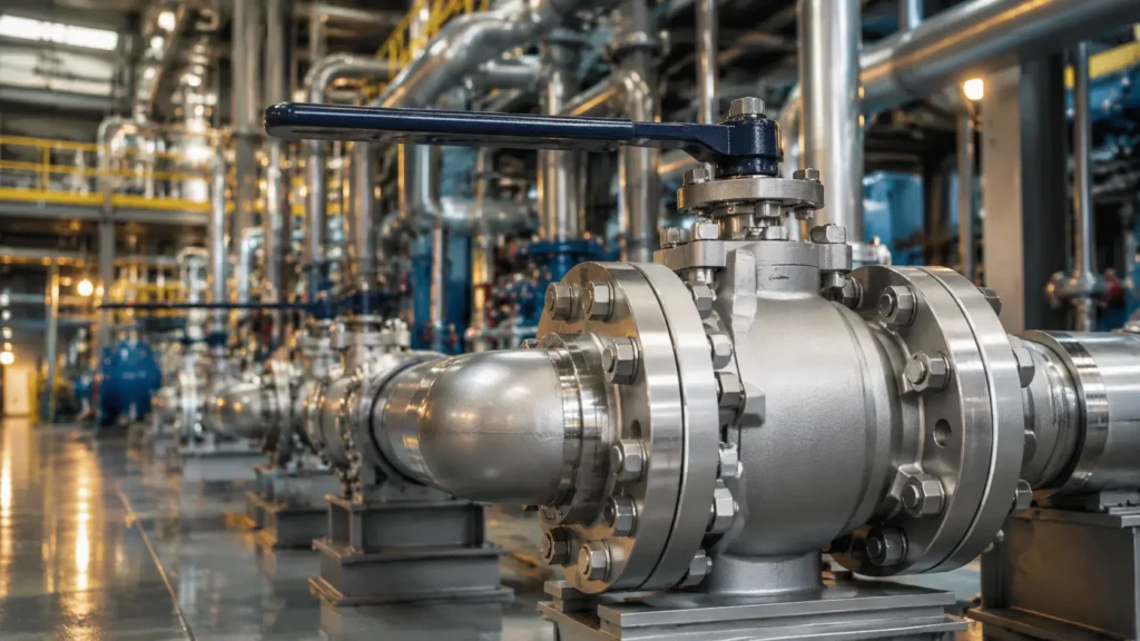
To get an accurate quote for a custom API 6D ball valve, provide the size, quantity, pressure class, design pressure, temperature range, fluid composition, body and trim materials, bore type, end connection, seat design, operator, testing scope, documents, and delivery date. Size, pressure class, and body material are enough for a rough budget price. They are not enough for final valve selection. A 12-inch Class 600 carbon-steel valve for clean natural gas may use soft seats and a manual gearbox. A valve of the same size handling wet sour gas may need different stem materials, decompression-resistant seals, extra inspection, fugitive-emission testing, and a powered actuator. Common Project Examples — Not the Full API 6D Product Range RFQ Item Common Project Examples Valve size NPS 2–48 / DN 50–1200 Pressure class ASME Class 150, 300, 600, 900, 1500, or 2500 Order quantity 1 prototype or 2–50 production valves Example temperature range −29°C to 120°C Example differential pressure 0–100 bar Operator Lever, gearbox, pneumatic, hydraulic, gas-over-oil, or electric These values are common project examples, not universal design limits. Actual size, pressure, temperature, bore, torque, and material limits depend on the selected valve design and project specification. For a basic introduction to pipeline valve construction, see this guide to API 6D ball valves. Confirm the Standards State the exact API 6D edition, addenda, errata, and project specification in the request for quotation. Do not write only “latest API 6D,” because the standard may change after the supplier submits its price. API Specification 6D, 25th Edition, was published in November 2021. Addendum 3 was issued on March 5, 2025.[1] A clear RFQ statement is: Design and manufacture in accordance with API Specification 6D, 25th Edition, November 2021, including the addenda and errata specifically listed in this purchase specification. ISO 14313:2025 supplements API 6D, 25th Edition. It covers axial, ball, check, gate, and plug valves in ASME Classes 150, 300, 600, 900, 1500, and 2500.[2] Include ISO 14313 only when required by the project, end user, national rules, or pipeline design basis. When several documents apply, state which one takes priority. For example: In case of conflict, the purchase order, project valve specification, approved valve data sheet, API 6D, and other referenced standards shall apply in that order. The supplier shall report every conflict or deviation before production. Do not allow the supplier to resolve technical conflicts without written approval. A small difference in seat arrangement, material grade, testing, or valve length can affect installation and safety. For a summary of pressure ratings, connections, and material options, review these API 6D ball valve specifications. Check the API Monogram “Designed to API 6D” and “API 6D Monogrammed” do not mean the same thing. The API Monogram Program licenses qualified manufacturers to apply the registered API mark to products made under the applicable API specification and quality requirements.[3] If the Monogram is required, write: The valve shall be manufactured, tested, marked, and documented at a facility holding a valid API 6D Monogram license for the offered product. Check the actual manufacturing site, not only the company name. API provides a directory for checking current licenses and registered factory locations.[4] Verify: Legal company name Manufacturing-site address License number License status Licensed product scope Whether the quoted factory matches the licensed factory An ISO 9001 certificate, distributor letter, API Spec Q1 certificate, or expired API license does not replace a valid API 6D Monogram license when the purchase order requires Monogrammed valves. State the Size and Quantity Provide the nominal size in NPS, DN, or both. Do not provide only the pipe outside diameter. Item Size Class End Type Operator Quantity 1 NPS 4 / DN 100 300 Raised-face flange Lever 8 2 NPS 8 / DN 200 600 Ring-type-joint flange Gearbox 4 3 NPS 16 / DN 400 900 Butt welded Pneumatic actuator 2 Use separate line items when the valves have different materials, bores, body designs, seat arrangements, end connections, operators, coatings, or testing requirements. Quantity affects the unit price because a custom order may require: Engineering calculations Drawing preparation Machining programs Special fixtures Inspection procedures Document preparation A one-valve order carries all these setup costs on one unit. A ten-valve order spreads some of the engineering and setup cost across the full quantity. For large valves, also provide: Maximum permitted weight Available installation space Required operator position Maximum height above the pipe centerline Lifting restrictions Required support points Maintenance clearance Ask the supplier to state the bare-valve weight, operator weight, total assembled weight, shipping dimensions, lifting points, and center of gravity where needed. Give the Pressure and Temperature Pressure class is not a direct pressure value. Class 600 does not mean that the valve is rated to only 600 psi. The allowable pressure depends on the body material, temperature, design standard, and end connection. ASME B16.34 covers pressure-temperature ratings, materials, examination, testing, and marking for applicable flanged, threaded, and welding-end valves.[5] Provide: ASME pressure class Design pressure Normal operating pressure Maximum operating pressure Maximum differential pressure during opening Maximum differential pressure during closing Minimum and maximum design temperature Minimum and maximum operating temperature Minimum and maximum ambient temperature Illustrative RFQ Data — Final Values Must Be Confirmed for the Project Parameter Example Valve size NPS 12 / DN 300 Pressure class ASME Class 600 Design pressure 100 bar Normal operating pressure 70 bar Maximum opening differential 70 bar Maximum closing differential 100 bar Design temperature −29°C to 120°C Normal operating temperature 40°C These figures are examples only. The manufacturer must check the pressure rating against the selected body material, seats, seals, bolting, and end connections. Differential pressure is important for operating torque. A valve may normally have similar pressure on both sides. During emergency isolation, one side may remain fully pressurized while the other side falls close to zero. Also report temporary conditions that may be more severe than normal operation: Emergency shutdown Pressure surge Gas blowdown Rapid decompression Cold start-up Steam cleaning Heating of trapped liquid Describe the Fluid “Oil,” “gas,” and “water” are
Best Valve Brands for Steam Application in Power Plants | Gate vs Globe vs Ball Valve Selection Heat Map
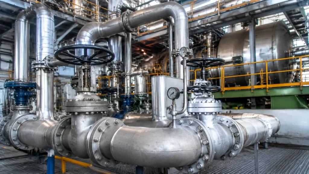
For power plant steam systems, use a gate valve as the first option for large-bore isolation, a globe or angle control valve for pressure and flow control, and an engineered metal-seated ball valve for fast or frequent on/off service. Flowserve Edward, Velan and KSB are practical brands to compare for high-pressure gate and globe valves. Emerson Fisher, Emerson Sempell and IMI Critical Engineering are commonly evaluated for turbine bypass, pressure reduction and steam conditioning. MOGAS, Valmet Neles and CARILO can be evaluated for metal-seated rotary isolation when the exact model has suitable pressure-temperature ratings, hot-cycle data and comparable steam references. The brand name is only the start of the selection. The approved valve must match the actual steam state, design temperature, maximum differential pressure, operating frequency, closing time, leakage limit, pipe material and maintenance plan. This article mainly applies to fossil-fuel and combined-cycle power plants. Nuclear safety-related valves require additional design qualification, quality assurance, documentation and regulatory review. A valve accepted for auxiliary steam should not automatically be approved for main steam, hot reheat or turbine bypass service. Safety note: High-energy steam can cause fatal burns and sudden pressure releases can occur at valves, flanges and other steam-system components. Valve sizing, material selection, actuator sizing, piping-code compliance and site operation must be reviewed by qualified engineers.[1] ASME B31.1 sets requirements for piping systems commonly found in electric power generating stations.[2] Nuclear valves that perform safety functions require additional qualification beyond ordinary industrial valve selection.[3] Selection Heat Map The table shows the normal first valve type to evaluate. It does not mean that every valve of that type is suitable for the stated service. Application Gate Valve Globe Valve Metal-Seated Ball Valve Main Risk to Check Main steam isolation Normal first choice Possible for smaller sizes Project-specific option Thermal binding, pressure locking, creep and actuator thrust Hot reheat isolation Normal first choice Possible Project-specific option High temperature, thermal cycling and material capability Cold reheat isolation Good Possible Good for frequent operation Start-up condensate and operating frequency Boiler stop service Common for large-bore isolation Globe or stop-check design may be required Uncommon Boiler-code boundary, full differential pressure and required function Turbine bypass Not suitable for normal control Normal first choice Special control design only Choked flow, noise, wet steam, erosion and desuperheating Steam pressure reduction Poor Normal first choice Purpose-designed rotary trim only Pressure ratio, trim velocity, noise and low-load stability Warm-up line Poor for controlled throttling Good for controlled heating Good for on/off duty Downstream heating rate and condensate removal Drain isolation Possible Good Good for frequent cycling Flashing condensate, erosion and leakage after cycling Vent isolation Possible Good Good for rapid operation Outlet velocity, noise and safe discharge location Soot-blower steam Possible Special globe or soot-blower valve Possible with proven cycle data OEM system design, cycle life and tight shutoff Large-bore isolation Normal first choice Heavy and costly Possible but often expensive Installed weight, actuator size and maintenance access Emergency isolation Usually slower Depends on actuator and travel Often suitable for rapid isolation Transient pressure, closing time, fail action and stored energy A quarter-turn ball valve may close quickly, but rapid closure is not automatically safe. The piping engineer must check the pressure transient, allowable closing time, actuator fail action and body-cavity pressure relief. Performance Area Gate Valve Globe Valve Metal-Seated Ball Valve Full-open pressure loss Low Relatively high Low in full-bore designs Normal throttling ability Poor Excellent with correct trim Limited unless purpose-designed Typical travel characteristic Multi-turn, normally slower Linear travel Quarter-turn, often faster Large-size availability Excellent Available but heavy Good, with rapidly increasing cost High-cycle isolation Moderate Moderate to good Good when correctly engineered High-pressure-drop control Poor Excellent with engineered trim Special control designs only In-line maintenance after isolation Depends on bonnet and internal design Often practical in top-entry designs Depends on top-entry, side-entry or welded-body construction Main failure concern Binding, seat damage and actuator overload Trim erosion, noise and unstable control Coating wear, torque rise and cavity overpressure Typical Hydraulic and Travel Ranges The figures below are broad screening ranges for conventional designs. They are not acceptance limits. Actual pressure loss and travel time depend on valve size, port geometry, trim, actuator output, gearing, available power and the permitted closing transient. Valve Type Illustrative Full-Open Resistance Coefficient K Illustrative Actuated Travel Time Practical Meaning Full-bore ball valve About 0.05–0.2 About 1–15 seconds with pneumatic or hydraulic actuation Low full-open loss and fast quarter-turn movement Fully open gate valve About 0.1–0.3 About 30–180 seconds for many large motor-operated packages Low loss, but long stem travel makes rapid operation less practical Y-pattern globe valve About 2–5 About 3–30 seconds with pneumatic or hydraulic actuation Lower loss than a conventional globe body while retaining control capability Conventional globe valve About 6–12 About 3–30 seconds with pneumatic or hydraulic actuation; motor-operated units may take 20–120 seconds Higher permanent loss, but better throttling and pressure-reduction capability A resistance coefficient is only an approximation. Reducers, partial bore, cages, multistage trim and downstream fittings can change the installed pressure loss substantially. Actual opening and closing time must also be confirmed for the complete valve-actuator package. For rotary valves, the ball valve pressure-drop and Cv guide explains why bore geometry and flow coefficient should be checked instead of assuming that every ball valve has the same hydraulic performance. Define the Service First A reliable valve quotation starts with a clear service definition. Avoid descriptions such as “high pressure steam valve” or “high-cycle valve” without measurable operating data. Valve Duty For fully open or fully closed isolation, compare gate and ball valves. For continuous intermediate travel, use a globe valve or a purpose-designed rotary control valve. For a valve that opens slowly during plant start-up, treat the service as a control duty even if the final position is fully open. For a control valve that must also isolate, specify both control performance and the required closed-seat leakage. A normal gate valve should not be used for continuous throttling. A standard round-port ball valve should not
Top Ball Valve Testing Equipment and Standards | Hydrostatic vs Pneumatic vs Cryogenic Test Bench Comparison
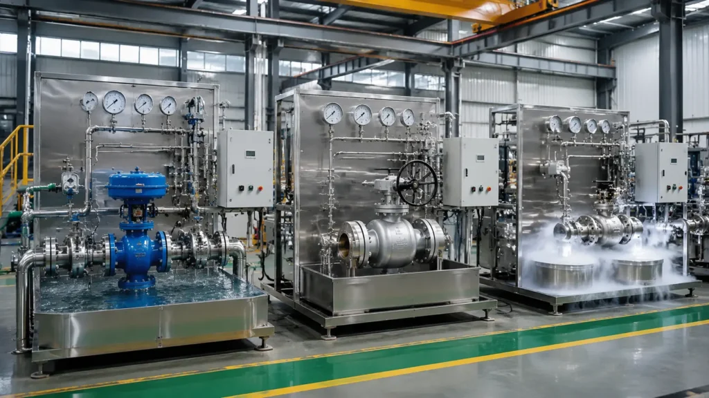
For most ball valve factories, the practical setup is a hydrostatic bench for shell and high-pressure seat tests, plus a pneumatic station for sensitive gas-leak testing. A cryogenic bench is needed when the valve must prove sealing, operation and torque performance at a specified low temperature. Do not select a test bench by pressure rating alone. Check the effective test diameter, clamping force, valve weight, connection type, pressure range, minimum measurable leakage, test direction and required output per shift. Quick Comparison Item Hydrostatic Bench Pneumatic Bench Cryogenic Bench Main purpose Shell and high-pressure liquid seat tests Low-pressure gas seat and external leak tests Leakage, operation and torque tests at low temperature Common medium Treated water or another approved liquid Air, nitrogen, helium or another specified gas Liquid nitrogen or cold gas for cooling; gas for pressure testing Leak sensitivity Moderate High High at the specified temperature Main risk High pressure, heavy valves and large separating force Stored energy in compressed gas Compressed gas, extreme cold and oxygen displacement Typical test speed Fast Medium Slow Post-test work Drain and dry the valve Vent the gas safely Warm, dry and inspect the valve Best use Routine factory testing Gas service and low leakage limits LNG and other low-temperature services A low-pressure gas seat test is not the same as a high-pressure pneumatic shell test. The first checks small seat leaks. The second stores much more energy and requires a test area designed for possible equipment or valve failure. Example Test Times The figures below are planning examples for medium-size valves. They are not standard-required test times. Actual times depend on valve size, pressure, filling volume, holding time and customer requirements. Example Item Hydrostatic Test Pneumatic Test Cryogenic Test Setup and connection 3–10 minutes 3–10 minutes 10–30 minutes Stabilization 2–10 minutes 3–15 minutes 30–120 minutes Example total cycle 10–30 minutes 10–40 minutes 2–6 hours Main recorded data Pressure, time and visible or collected leakage Pressure, time, temperature and gas leakage Pressure, temperature, leakage, cycles and torque Best Bench by Application Valve or Service Recommended Setup Important Functions Standard industrial ball valves Hydrostatic bench plus low-pressure gas station Shell, liquid seat, gas seat and operating tests API 6D pipeline valves Horizontal hydrostatic bench with several test ports Bidirectional seat, cavity, drain, vent and torque tests Small high-pressure valves Compact high-pressure bench Small test volume, fine pressure control and suitable adapters Metal-seated valves Hydrostatic and pneumatic bench Measured leakage and torque recording High-purity gas valves Clean pneumatic station Dry gas, clean tubing and verified drying Very low leakage limits Helium leak station Background control and a calibrated detector LNG and low-temperature valves Cryogenic bench Controlled cooling, temperature recording, gas leakage and torque tests Tests a Ball Valve May Need Test What It Checks Typical Medium Shell test Body, body joints, stem area, plugs and pressure-containing parts Water High-pressure seat test Seat sealing at the required liquid pressure Water or another approved liquid Low-pressure seat test Small gas leaks across a closed seat Air or nitrogen Cavity test Seat behavior when pressure is trapped inside the body cavity Liquid or gas as specified Torque test Force needed to open, move and close the valve Depends on the test condition Cryogenic test Leakage and operation at low temperature Cooling medium plus specified test gas Pipeline valve orders often require more test connections than standard process valves. CARILO’s guide to API 6D trunnion-mounted ball valves explains the design features that affect the test circuit. Shell Test The shell test checks every part that contains internal pressure: Valve body and body joints Body cover or closure Stem sealing area Drain and vent plugs Sealant injection fittings Pressure-containing welds The valve must be positioned so the test liquid reaches the body cavity, body joints and stem area. For many ball valves, the ball is placed partly open. The final position must follow the approved test procedure. The operator checks for visible leakage, seepage through the body, stem leakage, cracks and permanent deformation. A pressure drop does not automatically mean the valve body is leaking. Other possible causes include: Trapped air Changing water temperature Hose expansion Seal compression Test-head movement Pressure-sensor drift If leakage is found, fully depressurize the system before tightening bolts, plugs or packing. Seat Design and Test Direction A seat test applies pressure to one side of a closed valve and measures leakage from the other side or through the body cavity. A bidirectional valve may need testing from both ends. Passing in one direction does not prove that the opposite seat performs in the same way. The test circuit must follow the actual pressure path inside the valve. This is why the difference between floating and trunnion-mounted ball valves matters. In a floating ball valve, pressure moves the ball slightly toward the downstream seat. This movement helps the downstream seat seal. Dirt, a fine scratch on the ball or a damaged polymer seat can cause a gas leak even when the water test passes. CARILO’s forged soft-seated ball valves show a common floating-ball arrangement. In a trunnion-mounted valve, the ball is mechanically supported. Spring-loaded seat rings move toward the ball. The approved valve drawing should show which port must be pressurized and where leakage must be measured. A single-piston-effect seat normally uses line pressure to improve sealing and can release excessive cavity pressure in its designed direction. A double-piston-effect seat can seal against pressure from either side, but the body cavity may require an external relief device. DBB, DIB and Cavity Tests A double block and bleed arrangement provides two sealing barriers with a bleed or drain path between them. A double isolation and bleed arrangement provides two sealing barriers against pressure from one source, with a bleed or drain path between them. The exact meaning, test direction and acceptance method must follow the valve drawing and purchase specification. Compact process systems may use a dedicated DBB compact manifold. Liquid trapped inside a closed ball valve cavity can expand as it becomes warmer. A typical cavity
Forged Steel vs Cast Steel Valve Bodies for Class 1500+ | RT Inspection Requirements and Cost Gap
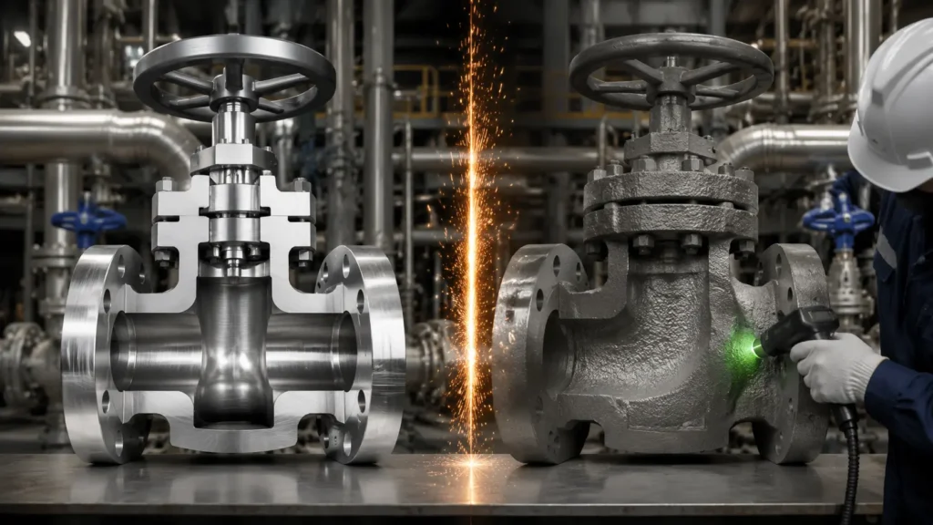
For Class 1500 and Class 2500 valves, forged bodies are usually the practical first choice for small, compact designs. Cast bodies normally become more economical as valve size and internal complexity increase. Class 1500+ does not automatically require 100% radiographic testing of the complete valve body. The decision should be based on valve size, body shape, material, operating temperature, pressure cycles, inspection scope, repair limits, documentation, and delivery risk. A fair comparison requires forged and cast suppliers to quote the same technical requirements. Quick Comparison A forged body starts as solid steel that is heated, shaped, heat treated, and machined. A cast body starts as molten steel poured into a mold. Item Forged body Cast body Best starting point Small, compact, high-pressure valves Large valves with complex passages Internal passage Mainly machined from solid metal Mainly formed by mold cores Main internal concerns Laps, seams, bursts, inclusions, and centerline indications Shrinkage, gas porosity, inclusions, hot tears, and cold shuts Common internal test Ultrasonic testing, or UT Radiographic testing, or RT Repair welding Less common More common when permitted Machining volume Usually higher Usually lower Large-size cost Can increase sharply Usually lower Main schedule risk Raw-forging availability and long machining time RT rejection, repair, repeat heat treatment, or recasting Forging does not guarantee a defect-free body. Casting does not automatically mean low quality. The result depends on the steel source, manufacturing process, heat treatment, inspection, and repair control. Buyers can compare the construction of a forged high-pressure ball valve with a cast steel ball valve, but both quotations must use the same material, design standard, NDE, testing, and documentation requirements. What Class 1500+ Means Class 1500 does not mean that a valve can always operate at exactly 1,500 psi. The class number is a pressure-rating group. Actual allowable pressure depends on body material and operating temperature. A complete valve request should state: Design pressure Design temperature Valve size and type Body material Fluid and service condition Pressure class End connection Applicable valve standard Standard Class or Special Class construction ASME B16.34 covers pressure-temperature ratings, materials, dimensions, nondestructive examination, testing, and marking for cast, forged, and fabricated valves. The purchase order should name the edition that applies to the project.[1] For pipeline ball valves, the RFQ should also define the applicable API 6D valve specifications, including bore, body design, pressure class, material, end connection, seat arrangement, and testing. Standard Class vs Special Class Pressure class and construction category are separate items. A valve may be Class 1500 Standard Class or Class 1500 Special Class. Special Class is not simply a Standard Class valve with an extra RT or UT report. It is a separate rating route under ASME B16.34. The manufacturer must meet all applicable material, manufacturing, examination, testing, and marking requirements in the specified edition. The datasheet should clearly state one of the following: Class 1500 Standard Class Class 1500 Special Class Class 2500 Standard Class Class 2500 Special Class A supplier should not mark a valve as Special Class only because additional NDE was performed. Common Body Materials Service Forged material examples Cast material examples Carbon steel ASTM A105 ASTM A216 WCB or WCC Low-temperature service ASTM A350 LF2 ASTM A352 LCB or LCC Alloy steel ASTM A182 F11, F22, or F91 ASTM A217 grades selected for the service Austenitic stainless steel ASTM A182 F304 or F316 ASTM A351 CF8M or CF3M Duplex stainless steel ASTM A182 F51, F53, or F55 ASTM A995 pressure-containing casting grades ASTM A105 covers forged carbon steel piping components, including valves, for ambient and higher-temperature pressure service. Extra examinations do not apply automatically unless they are required by the product standard or specified in the order.[2] ASTM A350 covers carbon and low-alloy steel forgings intended mainly for low-temperature service and requiring notch-toughness testing.[3] ASTM A182 covers forged or rolled alloy and stainless steel flanges, fittings, valves, and valve parts for pressure and high-temperature service.[4] ASTM A216 covers carbon steel castings for valves and other pressure-containing parts. It includes WCA, WCB, and WCC grades.[5] ASTM A352 covers ferritic and martensitic steel castings for valves and other pressure-containing parts intended mainly for low-temperature service.[6] ASTM A703 provides common requirements for pressure-containing steel castings. The individual material specification still controls the grade-specific chemistry, heat treatment, mechanical properties, and testing.[7] The material grade alone is not enough. The buyer should also check: Heat-treatment condition Chemical composition Tensile and yield results Impact-test temperature and absorbed energy Hardness Positive material identification Heat-number traceability Repair-weld records Final NDE reports For further comparison, see this guide to carbon steel, stainless steel, and duplex ball valve materials. Forging Defects Indication How it forms Useful inspection Lap A surface layer folds over without fully bonding MT or PT after machining Seam A billet defect becomes stretched during forging MT, PT, or UT Burst Internal cracking caused by poor temperature or excessive deformation UT Inclusion Nonmetallic material remains from steelmaking UT Centerline indication Segregation, shrinkage, or inclusions remain near the billet center UT Adequate forging reduction can improve the steel structure and may close some internal voids. It does not remove every inclusion, crack, or segregation zone. UT is still needed when required by the standard or purchase order. The supplier should identify the starting material, forging route, heat treatment, and UT stage. This article on how forged ball valves are made explains the main manufacturing steps. Bar Stock Bodies A body machined from bar stock is not the same as a shaped forging. However, bar stock is not automatically unacceptable. Its suitability depends on: The applicable valve and material standards Body size Location of the bar centerline in the finished body Steelmaking and reduction history UT access and coverage Purchaser restrictions The purchase order should state whether bar stock is allowed, limited to certain sizes, subject to extra UT, or prohibited for pressure-containing bodies. Casting Defects Indication How it forms Main concern Shrinkage A solidifying section does not receive enough liquid metal Internal cavities or connected networks Gas porosity Gas becomes trapped during solidification
Split Body vs Welded Body Ball Valve for Natural Gas Transmission | Pressure Integrity and Repair Comparison
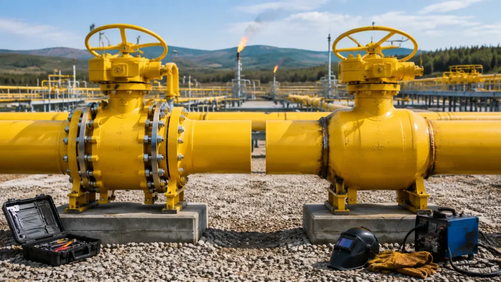
Answer: A fully welded body normally has fewer external leak paths because it removes the large bolted body joint. A split body is easier to overhaul because technicians can open the body and replace the seats, ball, bearings and seals after the valve is safely isolated and removed from service. Fully welded valves are often preferred for directly buried gas pipelines. Split body valves are often more practical at accessible stations where internal repairs are expected. Both designs can handle high-pressure natural gas. ISO 14313:2025 covers pipeline valves in ASME Classes 150, 300, 600, 900, 1500 and 2500, so body style alone does not decide the pressure class.[1] The correct choice depends on the installation, seat design, gas condition, pipe loads, repair plan, permitted shutdown and spare-valve availability. This article mainly applies to large trunnion-mounted ball valves used in natural gas transmission. API Specification 6D defines manufacturing requirements for pipeline and piping valves.[2] API currently lists Addendum 3, issued in March 2025, for API 6D 25th Edition.[3] Pressure Class Range Split body and fully welded valves can both be supplied across common pipeline pressure classes. The exact size and pressure limits depend on the manufacturer’s qualified design, materials and testing. ASME Class Split Body Fully Welded Body Main Selection Factors 150 Commonly available Available Installation access, cost and maintenance plan 300 Commonly available Available Valve size, end connection and seat design 600 Common in transmission service Common in transmission service Pressure integrity, pipe loads and outage plan 900 Design-dependent Design-dependent Body material, wall thickness, torque and testing 1500 Design-dependent Design-dependent Detailed design review and manufacturer qualification 2500 Specialized designs Specialized designs Materials, welds, seats, actuator torque and project approval Do not convert an ASME Class directly into one fixed working pressure. The allowable pressure also depends on body material and design temperature. ASME B16.34 covers pressure-temperature ratings, materials, dimensions, examination, testing and marking for new flanged, threaded, welding-end and certain flangeless valves.[4] Body Construction A split body valve has two or more main pressure-containing body sections. Studs or bolts hold the sections together. An O-ring, gasket or another static seal prevents gas from escaping through each body joint. A fully welded valve joins its main body sections with permanent factory welds. The body cannot be opened by removing studs. Representative Body Design Typical Bolted Main Body Joints Permanent Main Body Welds Two-piece split body 1 Usually none at the main split Three-piece split body 2 Usually none at the main splits Fully welded body 0 One or more, depending on body design The joint count above is representative. The actual number depends on the manufacturer’s construction. It also does not include stem seals, vents, drains, sealant fittings, pipeline flanges or field girth welds. Body construction and pipeline end connection are different features: A split body valve can have flanged or butt-weld ends. A fully welded valve can also have flanged or butt-weld ends. A split body valve with butt-weld ends may still need to be cut out before overhaul. Butt-weld ends reduce the repair advantage of a split body, but they do not require a fully welded body. See the detailed comparison of flanged and welded-end ball valves for the installation and maintenance differences. Body entry type is also a separate choice. A side-entry valve is opened from the side or main split line. A top-entry valve is opened through a top cover. A top-entry design may allow technicians to remove internal parts without cutting the main valve body from the pipeline, but the line must still be isolated, depressurized, drained and made safe. The practical differences are explained in this side-entry versus top-entry ball valve guide. Manufacturing method must also be checked separately: A split body can use cast or forged body sections. A fully welded body can use forged, formed or fabricated sections. A forged valve is not automatically fully welded. A split body valve is not automatically cast. When comparing quotations, keep the pressure class, bore, material, end connection, seat type, examination level and actuator package the same. Otherwise, the price difference may come from several design changes rather than the body construction. Pressure Integrity Valve integrity has three separate parts: Integrity Type What It Means Typical Failure Pressure containment The body, stem seals, fittings and connections keep gas inside the valve. Gas leaks from a joint, stem, fitting or weld. Isolation The closed seats stop gas from passing through the valve. The body remains sound, but gas passes through a damaged seat. Operation The valve reaches its required position under actual line pressure. The actuator moves, but the ball does not fully close. A fully welded body mainly changes pressure containment. It removes the large mechanically sealed main body joint. It does not remove the stem, seats, actuator, vents, drains or pipeline connections. A valve can therefore have a sound welded body and still leak through a damaged seat. It can also isolate the line correctly while releasing gas from a stem seal or drain fitting. Fully Welded Body The main benefit of a fully welded body is the removal of the large bolted body joint. In a split body valve, line pressure creates a force that tries to separate the body sections. The studs must keep enough compression on the joint seal to prevent external leakage. In a fully welded valve, the factory body weld carries this load as part of the pressure shell. There is no removable main body gasket or main body-joint bolt preload. This design is useful for direct burial because: The buried body has fewer large mechanical joints. There are no exposed main body-joint studs. The external body is usually compact. A continuous coating is easier to apply around the main body. There are fewer joint crevices where water and soil can collect. A fully welded valve is not maintenance-free. It still contains stem seals, seats, bearings, vents, drains and sealant fittings. The valve may also contain two different weld categories: Factory body welds: join the main body sections during
