
How to Check Whether a Full-Bore Ball Valve Is Truly Piggable | Bore ID, Pipe Schedule, Transition Geometry
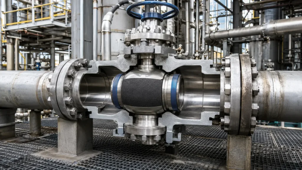
Short answer: A full-bore ball valve is truly piggable only when the exact pig can pass through the finished valve, seats, connections, and adjoining pipe. Check the smallest finished bore, pipe Schedule, internal steps, welds, gaskets, transition length, and actual ball position. The words “full bore” alone are not proof.API 6D covers the design, manufacture, materials, assembly, testing, marking, and documentation of pipeline valves. It does not confirm that one valve can pass every cleaning pig or in-line inspection tool.[1] API has also issued Addendum 3 for the 25th edition, so the purchase specification should state the applicable edition, addenda, and errata.[2] For a basic comparison of full-bore and reduced-bore designs, see this full-bore ball valve guide. Know the Basic Terms NPS and DN are nominal size names. They are not exact inside diameters. OD is the pipe outside diameter. ID is the inside diameter available to the pig. Pipe Schedule identifies a standard wall-thickness series. For the same NPS, a thicker wall normally gives a smaller ID. Full bore describes the valve-port design. It does not prove that the valve bore matches the actual pipe ID. Offset, also called hi-lo at a welded joint, means that the pipe and valve bores do not share the same centerline. Clock position describes where a feature sits around the bore. Twelve o’clock is the top, six o’clock is the bottom, and three and nine o’clock are the sides. Start With the Pig Identify the exact pig before checking the valve. A foam pig, cup pig, disc pig, gauging pig, geometry tool, and intelligent inspection tool can have very different limits. Ask the pig supplier for: Maximum rigid outside diameter Minimum permitted clear bore Maximum inward step Maximum joint offset Maximum restriction length Minimum bend radius Permitted speed range Required pressure difference Bidirectional capability Do not rely on a statement such as “the pig can pass a 10% restriction.” Ask what the percentage is based on: Tool outside diameter Nominal pipe ID Measured pipe ID Diameter reduction Cross-sectional area reduction Also ask how long the restriction may continue. A 5 mm-long seat edge does not affect a pig in the same way as a 500 mm-long reduced bore. API Standard 1163 covers the qualification, selection, reporting, verification, validation, and use of in-line inspection systems. It does not provide one universal valve-bore or step limit for every inspection tool.[3] Check three separate questions: Can it pass? The tool must not become stuck or damaged. Can it keep moving? The line must provide enough pressure difference to overcome friction and restrictions. Can it inspect correctly? Sensors, wheels, magnets, or ultrasonic probes must remain in a usable position. A tool can pass through a valve but still produce poor data if it moves too fast, loses wall contact, or becomes unstable inside the body cavity. Compare Pig and Bore Size Use the smallest opening in the complete installed path: Available Bore ≥ Pig Supplier’s Minimum Bore The smallest opening may be at the: Pipe Valve end Seat ring Seat retainer Ball port Weld root Flange gasket Internal lining Suppose the smallest finished valve opening is 197.6 mm and the pig requires 193.0 mm: Diametral Margin = 197.6 – 193.0 = 4.6 mm If the pig and bore are perfectly centered: Radial Margin = 4.6 ÷ 2 = 2.3 mm per side The 4.6 mm value is the total diameter difference. It does not mean there is 4.6 mm of space on each side. For rigid circular tool modules, the minimum clear circle controls passage. Flexible foam, cups, and discs may deform through a smaller or oval opening, but the rigid shaft, body, magnets, electronics, or wheels must still fit. Check the Pipe Schedule For plain, unlined pipe: Pipe ID = OD – 2 × Wall Thickness ASME B36.10 standardizes dimensions for welded and seamless wrought steel pipe.[4] ASME B36.19 covers welded and seamless wrought stainless steel pipe.[5] The following rounded nominal values show how much Schedule can change the bore: Pipe Size Schedule 40 ID Schedule 80 ID ID Difference NPS 4 About 102.3 mm About 97.2 mm About 5.1 mm NPS 6 About 154.1 mm About 146.4 mm About 7.7 mm NPS 8 About 202.7 mm About 193.7 mm About 9.0 mm NPS 12 About 303.3 mm About 288.9 mm About 14.4 mm An NPS 8 valve with a 198.0 mm finished bore creates different conditions depending on the adjoining pipe: Schedule 40 pipe ID is about 202.7 mm, so the valve creates a reduction. Schedule 60 pipe ID is about 198.5 mm, so the difference is small. Schedule 80 pipe ID is about 193.7 mm, so the valve bore is larger than the pipe bore. The NPS 8 Schedule 40-to-valve change is: Diameter Reduction = 202.7 – 198.0 = 4.7 mm Radial Step = 4.7 ÷ 2 = 2.35 mm The diameter decreases by about 2.3%, but the flow area decreases by about 4.6%: Area Reduction = 1 – (198.0 ÷ 202.7)2 ≈ 4.6% Area reduction helps explain the change in flow path, but it does not replace the pig supplier’s mechanical passage limits. Record the pipe data separately on both sides of the valve: Item Upstream Downstream Pipe OD Schedule or specified wall Measured wall Calculated nominal ID Measured end ID Lining thickness Internal seam height Ovality Do not assume that both sides are identical. A mainline valve may connect standard-wall pipe to a heavy-wall station spool, launcher connection, forged pup, or replacement section. Include Linings and Deposits For a uniformly lined pipe: Finished ID = OD – 2 × Wall Thickness – 2 × Lining Thickness A lining occupies space on both sides of the diameter: Lining Thickness per Side Total Bore Reduction 0.5 mm 1.0 mm 1.0 mm 2.0 mm 1.5 mm 3.0 mm 3.0 mm 6.0 mm For example, a 500 mm machined valve bore with a uniform 1.5 mm overlay becomes: Finished ID = 500 – 2 × 1.5 = 497 mm If the pig requires a 499
How to Select Ball Valve Pressure Class at Elevated Temperature | ASME B16.34 Derating, Design Conditions
Select the ball valve pressure class by checking every real design pressure and metal-temperature pair against the correct ASME B16.34 material table. After the shell rating passes, confirm that the seat, packing, body seals, maximum differential pressure, body cavity, flange joint, and actuator also pass. Class 150 does not mean 150 psi, and Class 300 does not mean 300 psi. The class number identifies a pressure-rating group. The allowable working pressure changes with material and temperature. ASME B16.34 covers pressure-temperature ratings, materials, dimensions, tolerances, examination, testing, and marking for covered flanged, threaded, welding-end, wafer, and flangeless valves.[1] A correct selection needs three separate checks: Shell rating: Can the body, closure, and other pressure-containing parts hold the internal pressure at the design metal temperature? Seat rating: Can the seats seal against the maximum pressure difference across the closed valve? Complete-valve rating: Can the packing, body seals, stem, bolting, end connections, and actuator work under the same conditions? A valve may pass the ASME B16.34 shell check but still be unsuitable because its seat, seal, or actuator limit is lower. Know the Units Use one pressure unit and one temperature unit throughout the calculation. Do not mix gauge pressure with absolute pressure. Value Equivalent 1 MPa 10 bar 1 bar 100 kPa 1 bar About 14.504 psi 10 bar About 145 psi 300°C 572°F 400°C 752°F NIST lists 1 psi as 6,894.757 Pa, which gives approximately 14.504 psi per bar.[2] Common pressure labels include: bar(g) or psig: Pressure above local atmospheric pressure bar(a) or psia: Pressure measured from absolute vacuum Differential pressure: Pressure difference between the two sides of the closed valve For example, 10 bar(a) is not the same as 10 bar(g). Near normal atmospheric pressure, 10 bar(a) is approximately 9 bar(g). Set the Design Conditions Do not select Class 150, 300, or 600 from normal operating pressure alone. List every pressure and metal-temperature combination the valve may experience. ASME B31.3 contains requirements for process piping used in refineries, chemical plants, hydrogen facilities, pharmaceutical plants, semiconductor plants, cryogenic plants, and related processing facilities.[3] Condition Pressure to Check Temperature to Check Normal operation Normal line pressure Normal valve-body temperature Maximum operation Highest operating pressure Temperature at that pressure Startup Maximum startup pressure Startup metal temperature Shutdown Trapped or equalized pressure Shutdown metal temperature Pump shutoff Suction pressure plus shutoff head Fluid temperature at shutoff Compressor settle-out Equalized system pressure Settle-out temperature Blocked outlet Maximum upstream pressure Temperature during blockage Steam-out Steam supply pressure Steam-out metal temperature Regeneration Regeneration pressure Regeneration temperature Heat tracing Pressure in trapped fluid Maximum traced metal temperature Relief event Required relief-case pressure Temperature during relief Minimum temperature Pressure during cooling or depressurization Lowest metal temperature For steam applications, also check steam state, tracing temperature, cleaning temperature, seat material, packing, and bolting. See this guide to sizing a ball valve for steam service. Record Time and Frequency Temperature alone does not describe the full service. Record how long the valve stays at each temperature and how often the condition occurs. The following is an example operating profile, not a universal industry requirement: Condition Temperature Duration Example Frequency Normal operation 300°C Continuous 8,000 hours per year Startup 200°C 2 hours 30 times per year Steam-out 400°C 4 hours 6 times per year Cooling 300°C to 50°C 6 hours 30 times per year A seal that survives six four-hour steam-out cycles may not be suitable for continuous operation at 400°C. Thermal cycling can also change gasket compression, seat contact, packing friction, and actuator torque. Keep Conditions Together Pressure and temperature must be checked as pairs that occur at the same time. For example, a line may have: 20 bar(g) at 150°C during startup 12 bar(g) at 350°C during normal operation 6 bar(g) at 420°C during steam cleaning Check these three pairs separately. Do not combine 20 bar(g) with 420°C unless that condition can actually occur. The highest pressure may occur at a temperature where the material still has a high allowable pressure. The highest temperature may occur when the system pressure is low. Neither value automatically controls the class. A useful comparison is: Shell utilization = Design pressure ÷ Allowable pressure at the same temperature The result must not exceed 1.00. The condition with the highest utilization is the controlling shell-rating condition. This ratio is a comparison tool, not an ASME formula. Utilization Meaning 0.50 Design pressure uses 50% of the allowable pressure 0.85 Design pressure uses 85% of the allowable pressure 0.98 The numerical margin is small and input uncertainty needs careful review 1.00 Design pressure equals the allowable pressure Above 1.00 The selected class fails that condition There is no universal rule that every valve must stay below 80% or 90% utilization. Any required extra margin must come from the project specification, owner, or governing design rules. Use Metal Temperature ASME pressure-temperature ratings apply to the pressure-containing metal, not automatically to the bulk fluid temperature. The valve body may be heated or cooled by: Steam tracing Electric tracing Insulation Sunlight Radiant heat from nearby equipment Stagnant fluid Thermal stratification Heat transfer from a vessel or furnace Rapid depressurization A closed bypass valve near a hot vessel may become hotter than the flowing main line. A traced valve can remain hot after process flow stops. For example, the process fluid may normally be 280°C while an external tracing system can heat an isolated valve body to 320°C. The pressure-temperature check should use the credible valve-body temperature for that condition. Find the Design Pressure Normal operating pressure is only one input. The valve may see higher pressure during pump shutoff, compressor shutdown, relief, static liquid head, or blocked-in heating. Pressure Source Data Required Normal Source Pump shutoff Suction pressure, shutoff head, fluid density, elevation Approved pump curve Compressor settle-out Connected volumes, initial pressures, temperatures Process calculation Static liquid head Fluid density and elevation difference Equipment layout Relief event Set pressure, permitted accumulation, backpressure Relief calculation Utility connection Maximum utility supply pressure Utility specification Blocked-in heating Trapped volume, fluid, heating range,
How to Verify Ball Valve Wall Thickness and Corrosion Allowance | Drawing Review, Material Loss, Design Margin
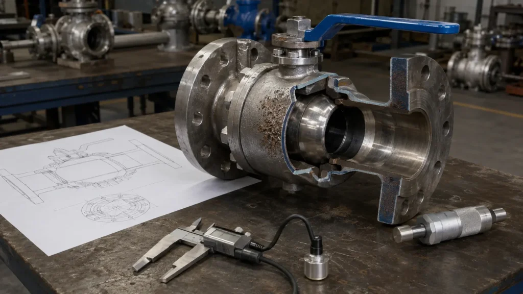
To verify ball valve wall thickness, calculate the minimum required wall at each critical location, include the specified corrosion allowance, account for manufacturing tolerances and machining, and compare the result with the lowest confirmed measurement at the same location. For an in-service valve, use current thickness, historical readings, damage shape and an approved retirement thickness to decide whether the valve can remain in service. ASME B16.34 covers pressure-temperature ratings, materials, dimensions, tolerances, examination, testing and marking for new cast, forged and fabricated valves.[1] API Specification 6D may also apply to ball valves used in petroleum and natural-gas pipeline or piping systems.[2] For valves installed in process piping, ASME B31.3 may control the connected piping system, including its materials, components, design, fabrication, examination, inspection and testing.[3] In-service valves within an API 570 piping circuit should be inspected under the applicable API 570 and API RP 574 requirements.[4] Set the Design Basis Do not start by comparing an ultrasonic reading with a value taken from an uncontrolled table. First confirm the exact valve and service conditions. Information What to confirm Why it matters Valve size NPS or DN Changes body dimensions and internal geometry Pressure class Class 150, 300, 600, 900, 1500 or 2500 Identifies the pressure-temperature rating group Design pressure Maximum specified design pressure Controls the required pressure capacity Design temperature Maximum and minimum design temperatures Changes material rating and low-temperature requirements Body material Exact material specification, grade and product form Affects rating, corrosion resistance and inspection response Body design Cast, forged, fabricated or fully welded Changes tolerances, machining and possible thin areas Ball support Floating or trunnion-mounted Changes the critical bores and pressure-boundary sections Port design Full bore or reduced bore Changes the ball port, body cavity and seat-pocket dimensions Corrosion allowance Internal, external, both or none Defines the additional sacrificial metal Standard edition Edition stated in the purchase contract Prevents requirements from different editions being mixed A pressure class is not one fixed pressure. The allowable pressure changes with material and temperature. Use the material, design temperature and design pressure to confirm that the selected class is suitable. Then determine the wall requirement for each pressure-containing location. The valve structure also changes the review. A forged floating ball valve normally requires close checks behind both seats and around the stem bore. A forged trunnion-mounted ball valve also has upper and lower trunnion bores, bearing pockets, drain passages and seat-injection passages. If essential records are missing: Do not assume a standard corrosion allowance such as 3 mm. Do not automatically use the newest standard edition. Do not use a catalogue image as the manufacturing drawing. Do not treat nominal drawing thickness as an original measurement. Do not calculate corrosion rate from readings taken at different positions. Define the Thickness Values A ball valve can have different requirements at the seat pocket, stem bore, drain passage and end connector. Each value should therefore be linked to a specific location. The letter i below represents one defined location. Symbol Meaning tstandard,i Approved pressure-design minimum at location i CAi Corrosion allowance that applies at location i trequired,i Required finished wall at location i tdrawing,i Nominal wall shown on the drawing tfinished-min,i Lowest wall allowed after tolerances and machining tactual,i Lowest valid measured wall at the same location tretirement,i Approved in-service retirement thickness When the project requires corrosion allowance to be added outside the pressure-design minimum: trequired,i = tstandard,i + CAi This formula applies only when the purchase specification clearly requires the allowance as additional metal. Confirm that it applies to the component and surface being reviewed and that it has not already been included in the manufacturer’s minimum wall. Example: Pressure-design minimum: 18.0 mm Specified corrosion allowance: 3.0 mm Required finished wall: 21.0 mm A finished wall of 20.6 mm remains 2.6 mm above the pressure minimum, but it is 0.4 mm below the full project requirement. Corrosion allowance is useful for predictable wall loss. It should not be treated as protection against stress-corrosion cracking, hydrogen damage, fatigue, deep pitting or severe cavitation. For H2S-containing oil and gas production and natural-gas sweetening environments within its scope, ISO 15156 covers the selection of cracking-resistant metallic materials.[5] Review the Drawing Use the approved sectional manufacturing drawing. Confirm its number, revision, valve model, size, class, material, bore type and purchase-order item. Mark every pressure-containing part: Main body End connector or closure Stem housing Lower trunnion housing Drain, vent and injection bosses Body joints and pressure-containing welds Flanged, threaded or butt-welded ends Then locate the shortest metal path between the pressure surface and the outside surface. The main centerline section is rarely enough. Critical sections normally include: Behind the upstream and downstream seat pockets Around the stem bore Around the lower trunnion bore Between the body cavity and drain passage Between the body cavity and vent passage Below sealant-injection passages Between seal grooves and the pressure cavity Near bolt holes close to the cavity At end-piece necks and weld-end transitions At repaired or ground areas An angled drain or injection hole can create a diagonal minimum ligament that does not appear on the main section. Normal-beam ultrasonic testing measures along the sound path and may not find the shortest diagonal distance. Use controlled drawing geometry, coordinate measurement, radiography, computed tomography or another qualified method when required. For threaded ports, check the largest material-removal diameter created by the internal thread root, counterbore, thread relief, entry chamfer and tapered profile. The nominal opening alone may overstate the remaining metal. The body cavity may also be larger than the ball port. A full-bore valve should not be reviewed only from the pipeline bore. Check the flow port, ball cavity and seat-pocket diameter separately. The main structural differences are also discussed in this high-pressure API 6D forged ball valve overview. Check the Drawing Margin Convert nominal drawing dimensions into the lowest permitted finished wall. tfinished-min,i = tdrawing,i − permitted negative tolerance − additional machining This is a simplified one-dimensional calculation. Core shift, forging eccentricity and forming reduction may need separate
Ball Valve Is Fully Closed but Flow Continues—Is It Seat Damage or an Actuator Travel Error
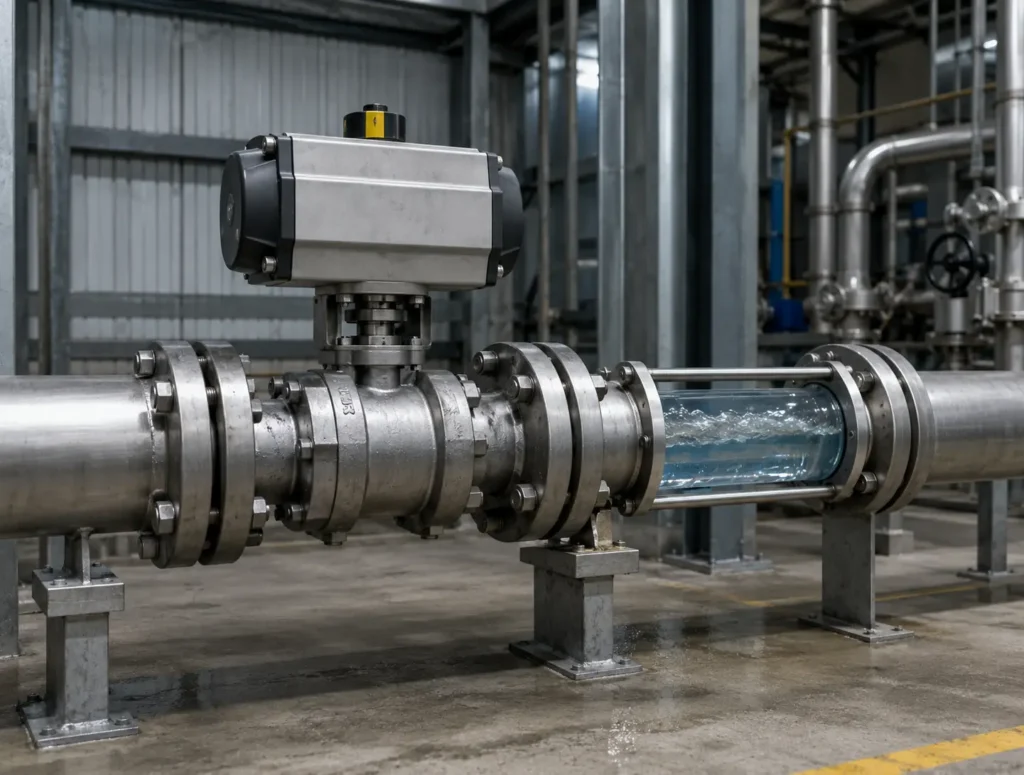
Short answer: first confirm that fluid is really passing through the valve. Then check whether the valve stem and ball reached the correct closed position. If the ball stops early, inspect the actuator travel, stop settings, coupling, energy supply, and valve torque. If the ball reaches the correct position but measured leakage remains, inspect the seats, ball, seat springs, rear seals, and pressure direction. A control-system Closed signal only shows that a switch or position sensor has changed state. It does not prove that the ball is fully seated. Actuator travel error and seat damage can also happen together. A ball that stops slightly early leaves a narrow opening that can erode the seat. A swollen, dirty, or damaged seat can also raise torque and prevent the actuator from completing its travel. About the data in this article: numerical examples such as pressure, time, current, angle, and leakage rate show how field records can be interpreted. They are not universal acceptance limits. The correct limit must come from the valve datasheet, actuator manual, project specification, and applicable test standard. Safety: do not loosen the actuator, coupling, packing, body bolts, drain plug, vent plug, or pipe connection while pressure or stored actuator energy may remain. Isolate every energy source, lock it out, depressurize the system, control spring energy, drain or purge the fluid, and verify isolation before work starts. OSHA requires stored or residual energy to be relieved, disconnected, restrained, or otherwise made safe before servicing.[1] Fast Diagnosis Finding Most useful next check Downstream pressure stays stable Trapped pressure, temperature change, or instrument response Downstream pressure continues rising Seat leakage, bypass flow, reverse flow, or another open connection A small approved travel correction reduces leakage Limit switch, stop setting, coupling, calibration, debris, or worn seat The valve closes without pressure but stops early under pressure Insufficient actuator output or excessive valve torque The actuator moves farther than the valve stem Coupling slip, worn adaptor, damaged key, spline, or internal drive The stem reaches the correct position but leakage remains Seat, ball, seat spring, rear seal, or seat-loading problem Leakage changes when pressure direction is reversed Directional seat design or damage to one seat The problem started after welding, flushing, or startup Rust, weld slag, scale, sand, or construction debris These findings are clues, not final proof. Do not increase actuator torque simply to force the valve closed. Extra torque may reduce leakage for a short time while cutting a soft seat, twisting the stem, damaging the coupling, or chipping a hard coating. Confirm the Leak Before removing the valve, identify what type of leakage is present: Through-seat leakage: fluid passes between the ball and seat into the opposite side of the pipeline. External leakage: fluid escapes through the stem packing, body joint, flange, vent, drain, or pressure-containing wall. Cavity discharge: fluid already trapped inside the valve body leaves through a drain or bleed connection. Cross-flow: fluid reaches the downstream pipe through a bypass, check valve, common header, or connected machine. ISO 15848-1 covers external leakage from valve stem seals and body joints. It does not set the through-seat leakage limit for a closed ball valve.[2] For external and internal leakage differences, see how to troubleshoot a leaking ball valve in the field. Record upstream pressure, downstream pressure, fluid temperature, valve position, pump status, and time after closure. One pressure reading is not enough. Stable downstream pressure: pressure may simply be trapped. Pressure rising toward upstream pressure: new fluid is entering the downstream section. Pressure rising with temperature: trapped liquid may be expanding. Pressure changing when another valve moves: a bypass, common header, or connected unit may be involved. Illustrative pressure trend: Time After Closure Upstream Pressure Downstream Pressure Fluid Temperature 0 minutes 10.0 bar 0.3 bar 24°C 5 minutes 10.0 bar 0.9 bar 24°C 15 minutes 9.9 bar 2.1 bar 25°C 30 minutes 9.9 bar 3.4 bar 25°C This example shows that fluid is entering the downstream section. It does not show the exact leakage rate because the downstream volume, fluid compressibility, pipe expansion, and connected equipment are not known. Do not judge leakage size only from the speed of pressure rise. The same leak can produce a fast pressure rise in a small closed volume and a slow rise in a large pipe or vessel. Walk the actual piping and check manual bypasses, automatic recirculation lines, check valves, warm-up lines, drains, vents, instrument tubing, flushing lines, temporary hoses, parallel equipment, and three-way valves. Change one condition at a time. If closing another valve stops the flow, another path is involved, but the original valve may still require a separate seat test. Also check the flowmeter. Zero offset, electrical noise, vibration, gas bubbles, a partly filled pipe, density compensation, blocked impulse lines, or operation below the meter’s reliable range can create a false low-flow reading. Compare the signal with downstream pressure, tank level, collected liquid, pipe temperature, or another calibrated instrument. Identify the Valve Record the valve model, size, pressure class, seat material, pressure direction, actuator model, and fail action before testing. The diagnosis changes with the valve design. Floating ball: pressure moves the ball slightly toward the downstream seat. Many soft-seat designs also use initial seat preload for low-pressure sealing. Trunnion-mounted ball: upper and lower supports hold the ball while movable seat rings press against it. Soft seat: provides tight shutoff but can be cut, extruded, swollen, softened, or permanently deformed. Metal seat: suits many hot or abrasive services but can suffer scoring, galling, coating loss, corrosion, or erosion. Control ball valve: may have a specified allowable shutoff class rather than an isolation-valve zero-leakage requirement. A typical soft-seated trunnion ball valve may use self-relieving SPE seats, DPE seats, or a mixed arrangement. These configurations do not react to cavity and line pressure in the same way. ISO 14313:2025 covers the design, manufacture, materials, assembly, testing, documentation, and process control of covered pipeline valves. It supplements API 6D, 25th edition, for its stated scope.[3] The actual seat action must still
Ball Valve Stem Leakage After Thermal Cycling | Packing Relaxation, Live Loading, Repair Steps
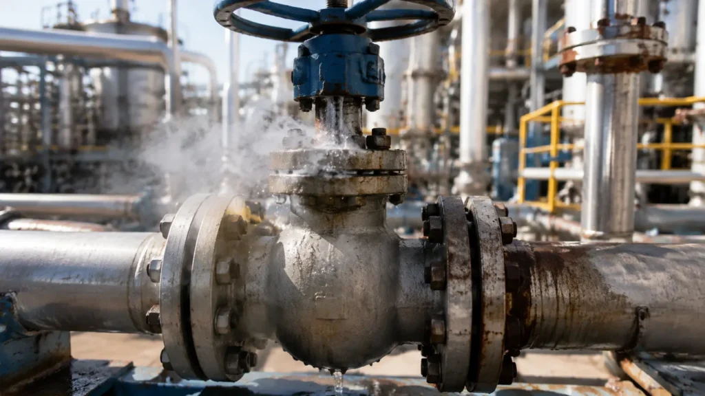
Ball valve stem leakage after thermal cycling is usually caused by a loss of packing pressure. Heating and cooling can make the packing settle, creep, wear, or remain permanently compressed. A small, stable leak may allow one controlled gland adjustment. If the leak returns after one or two complete thermal cycles, the valve becomes harder to operate, or the live-loading springs have no travel left, stop tightening and inspect the complete packing system.Before repair, confirm the exact leak point and record the valve temperature, pressure, position, spring-stack height, operating torque, and adjustment history. Gland torque, packing order, spring height, test pressure, and acceptable leakage are specific to the valve model and must come from the manufacturer. Confirm the source: Make sure the fluid is coming from the stem, not a body joint, vent, drain, flange, or nearby tube. Adjust only when permitted: Tighten the gland in small, equal steps and stop at the approved setting. Repair recurring leaks: If leakage returns after thermal cycling, replace the packing and inspect the stem, springs, actuator alignment, and piping load. How the Stem Seal Works The valve stem connects the ball to the handle, gearbox, or actuator. Because the stem must rotate, it passes through an opening in the valve body. Packing is compressed around the stem to prevent process fluid from escaping through this opening. A typical stem-sealing system contains: PTFE, graphite, or composite packing rings A packing follower A gland plate Gland studs and nuts Washers or Belleville springs Anti-extrusion rings O-rings or secondary seals A graphite fire-safe backup seal in some designs The nuts or springs push the gland plate downward. The gland plate pushes the follower, and the follower compresses the packing. The packing then presses inward against the stem and outward against the packing-chamber wall. If packing pressure is too low, fluid can travel along the stem. If it is too high, stem friction rises and the actuator may not complete the full valve stroke. The stem seal must not be confused with the stem-retention system. Many ball valves use an internal shoulder or anti-blowout stem design. A nut that holds the stem in place is not always a packing-adjustment nut. The internal arrangement also differs between floating and trunnion-mounted valves. This guide to trunnion-mounted ball valve selection explains the main construction and application differences. API 6D specifies requirements for pipeline valves, including ball valves, but the exact stem, seat, cavity, and packing arrangement still depends on the valve design and manufacturer drawing.[1] Why Thermal Cycling Causes Leakage Thermal cycling means that the valve repeatedly heats up and cools down. It is common in steam systems, thermal-oil lines, batch plants, regeneration units, reactors, and equipment that starts and stops often. The stem, body, packing, gland studs, springs, actuator bracket, and piping may use different materials. They also heat and cool at different speeds. During heating: The stem and valve body expand. Soft packing becomes easier to deform. PTFE packing may creep more quickly. Stud and spring load may change. Trapped liquid may expand and increase cavity pressure. Hot piping may push or pull on the valve body. During cooling: The metal parts contract. The packing may not return to its original height. The gland load may fall. A small low-pressure area may open beside the stem. A leak that was hidden while hot may appear. The common failure path is: Heating changes component size and packing load → the packing becomes thinner or permanently deformed → the valve cools → the packing does not fully recover → sealing pressure falls → fluid leaks along the stem. The change can build slowly. One thermal cycle may cause no visible leakage, while repeated cycles gradually reduce the remaining packing load. Temperature, Pressure, and Pipe Load Temperature changes packing stiffness, friction, strength, and recovery. PTFE usually provides low friction and broad chemical resistance, but it can creep under sustained load. Graphite generally handles higher temperatures, but it may create more stem friction and can deteriorate in hot oxidizing service. The packing temperature may be different from the process-fluid temperature. Insulation, heat tracing, bonnet length, airflow, nearby equipment, and cycle duration can all change the temperature around the stem seal. For steam service, pressure, temperature, seat material, packing, and thermal derating should be checked together. The main limits are explained in this steam ball valve sizing guide. Pressure provides the force that pushes fluid through a leakage path. A scratch or small gap that remains dry at low pressure may leak quickly when pressure rises. A closed ball valve can also trap liquid inside its body cavity. If that liquid heats up and has no safe relief path, cavity pressure may increase. Closing the valve therefore does not prove that the stem area is safe to dismantle. Hot piping can place bending or twisting force on the valve. Poor supports, flange misalignment, actuator weight, and limited pipe flexibility can move the stem sideways inside the packing. ASME B16.34 covers pressure-temperature ratings, materials, dimensions, examination, testing, and marking for many industrial valves. It does not replace a piping-stress review or correct field installation.[2] Four Packing Failure Modes Failure Mode What Happens Typical Evidence Creep The packing slowly changes shape under load and becomes thinner. The leak returns after hot service, the follower moves downward, or soft packing is pushed into a clearance. Consolidation New packing rings settle more tightly together during the first cycles. Leakage begins soon after repacking and may stop after one correct readjustment. Compression set The packing remains permanently flattened and has little spring-back. The valve seals while hot but leaks after cooling; removed rings remain flat. Wear Stem movement removes packing material and opens a leakage path. Leakage starts after valve operation, packing is worn on one side, or the stem has a polished wear band. These failure modes often occur together. Hot PTFE may creep first. The reduced load then allows slight stem movement, which increases wear and makes an existing scratch more likely to leak. Use
Ball Valve Leaks Only in One Flow Direction—What Does It Mean? | Seat Orientation, SPE/DPE, Damage Check
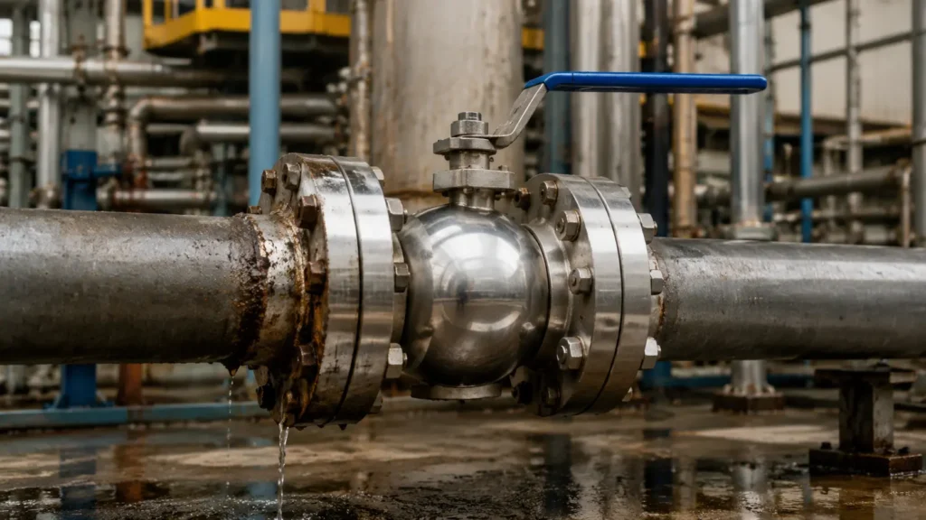
A ball valve that seals from one side but leaks when pressure is reversed may be directional by design, installed backward, fitted with an SPE/DPE seat arrangement, not fully closed, tested incorrectly, or damaged on one sealing side. Start by confirming which side is pressurized, what the body arrow means, and whether the valve is floating-ball or trunnion-mounted. Do not reverse, repair, or replace the valve before checking its drawing, seat arrangement, cavity pressure, and actual closed position. Find the Leak Path A falling pressure reading does not prove that fluid has passed through the complete valve. First identify where the fluid is going. Through-seat leakage means fluid passes from the pressurized pipeline side, through the closed ball-and-seat system, and reaches the opposite pipeline side. Common leak paths include: A gap between the ball and seat A scratch across the ball sealing track Debris trapped on the seat A cut or deformed soft-seat insert Leakage behind the movable seat ring A damaged O-ring, lip seal, or backup ring An internal relief hole facing the wrong side Cavity bleed flow means fluid passes the first seat, enters the body cavity, and leaves through the drain or vent. This confirms that the first seat is passing, but it does not prove that fluid has crossed the second seat. Cavity relief flow may be normal. An SPE seat can open after cavity pressure rises high enough, releasing trapped pressure toward the lower-pressure line. External leakage means fluid escapes through the stem packing, body joint, flange, weld, drain fitting, vent fitting, or pressure-containing body. ISO 15848-1 covers external leakage from valve stem seals and body joints; it does not set through-seat leakage limits.[1] If fluid is escaping to the atmosphere, stop the test and follow the approved site isolation procedure. Check Pressure Direction The normal flow direction is not always the pressure direction when the valve is closed. For example, normal flow may run from Side A to Side B. During shutdown, backflow, testing, or equipment isolation, Side B may remain pressurized after Side A has been drained. The valve is then loaded in the reverse direction. Use fixed names during testing: Side A: one physical end of the valve Side B: the other physical end Pressure direction: the side supplying pressure during the test Normal flow: the usual process-flow direction An arrow on the valve may show: Normal or preferred flow The required sealing direction The high-pressure end The cavity-relief direction The correct position of an internal relief hole Do not guess what the arrow means. Check the valve drawing, data sheet, installation manual, and factory test report. Before testing, record: Manufacturer, model, and serial number Valve size and pressure class Floating or trunnion-mounted design Seat and secondary-seal materials SPE, DPE, or mixed seat arrangement High-pressure-end marking Actuator model and settings Previous test and repair records The ball valve installation and post-installation testing guide explains why valve orientation, pipe cleanliness, alignment, and actuator setup should be checked before service. Know the Valve Design The meaning of one-direction leakage depends on whether the ball moves toward the seat or the seat moves toward the ball. Floating ball valve: The ball is supported mainly by the seats and stem. When the valve is closed, line pressure pushes the ball slightly toward the downstream seat. That seat normally carries most of the sealing load. Many floating ball valves can seal from either end. Some are directional because they use: A drilled pressure-relief hole Different seats on the two sides One soft seat and one metal seat An uneven seat-support design A V-port or segmented ball A preferred direction for lower torque or less wear If a floating valve leaks only when Side A is pressurized, the pressure may be loading a damaged Side B seat or pushing that seat across a scratched part of the ball. Trunnion-mounted ball valve: The ball is held by trunnions, bearings, or support plates. The seat rings move toward the ball and are normally loaded by springs and fluid pressure. SPE and DPE normally describe these pressure-responsive trunnion seat systems. They should not automatically be used to describe every floating ball valve. For more detail, see the comparison of floating and trunnion-mounted ball valves. Typical floating designs are also shown on the forged soft-seated ball valve page. Understand SPE and DPE Pressure acts on the effective area of a movable seat ring. The basic relationship is: Hydraulic force = pressure difference × effective area. The following values are simple calculations, not valve-design limits: Pressure difference Effective seat area Hydraulic force 10 bar 20 cm² 2,000 N 50 bar 20 cm² 10,000 N 100 bar 20 cm² 20,000 N At the same 50 bar pressure difference, increasing the effective area from 20 cm² to 30 cm² raises the hydraulic force from 10,000 N to 15,000 N. This explains why a small change in seat diameter can noticeably change sealing force and operating torque. A force of 10,000 N is about 1.02 tonne-force. Actual seat load also depends on spring force, seal friction, seat dimensions, body movement, and contact between the ball and seat. SPE means Single Piston Effect. Pressure from the pipeline side normally pushes an SPE seat toward the ball. Pressure from the body-cavity side can push it in the opposite direction. An SPE seat has two main jobs: Seal against pressure from its pipeline side Release excessive cavity pressure toward a lower-pressure line The seat does not necessarily open as soon as cavity pressure starts rising. It may continue sealing until cavity pressure reaches its relief point. A typical sequence is: Side A is pressurized. The Side A seat begins to pass. Pressure enters the body cavity. The opposite SPE seat continues holding. Cavity pressure reaches the relief point. The opposite seat moves away from the ball. Pressure is released into the lower-pressure line. This may produce repeated pressure rise, sudden flow, pressure drop, and resealing. It does not automatically mean that both seats are damaged. DPE means Double
Why Does Pressure Build Up Inside a Closed Ball Valve? | Cavity Pressure, Thermal Expansion, Relief Design
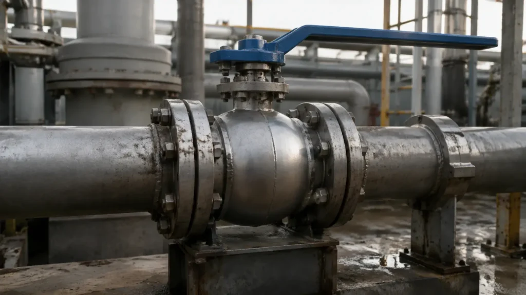
Quick answer: A closed ball valve can trap liquid between its two seats. If the liquid warms, leaks in from a higher-pressure side, or starts to vaporize, pressure inside the valve cavity can rise above both upstream and downstream pressure. The cavity therefore needs a reliable relief path through a self-relieving seat, a vented ball, or a separate relief device.API 6D requires automatic cavity relief when liquid trapping is possible. For covered conditions up to 250°F (121°C), cavity relief pressure must not exceed 33% differential pressure above the valve pressure rating.[1] Where Pressure Is Trapped A ball valve contains a drilled ball between two seats. When the valve closes, the solid sides of the ball block the pipeline openings. Fluid may remain in the space around the outside of the ball, between the two seats. This space is called the body cavity. The cavity may contain: Process liquid Condensate Water left after hydrostatic testing Cleaning or flushing fluid Refrigerant or liquefied gas Oil, grease, or sealant A mixture of liquid and vapor Fluid leaking through one seat A closed valve can therefore contain three different pressures: Upstream pipeline pressure Downstream pipeline pressure Body-cavity pressure These pressures do not have to be equal. For example, a valve may close while both sides are at 50 bar. The downstream pipe is then drained to zero, but the cavity remains close to 50 bar because the seats isolate it from the downstream gauge. If the trapped liquid becomes warmer, cavity pressure may rise above 50 bar. The final trapped pressure also depends on the operating sequence. While the ball is moving, the cavity may briefly connect with one or both sides of the pipeline. Upstream pressure, downstream pressure, seat design, valve direction, and the timing of depressurization can all affect the pressure left inside the cavity. A small cavity does not mean a small risk. Even a few hundred milliliters of completely trapped liquid can generate damaging pressure. Thermal Expansion Heating a trapped liquid is the most common cause of cavity overpressure. Most liquids expand as their temperature rises. In an open tank, the liquid level rises. Inside a sealed valve cavity, there may be almost no free space for the added volume. The liquid can only: Compress slightly Move a seat Compress an O-ring or soft seal Stretch the valve body or connected pipe Leak through a seat Escape through a relief path If none of these movements provides enough space, pressure rises quickly. Common heat sources include: Direct sunlight Steam tracing Electric heat tracing Nearby hot equipment Heat conducted through connected pipe Hot process fluid before isolation Heat remaining after shutdown Cold liquid warming to room temperature External fire The liquid does not need to boil. Ordinary liquid expansion can damage seats, seals, fittings, or the valve body. OSHA has warned that isolated equipment containing liquid can be overpressurized by thermal expansion, causing rupture and loss of containment.[2] One common case occurs when a valve is filled with cold liquid at night and heated by sunlight the next day. Another occurs when production stops but the steam tracing remains on. The liquid continues to absorb heat even though there is no flow. For hot systems, the valve rating must be checked at the actual service temperature rather than at room temperature. This is also important when selecting a ball valve for steam or other high-temperature service. Pressure Rise Data A simple screening equation for a completely liquid-filled, rigid, leak-free cavity is: Pressure rise ≈ bulk modulus × volumetric expansion coefficient × temperature rise The following example uses: Liquid bulk modulus: 1.5 GPa Volumetric expansion coefficient: 0.0007 per °C No gas pocket No seat movement or leakage No expansion of the valve body Temperature Rise Theoretical Pressure Rise Pressure Rise in psi 5°C 5.25 MPa / 52.5 bar About 761 psi 10°C 10.5 MPa / 105 bar About 1,523 psi 20°C 21 MPa / 210 bar About 3,046 psi 30°C 31.5 MPa / 315 bar About 4,569 psi These are theoretical screening values, not predictions for a real valve. Actual pressure may be lower because the valve body stretches, seals compress, seats move, or fluid leaks out. The data still show why a modest temperature rise cannot be ignored. Technical work published through the U.S. Chemical Safety Board also shows that trapped-liquid pressure can become very high while the required thermal relief area remains relatively small.[3] An accidental gas pocket may reduce the initial pressure rise because gas is compressible. It is not a reliable safeguard. The amount of gas is unknown and may disappear after flushing, hydrotesting, condensation, or further seat leakage. Expansion Volume Data Thermal overpressure may require only a small amount of liquid to be released. A simple estimate is: Expansion volume ≈ cavity volume × expansion coefficient × temperature rise The following table uses a volumetric expansion coefficient of 0.0008 per °C and a temperature rise of 30°C. Cavity Volume Added Liquid Volume 0.25 L 6 mL 0.50 L 12 mL 1.00 L 24 mL 2.00 L 48 mL 5.00 L 120 mL A 1 L cavity heated by 30°C may add only about 24 mL of liquid volume. However, if those 24 mL cannot escape, the cavity pressure can rise sharply. This is why thermal relief is often described as a small-flow, high-pressure-risk case. Heating Rate Data The required thermal relief flow depends on how quickly the liquid becomes warmer. A simple estimate is: Expansion flow ≈ cavity volume × expansion coefficient × temperature rise per unit time The following example uses a 1 L liquid-filled cavity and an expansion coefficient of 0.0008 per °C. Heating Rate Added Volume per Hour Average Expansion Flow 2°C/hour 1.6 mL/hour 0.027 mL/min 5°C/hour 4.0 mL/hour 0.067 mL/min 10°C/hour 8.0 mL/hour 0.133 mL/min 20°C/hour 16.0 mL/hour 0.267 mL/min These flows are small, but the relief path can still fail if its inlet is blocked, its outlet has excessive backpressure, or the fluid freezes, crystallizes, or polymerizes inside a narrow passage.
How Much Actuator Safety Factor Does a Ball Valve Need? | Normal, Emergency, Low-Temperature Service
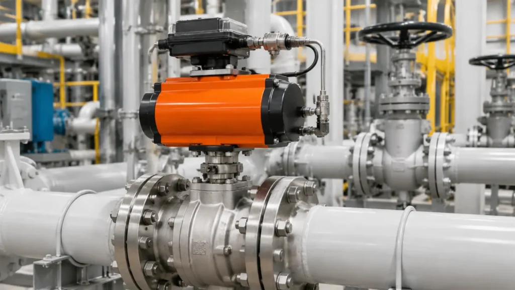
For a clean ball valve in normal on-off service, use 1.20 to 1.30 as an initial actuator sizing range. For emergency or fail-safe service, about 1.50 may be used when the project or valve supplier requires a separate margin. For low-temperature service, first correct the valve torque for the lowest operating temperature, then apply any remaining margin.These values are starting points, not fixed rules. The actuator must provide enough torque at every important point in the valve stroke under the lowest available supply condition. Its maximum output must also stay below the limits of the valve stem, coupling and mounting parts. ISO 5115:2023 treats the valve, actuator and mounting kit as one part-turn actuated assembly and covers pneumatic, hydraulic, electro-hydraulic and electric actuators.[1] Service Initial sizing range Main condition Clean, regular on-off service 1.20–1.30 Reliable valve torque data is available Emergency or fail-safe service About 1.50 Use only when a separate project margin is required Low-temperature service Cold torque × required margin Do not use room-temperature torque directly Dirty, abrasive or crystallizing service Valve-specific Obtain service data from the valve supplier What the Safety Factor Means A safety factor adds extra torque above the corrected torque required by the valve. Trequired = Tvalve × SF If a valve requires 200 N·m and the selected factor is 1.25: 200 × 1.25 = 250 N·m The actuator must provide at least 250 N·m at the same valve position where the 200 N·m load occurs. The following values show how different factors change the required actuator torque. These are calculation examples, not torque values for a specific valve model. Safety factor Valve torque Required actuator torque Extra torque 1.10 200 N·m 220 N·m 20 N·m 1.20 200 N·m 240 N·m 40 N·m 1.25 200 N·m 250 N·m 50 N·m 1.30 200 N·m 260 N·m 60 N·m 1.50 200 N·m 300 N·m 100 N·m A 20% margin means a factor of 1.20. A 50% margin means a factor of 1.50. The factor is multiplied by the valve torque. A service correction is different from a safety factor. A service correction covers a known condition such as: Low temperature Dry gas Special seat material Long periods without operation Sticky or crystallizing media When the valve supplier uses a multiplication method, the calculation may be written as: Tdesign = Tbase × Kservice × Kmargin Do not use this formula automatically. Some suppliers already include the service correction and final margin in their recommended actuator torque. Adding another factor would oversize the actuator. Factors must also be multiplied correctly. A temperature factor of 1.40 followed by a margin of 1.20 gives: 1.40 × 1.20 = 1.68 The total increase is 68%, not 60%. Check the Torque Data First Most sizing errors begin with the wrong valve torque. Before applying any factor, find out what the supplied number represents. Torque value What it usually means What to do Basic valve torque Torque under stated test conditions Add the required service corrections and margin Maximum operating torque Expected maximum under stated conditions Confirm what is already included Corrected valve torque Torque after one or more service corrections Add only corrections that are still missing Recommended actuator torque Minimum actuator output selected by the valve supplier Do not add another factor without approval Confirm the following before sizing: Valve type, model and size Pressure class Floating or trunnion-mounted construction Seat and packing materials Pressure used in the torque chart Minimum and maximum temperature Process medium Opening and closing direction Break, running and reseating torque Whether service factors are already included Maximum allowable stem torque A larger factor cannot correct missing data. If the pressure basis, seat material or temperature is unknown, increasing the factor from 1.25 to 1.50 does not make the result reliable. For more detail, read the ball valve torque curve guide. Use the Correct Pressure Do not assume every torque chart uses differential pressure. Depending on the valve and manufacturer, the chart may use: Maximum differential pressure Maximum operating line pressure Design pressure A stated test pressure Follow the pressure basis printed in the valve torque chart. Differential pressure is the difference between upstream and downstream pressure. If upstream pressure is 50 bar and downstream pressure is 48 bar, the differential pressure is 2 bar. However, a chart based on line pressure may still require the 50 bar value. Upstream pressure Downstream pressure Differential pressure 10 bar 8 bar 2 bar 30 bar 10 bar 20 bar 50 bar 48 bar 2 bar 50 bar 0 bar 50 bar Pressure class is not the same as operating pressure. ASME B16.34 covers valve pressure-temperature ratings, materials, dimensions, testing and marking, but it does not give one actuator safety factor for every valve.[2] ISO 14313:2025 covers the design, manufacture, materials, assembly and testing of pipeline valves and supplements API Specification 6D, 25th edition.[3] API states that API 6D defines manufacturing requirements for pipeline and piping valves.[4] Check the Valve Design Floating and trunnion-mounted ball valves carry pressure loads differently. Their torque values should not be exchanged. Floating ball valves: Pressure moves the ball slightly toward the downstream seat. This helps the valve seal but can increase contact load and operating torque. The effect depends on ball size, pressure, seat area, seat material and packing friction. Trunnion-mounted ball valves: The ball is supported by trunnions. The seats move toward the ball. Seat spring load, cavity pressure, pressure direction and seat design affect the torque. A torque value for a small forged soft-seated floating ball valve should not be applied to a large trunnion valve. See the floating and trunnion ball valve comparison for the main structural differences. Read the Torque Curve A ball valve does not require the same torque throughout its 90-degree movement. Torque point Meaning Why it matters BTO Break to open Overcomes static seat and packing friction RTO Run to open Moves the ball toward the open position ETO End to open Completes the opening stroke BTC Break to close Starts the closing stroke RTC Run
How to Calculate Maximum Allowable Stem Torque for a Ball Valve | MAST, Stem Strength, Actuator Limits
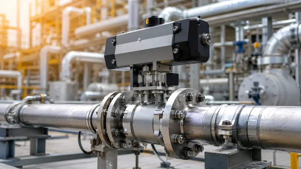
Calculate ball valve MAST by checking the valve manufacturer’s allowable torque, the strength of the weakest stem section, the internal ball drive, and every external part that transmits torque. The actuator must provide enough torque to operate the valve at minimum supply, while its highest possible output must remain below the lowest allowable torque in the complete drive system.The two checks are: Tactuator,min(θ) ≥ Tvalve(θ) × SF Tactuator,max(θ) ≤ Tsystem,allow All values must refer to the same mechanical point, normally the valve stem input. MAST and Operating Torque MAST and operating torque are different values. Operating torque is the torque needed to turn the ball. It includes seat friction, packing friction, bearing friction, differential pressure, temperature effects, contamination, and static friction after a long idle period. MAST is the maximum torque allowed at the valve stem input under the conditions stated by the valve manufacturer. Ball valve torque normally changes during the 90° stroke: Break-to-open torque: Torque needed to start opening Running torque: Torque needed while the ball is moving End-to-open torque: Torque near the fully open position Break-to-close torque: Torque needed to start closing Reseating torque: Torque needed as the ball enters the seat Break torque is often high, but it is not always the highest value. Seat design, pressure direction, packing load, temperature, and deposits can move the highest load to another part of the stroke. See this guide on how to read a valve torque curve. Torque Window Example The actuator must fit inside a safe torque window. It cannot be too small or too powerful. Item Example Value Meaning Raw valve torque 380 N·m Valve demand before applying a factor Operating factor 1.30 Example project factor Required torque 494 N·m 380 × 1.30 Minimum actuator output 540 N·m Output at minimum available supply Maximum actuator output 610 N·m Highest credible transmitted torque System allowable torque 650 N·m Lowest allowable value in the torque path The operating margin is: 540 – 494 = 46 N·m 46 / 494 × 100 = 9.3% The overload margin is: 650 – 610 = 40 N·m 40 / 650 × 100 = 6.2% These are teaching values, not universal minimum margins. Project specifications and manufacturer tolerances decide whether the margins are acceptable. Confirm What MAST Includes A published MAST value may cover: The stem only The stem and stem-to-ball connection The complete internal valve drive One stem material or heat-treatment condition One stated temperature range A value that already includes a design margin Before using the value, confirm: Whether it applies to the stem only or the complete internal drive Which material and heat treatment it covers At what temperature it is valid Whether it includes the key, spline, stem tang, or ball slot Whether it is an allowable value or a tested failure value Whether a design factor is already included The installed system may have a lower limit than the valve MAST: Tsystem,allow = minimum allowable torque of the valve, coupling, key, mounting kit, gearbox, and actuator drive Component Example Allowable Torque Valve internal drive 900 N·m Coupling 820 N·m Key 760 N·m Mounting bracket 1,000 N·m Gearbox output 950 N·m The system limit is 760 N·m because the key has the lowest verified capacity. Use One Torque Reference Torque may be listed at different points: Motor shaft Gearbox input Gearbox output Actuator output flange Coupling Valve stem input Convert every value to the valve stem input before comparing them. For a simple gearbox: Toutput = Tinput × gear ratio × η where η is gearbox efficiency. For example: Input torque: 40 N·m Gear ratio: 20:1 Efficiency: 0.85 Toutput = 40 × 20 × 0.85 = 680 N·m If the catalogue already states gearbox output torque, do not multiply it by the ratio again. Required Data Do not calculate MAST from valve size and nominal stem diameter alone. Valve data: Exact valve model and serial number Size and pressure class Full bore or reduced bore Floating or trunnion-mounted design Seat and packing materials Maximum differential pressure Pressure direction Minimum and maximum temperature Fluid type and solids content Normal and emergency operating cases Opening and closing time Stem data: Minimum circular diameter Internal bore, if hollow Keyways and splines Drive flats and square sections Threads and retaining grooves Cross holes and pin holes Shoulder radii Stem tang dimensions Ball engagement length Manufacturing tolerances Corrosion or wear allowance Material data: Material specification and grade Product form Heat-treatment condition Minimum yield strength Properties at design temperature Impact and hardness requirements Material certificate Actuator data: Minimum and maximum supply pressure Output torque through the complete stroke Spring-start and spring-end torque Electric starting, running, and stall torque Torque-switch setting and accuracy Gearbox ratio and efficiency Maximum manual input Regulator or relief-valve setting Operating speed For actuator type differences, see this pneumatic, electric, and hydraulic actuator selection guide. Data Priority Use data in this order: Approved data for the exact valve serial number or project tag Manufacturer data for the exact valve configuration Manufacturer calculations for the same stem, seat, pressure, and temperature Project-specific engineering calculations Generic product-series tables Simplified hand calculations If a hand calculation gives a higher value than the manufacturer’s MAST, do not automatically use the higher result. The manufacturer may have included an internal weak point that is not shown on the general drawing. Solid Stem Formula For a solid circular stem under elastic torsion: τmax = Tc / J where: T = applied torque c = outside radius J = polar second moment of area τmax = maximum shear stress For a solid circular stem: J = πd4 / 32 c = d / 2 The shear stress becomes: τmax = 16T / πd3 The allowable torque is: Tallow = πd3τallow / 16 This equation applies to circular shafts in elastic torsion. Keyways, flats, grooves, holes, threads, bending, and local contact require additional checks.[1] If diameter is in millimetres and stress is in MPa: Tallow in N·m = πd3τallow / 16,000 Allowable Stress For a basic elastic check of
Why Is My Ball Valve Hard to Operate After Months in Service? | Torque Increase, Seat Swelling, Debris Build-Up
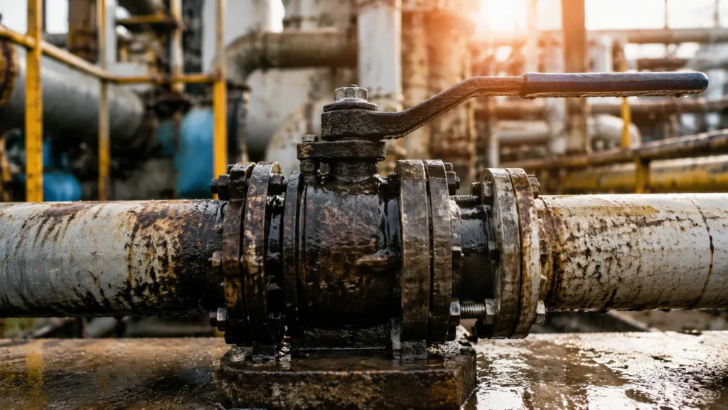
A ball valve usually becomes hard to operate because friction inside the valve has increased or the actuator can no longer provide enough torque. Common causes include seat deformation, debris around the ball, hardened process material, high differential pressure, tight stem packing, corrosion, pipe stress, and actuator faults.Do not fit a longer handle or raise the actuator torque before finding the cause. Stop operating the valve if you hear grinding, see leakage, notice a twisted stem or coupling, receive repeated overload alarms, or cannot reach the fully open or closed position. Check the Symptom The point at which resistance occurs gives the first clue. Symptom Likely cause Hard only when movement starts Seat adhesion, dried product, tight packing, or high breakaway torque Hard through the full stroke Seat deformation, heavy deposits, body distortion, stem damage, or bearing damage Hard near the closed position Debris on the seat, damaged seat, ball misalignment, or incorrect travel stop Hard only under pressure Differential-pressure loading, trapped cavity pressure, or insufficient actuator torque Hard after shutdown Dried product, crystals, wax, freezing, corrosion, or seat adhesion Rough or grinding movement Rust, sand, welding debris, scratched ball, damaged bearing, or metal galling Slow but smooth movement Low actuator output, restricted air supply, high fluid viscosity, or gearbox friction Stops at the same point every time Local deposit, damaged ball, deformed seat, or incorrectly set stop Actuator stalls but the valve turns normally after safe separation Actuator, gearbox, power supply, control accessory, or coupling fault Valve remains tight after the actuator is safely removed Internal valve resistance, packing friction, corrosion, deposits, or seat damage Easier after depressurization Pressure loading is contributing to the torque Harder when hot Seat expansion, pipe movement, cavity pressure, or hot deposits Harder when cold High viscosity, frozen moisture, wax, crystals, or hardened seals Record the conditions while the fault is present: Upstream and downstream pressure Valve-body temperature Opening or closing direction Time since the previous cycle Time required for a full stroke Pneumatic pressure at the actuator while it moves Electric actuator current and alarm records Recent changes to the fluid, cleaning process, pressure, or shutdown method Stroke time is a useful maintenance record. For example, if a valve originally completed its stroke in 5 seconds but now requires 8 seconds under the same operating conditions, the stroke time has increased by 60%: (8 − 5) ÷ 5 × 100% = 60% A 60% increase does not identify the cause by itself, but it confirms that the valve, actuator, supply system, or process condition has changed. Check simple external causes first. A bent handle, engaged locking plate, ice around the stem, loose coupling, deformed bracket, incorrect stop, or water-filled gearbox can make a healthy valve appear stuck. Understand the Torque Valve torque is the turning force needed to rotate the ball. It is not one fixed value throughout the stroke. Breakaway torque starts the valve moving from rest. Running torque keeps the ball moving after the first movement. Reseating torque is needed as the ball returns to the closed sealing position. Long idle periods, pressure loading, sticky product, or tight packing often raise breakaway torque. Heavy deposits, seat deformation, body distortion, or damaged bearings can keep running torque high throughout the stroke. For more detail, see how to read breakaway, running, and reseating torque. The actual torque depends on valve size, bore, seat material, differential pressure, temperature, packing load, fluid condition, operating frequency, and wear. ASME B16.34 covers pressure-temperature ratings, materials, dimensions, examination, testing, and marking for applicable industrial valves.[1] ISO 17292 specifies requirements for metal ball valves used in petroleum, petrochemical, natural-gas, and related industrial applications.[2] Neither standard provides one universal operating torque for every valve and service condition. Check the Valve Design A floating ball valve and a trunnion-mounted ball valve do not respond to pressure in the same way. In a floating ball valve, differential pressure creates a force that moves the ball against the downstream seat. As the pressure difference rises, seat contact force and operating torque can rise. In a trunnion-mounted valve, upper and lower supports hold the ball in position. Torque depends more on seat movement, spring load, bearing condition, cavity pressure, and contamination. See the comparison of floating and trunnion-mounted ball valves before applying one design’s torque behavior to the other. Soft-seated valves are commonly affected by polymer deformation, chemical compatibility, heat, and particles embedded in the seat. Metal-seated valves require closer attention to coatings, sealing surfaces, hard-particle wear, thermal movement, and galling. The differences are explained in this soft-seat versus metal-seat comparison. Keep three torque values separate: The torque required by the valve The torque available from the actuator The maximum torque allowed for the stem, coupling, bracket, and drive parts ISO 5211:2026 covers part-turn actuator attachment dimensions, drive components, and reference torque values for interfaces and couplings.[3] A larger actuator is not automatically safer. If the valve is blocked, excessive actuator torque can twist the stem or damage the coupling and mounting parts. Check Seat Deformation A seat can become tighter around the ball after months of service, but not every deformed seat has chemically swollen. Common seat and seal materials include PTFE, reinforced PTFE, modified PTFE, PEEK, UHMWPE, nylon, proprietary polyamides, NBR, EPDM, and FKM. Their behavior depends on the exact compound, fillers, temperature, pressure, and fluid. Seat deformation normally comes from one or more of these mechanisms: Chemical swelling: The material absorbs fluid and increases in volume. Thermal expansion: The material becomes larger as temperature rises. Creep: The polymer slowly changes shape while held under load. Seat intrusion: Pressure and heat push the seat toward the ball or flow bore. Mechanical damage: Incorrect assembly, particles, or excessive load deform the seat. PTFE generally absorbs little fluid compared with many elastomers. A distorted PTFE seat may therefore be affected by heat, pressure, creep, seat preload, or fillers rather than simple chemical absorption. Possible signs include: High torque through most of the stroke A smaller opening through the seat Seat material pushed out
