
For most ball valve factories, the practical setup is a hydrostatic bench for shell and high-pressure seat tests, plus a pneumatic station for sensitive gas-leak testing. A cryogenic bench is needed when the valve must prove sealing, operation and torque performance at a specified low temperature.
Do not select a test bench by pressure rating alone. Check the effective test diameter, clamping force, valve weight, connection type, pressure range, minimum measurable leakage, test direction and required output per shift.
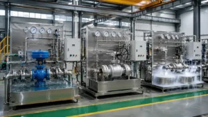
Quick Comparison
| Item | Hydrostatic Bench | Pneumatic Bench | Cryogenic Bench |
|---|---|---|---|
| Main purpose | Shell and high-pressure liquid seat tests | Low-pressure gas seat and external leak tests | Leakage, operation and torque tests at low temperature |
| Common medium | Treated water or another approved liquid | Air, nitrogen, helium or another specified gas | Liquid nitrogen or cold gas for cooling; gas for pressure testing |
| Leak sensitivity | Moderate | High | High at the specified temperature |
| Main risk | High pressure, heavy valves and large separating force | Stored energy in compressed gas | Compressed gas, extreme cold and oxygen displacement |
| Typical test speed | Fast | Medium | Slow |
| Post-test work | Drain and dry the valve | Vent the gas safely | Warm, dry and inspect the valve |
| Best use | Routine factory testing | Gas service and low leakage limits | LNG and other low-temperature services |
A low-pressure gas seat test is not the same as a high-pressure pneumatic shell test. The first checks small seat leaks. The second stores much more energy and requires a test area designed for possible equipment or valve failure.
Example Test Times
The figures below are planning examples for medium-size valves. They are not standard-required test times. Actual times depend on valve size, pressure, filling volume, holding time and customer requirements.
| Example Item | Hydrostatic Test | Pneumatic Test | Cryogenic Test |
|---|---|---|---|
| Setup and connection | 3–10 minutes | 3–10 minutes | 10–30 minutes |
| Stabilization | 2–10 minutes | 3–15 minutes | 30–120 minutes |
| Example total cycle | 10–30 minutes | 10–40 minutes | 2–6 hours |
| Main recorded data | Pressure, time and visible or collected leakage | Pressure, time, temperature and gas leakage | Pressure, temperature, leakage, cycles and torque |
Best Bench by Application
| Valve or Service | Recommended Setup | Important Functions |
|---|---|---|
| Standard industrial ball valves | Hydrostatic bench plus low-pressure gas station | Shell, liquid seat, gas seat and operating tests |
| API 6D pipeline valves | Horizontal hydrostatic bench with several test ports | Bidirectional seat, cavity, drain, vent and torque tests |
| Small high-pressure valves | Compact high-pressure bench | Small test volume, fine pressure control and suitable adapters |
| Metal-seated valves | Hydrostatic and pneumatic bench | Measured leakage and torque recording |
| High-purity gas valves | Clean pneumatic station | Dry gas, clean tubing and verified drying |
| Very low leakage limits | Helium leak station | Background control and a calibrated detector |
| LNG and low-temperature valves | Cryogenic bench | Controlled cooling, temperature recording, gas leakage and torque tests |
Tests a Ball Valve May Need
| Test | What It Checks | Typical Medium |
|---|---|---|
| Shell test | Body, body joints, stem area, plugs and pressure-containing parts | Water |
| High-pressure seat test | Seat sealing at the required liquid pressure | Water or another approved liquid |
| Low-pressure seat test | Small gas leaks across a closed seat | Air or nitrogen |
| Cavity test | Seat behavior when pressure is trapped inside the body cavity | Liquid or gas as specified |
| Torque test | Force needed to open, move and close the valve | Depends on the test condition |
| Cryogenic test | Leakage and operation at low temperature | Cooling medium plus specified test gas |
Pipeline valve orders often require more test connections than standard process valves. CARILO’s guide to API 6D trunnion-mounted ball valves explains the design features that affect the test circuit.
Shell Test
The shell test checks every part that contains internal pressure:
- Valve body and body joints
- Body cover or closure
- Stem sealing area
- Drain and vent plugs
- Sealant injection fittings
- Pressure-containing welds
The valve must be positioned so the test liquid reaches the body cavity, body joints and stem area. For many ball valves, the ball is placed partly open. The final position must follow the approved test procedure.
The operator checks for visible leakage, seepage through the body, stem leakage, cracks and permanent deformation.
A pressure drop does not automatically mean the valve body is leaking. Other possible causes include:
- Trapped air
- Changing water temperature
- Hose expansion
- Seal compression
- Test-head movement
- Pressure-sensor drift
If leakage is found, fully depressurize the system before tightening bolts, plugs or packing.
Seat Design and Test Direction
A seat test applies pressure to one side of a closed valve and measures leakage from the other side or through the body cavity.
A bidirectional valve may need testing from both ends. Passing in one direction does not prove that the opposite seat performs in the same way.
The test circuit must follow the actual pressure path inside the valve. This is why the difference between floating and trunnion-mounted ball valves matters.
In a floating ball valve, pressure moves the ball slightly toward the downstream seat. This movement helps the downstream seat seal. Dirt, a fine scratch on the ball or a damaged polymer seat can cause a gas leak even when the water test passes. CARILO’s forged soft-seated ball valves show a common floating-ball arrangement.
In a trunnion-mounted valve, the ball is mechanically supported. Spring-loaded seat rings move toward the ball. The approved valve drawing should show which port must be pressurized and where leakage must be measured.
A single-piston-effect seat normally uses line pressure to improve sealing and can release excessive cavity pressure in its designed direction. A double-piston-effect seat can seal against pressure from either side, but the body cavity may require an external relief device.
DBB, DIB and Cavity Tests
A double block and bleed arrangement provides two sealing barriers with a bleed or drain path between them.
A double isolation and bleed arrangement provides two sealing barriers against pressure from one source, with a bleed or drain path between them.
The exact meaning, test direction and acceptance method must follow the valve drawing and purchase specification. Compact process systems may use a dedicated DBB compact manifold.
Liquid trapped inside a closed ball valve cavity can expand as it becomes warmer. A typical cavity test may include:
- Close the valve.
- Apply pressure through the approved cavity connection.
- Monitor both valve ends.
- Confirm where the cavity pressure is released.
- Record the pressure behavior.
- Reduce cavity pressure.
- Check that the seat seals again.
This is a general test path. The test pressure, direction and acceptance limit must follow the specified seat design and standard.
Torque Test
A valve can pass its leakage tests but still require too much force to operate.
Useful torque measurements include:
- Break-to-open torque
- Running torque
- End-to-close torque
- Torque under differential pressure
- Torque after repeated cycles
- Torque at low temperature
The report should state the pressure, temperature, operating speed, test direction, seat material and point where torque was measured.
An oversized actuator can hide a valve problem. Actuator sizing should consider maximum pressure difference, minimum air supply, seat wear, low temperature and a suitable operating margin.
Metal-seated ball valves can have higher torque and different allowable leakage from soft-seated designs. Do not apply a soft-seat leakage limit to a metal-seat valve unless the contract requires it.
Hydrostatic Test Bench
A hydrostatic bench is normally the main production machine for factories that perform shell and liquid seat tests.
A practical bench includes:
- Valve support frame
- Adjustable test heads
- Hydraulic or mechanical clamping
- Low-pressure filling pump
- High-pressure pump or intensifier
- High-point air vent
- Pressure transmitters
- Reference pressure gauge
- Water tank and filter
- Drain and recovery circuit
- Pressure-relief device
- Clamp and guard interlocks
- Test-data system
A typical water path is:
Tank → filter → filling pump → valve → high-point vent → high-pressure pump → isolation valve → pressure sensor → controlled drain → recovery tank.
The filling pump moves water quickly at low pressure. The high-pressure pump raises the pressure after the valve is full and trapped air has been removed.
Clamping Force
Maximum pump pressure does not show whether the machine can safely hold the valve.
The basic pressure thrust is:
Separating force = Test pressure × Effective pressurized area
The effective diameter is the diameter enclosed by the test-head seal. It is not always equal to the valve bore or nominal pipe size.
| Effective Diameter | Test Pressure | Calculated Separating Force |
|---|---|---|
| 100 mm | 10 MPa | 78.5 kN, about 8.0 metric tons-force |
| 200 mm | 10 MPa | 314 kN, about 32 metric tons-force |
| 300 mm | 10 MPa | 707 kN, about 72 metric tons-force |
| 300 mm | 16 MPa | 1,131 kN, about 115 metric tons-force |
| 400 mm | 16 MPa | 2,011 kN, about 205 metric tons-force |
At the same pressure, doubling the effective diameter increases the separating force by about four times because the pressurized area increases with the square of the diameter.
These figures are pressure thrust only. They are not the final machine ratings. The final clamping capacity must also allow for load misalignment, frame movement, test-head deflection, seal compression, manufacturing tolerance and the required design margin.
The equipment supplier should provide calculations for the frame, tie bars, clamps, test heads, adapters and foundation. The control system should stop pressurization if clamping force falls below its safe value.
Test Heads
Test heads must seal the valve without damaging its end connections.
Common options include:
- Flange-face sealing heads
- Internal radial seals
- Threaded adapters
- Socket-weld adapters
- Butt-weld end adapters
- Blind-flange assemblies
An internal radial seal can shorten setup time, but it works only when the bore, wall and end geometry are suitable.
A flange-face seal is easier to inspect but may take longer to install.
Do not weld temporary closures onto butt-weld ends unless an approved procedure allows it. Welding and removal can damage the valve end or change its material condition.
Pressure Control
A controlled hydrostatic cycle is:
- Fill the valve.
- Vent trapped air.
- Raise pressure slowly.
- Allow pressure and temperature to settle.
- Start the official holding time.
Do not start timing as soon as the gauge first reaches the target pressure.
Where leakage is judged by pressure stability or collected liquid, isolate the pressure source during the official measurement period. A running pump can replace lost water and hide leakage.
Pressure Sensor Range
One high-range transmitter may not measure a low pressure accurately.
The following example applies only when accuracy is stated as a percentage of full scale:
| Sensor Range | Example Accuracy | Maximum Full-Scale Error | Error Compared with a 1 MPa Test |
|---|---|---|---|
| 0–100 MPa | ±0.5% FS | ±0.50 MPa | 50% |
| 0–10 MPa | ±0.5% FS | ±0.05 MPa | 5% |
| 0–2 MPa | ±0.5% FS | ±0.01 MPa | 1% |
A transmitter suitable for a 60 MPa shell test may therefore be unsuitable for a 1 MPa gas test.
Some sensors state accuracy as a percentage of reading or use a combined formula. The supplier must explain how the stated accuracy is calculated.
A wide-range bench may need separate low-, medium- and high-pressure transmitters, automatic range selection and overpressure protection for the lower-range sensors.
More decimal places on the display do not mean better accuracy. The sensor range, calibration and complete measurement circuit determine the useful result.
Water Quality and Drying
Dirty test water can damage the valve or create a false leak.
Common problems include:
- Particles scratching the ball or seat
- Oil contaminating oxygen or high-purity valves
- Deposits blocking small passages
- Rust or seal fragments entering the seat area
- Water remaining inside the body cavity
The system should include suitable filtration, regular tank cleaning and a defined water-replacement schedule.
There is no single water-quality or chloride limit that fits every valve. Use the valve material specification, service-cleanliness requirement and purchase order.
Drying methods include gravity drainage, dry-air blowing, nitrogen purging, heated dry air, vacuum drying and dew-point measurement.
A fixed blowing time does not prove that the valve is dry. Water may remain in the cavity, drain connection or seat pocket. Oxygen, hydrogen, high-purity gas and cryogenic valves may require a controlled drying and cleanliness procedure.
Pneumatic Test Bench
A pneumatic bench is used when small gas leaks must be measured.
A typical system includes:
- Air or nitrogen supply
- Gas booster where needed
- Coarse and fine pressure regulators
- Automatic isolation valves
- Pressure transmitters
- Leakage meter
- Automatic vent valve
- Pressure-relief device
- Safe exhaust line
- Remote controls
Gas should enter the valve in controlled steps. Opening a large gas supply directly into an empty valve can cause pressure shock, gas heating and unstable readings.
Compressed-gas containers and related equipment must be handled and used under applicable safety requirements.[1]
Gas Leakage Methods
| Method | Best Use | Main Limitation |
|---|---|---|
| Manual bubble counting | Simple routine checks | Bubble size and operator judgment vary |
| Electronic bubble counting | Repeatable production testing | Tube size and water depth affect the result |
| Mass-flow meter | Numerical leakage measurement | The meter range and gas calibration must match the test |
| Pressure decay | Small sealed test volumes | Temperature and test volume affect the result |
| Helium detector | Very low leakage limits | Higher cost and background helium control |
Leakage Units
Common leakage units include:
- cm³/min
- sccm, or standard cubic centimeters per minute
- Nm³/h, or normalized cubic meters per hour
- mbar·L/s for some tracer-gas tests
- Bubbles per minute
Standard and normalized flow values are converted to stated reference temperature and pressure conditions. Do not compare two leakage values unless the gas, unit and reference conditions are known.
Bubble and Flow Testing
A bubble test sends leakage gas through a tube below the water surface. The procedure should state the tube diameter, water depth, gas pressure, stabilization time, counting time and maximum bubble count.
Water depth creates backpressure. Different tube sizes and water depths may produce different bubble patterns for the same leakage rate. Manual bubble counting is not ideal when the result is close to the acceptance limit.
A mass-flow meter gives a numerical leakage value. Its range should be close enough to the acceptance limit to provide useful resolution.
The ranges below are instrument-selection examples, not universal valve leakage limits.
| Example Acceptance Limit | Possible Meter Range | Oversized Range with Poorer Resolution |
|---|---|---|
| 5 sccm | 0–10 or 0–20 sccm | 0–1,000 sccm |
| 50 sccm | 0–100 sccm | 0–10,000 sccm |
A small meter can be overloaded by a major leak. A practical circuit may use a large-leak precheck, bypass line, several meter ranges, automatic range selection and overrange protection.
The meter calibration must suit the test gas. Air, nitrogen and helium may produce different readings on an instrument that has not been configured for that gas.
Pressure-Decay Testing
A pressure-decay test isolates a known volume and measures the pressure change over time.
The result is affected by leakage rate, closed volume, gas temperature, test duration, sensor resolution and movement of hoses and seals.
Under the same ideal test conditions, pressure change is approximately inversely related to the closed volume:
| Closed Test Volume | Relative Pressure Change from the Same Leak |
|---|---|
| 2 L | 100% reference value |
| 10 L | About 20% |
| 50 L | About 4% |
| 100 L | About 2% |
This comparison assumes the same gas, initial pressure, temperature, test duration and leakage mass flow. It explains why pressure decay is usually easier to measure on a small valve than on a large valve.
Temperature can also look like leakage. In a sealed constant-volume system, cooling an ideal gas from 25°C to 24°C reduces its absolute pressure by about 0.34%, even when there is no leak.
| Initial Absolute Pressure | Temperature Change | Approximate Pressure Drop without Leakage |
|---|---|---|
| 0.5 MPa | 25°C to 24°C | 1.68 kPa |
| 1.0 MPa | 25°C to 24°C | 3.35 kPa |
| 2.0 MPa | 25°C to 24°C | 6.71 kPa |
Allow the valve and gas to stabilize before starting the measurement. A sealed blank or calibrated reference leak can help separate normal system drift from actual valve leakage.
Pneumatic Safety
The risk of a pneumatic test depends on pressure, gas volume, valve volume, connected pipework and the parts that may fail.
A suitable system should include:
- Remote pressurization
- Restricted access during testing
- Clamp-position monitoring
- Slow pressure increase
- Independent pressure relief
- Controlled venting
- Emergency depressurization
- A barrier or test area designed for the expected failure
A thin cover that stops water spray may not stop a broken adapter or flange part.
Operators must not tighten fittings, bolts, plugs or packing while the valve is pressurized.
Cryogenic Test Bench
A cryogenic bench checks whether the valve still seals and operates at the specified low temperature. CARILO’s forged cryogenic ball valves show typical extended-stem and low-temperature configurations.
Low temperature can cause:
- Metal contraction
- Seat-clearance changes
- Hardening of soft seals
- Packing contraction
- Higher operating torque
- Changes in body-joint loading
- Frozen moisture
A typical cryogenic station includes:
- Insulated cold box or tank
- Liquid-nitrogen supply
- Controlled cooling system
- Several temperature sensors
- Gas pressure circuit
- Leakage meter
- Torque sensor
- Remote valve operation
- Oxygen monitor
- Ventilation and controlled exhaust
ISO 28921-1:2022 covers the design, manufacture and production testing of specified isolation valves for service from −50°C down to −196°C.[2]
ISO 28921-2:2015 covers type testing of isolation valves for low-temperature applications.[3]
Cooling and Temperature Measurement
Partial immersion cools the main valve body while keeping the extended bonnet and packing area warmer. This can better represent many installed cryogenic valves.
Full immersion places the complete valve in the cold environment. Use it only when the approved procedure and valve design allow it.
Cold gas cooling circulates low-temperature gas around the valve. It can provide smoother temperature control but may take longer.
These methods create different temperatures at the body, seats, stem and packing. They should not be exchanged without technical review.
One sensor on the outside of a large valve may not show whether the seats and cavity are cold enough. The table below is an example for a large trunnion-mounted valve, not a fixed standard requirement.
| Example Measuring Position | Example Sensor Quantity |
|---|---|
| Lower and upper body | 2 |
| Upstream and downstream seat areas | 2 |
| Body cavity | 1 |
| Bonnet or stem extension | 1 |
| Packing area | 1 |
| Gas inlet and outlet | 2 |
| Total | 9 |
The approved test procedure determines the final number and locations. The test should begin only after all required measuring points reach and hold the specified temperature. The liquid-nitrogen bath temperature alone does not prove that the valve seats have reached the target.
Cryogenic Test Sequence
- Complete the required room-temperature tests.
- Install and check the temperature sensors.
- Cool the valve at the specified rate.
- Wait until the required temperatures are stable.
- Apply the specified gas pressure.
- Measure seat, stem and body-joint leakage.
- Operate the valve through the required cycles.
- Measure opening and running torque.
- Repeat the required leakage tests.
- Warm the valve in a controlled way.
- Inspect and retest it at room temperature where required.
Common errors include ice blocking a leakage line, cold gas entering an unsuitable meter, long tubing delaying the reading and incoming gas warming the valve.
Liquid nitrogen can displace oxygen and create a dangerous atmosphere. OSHA recommends hazard analysis, oxygen detection, alarms, emergency ventilation and worker training where nitrogen releases may affect occupied areas.[4]
Standards Comparison
| Standard | Main Role | Practical Meaning |
|---|---|---|
| API 598 | Valve inspection and pressure testing | Used with a product standard or purchase agreement |
| ISO 5208 | Pressure testing of metallic industrial valves | Covers pressure-boundary and closure-tightness tests |
| API 6D | Pipeline and piping valve product specification | May require cavity and special seat tests |
| API 608 | Metal ball valve product standard | Works with referenced test requirements |
| ASME B16.34 | Ratings, construction, materials, testing and marking | Broader than a pressure-test procedure |
| MSS SP-61 | Shell and seat-closure pressure testing | Common in general industrial specifications |
| ISO 28921 | Low-temperature isolation valves | Separates production testing from type testing |
| ISO 15848 | Fugitive-emission testing | Checks external leakage from stems and body joints |
Key Standards
API 598 covers inspection, examination and pressure testing for several valve types, including ball valves. API lists the current publication as the 11th Edition, issued in February 2023.[5]
A suitable API 598 test bench should support shell tests, high-pressure closure tests, low-pressure closure tests where required, correct test direction, controlled holding time and recorded leakage results. API 598 is a test standard; it does not replace the full valve product standard.
ISO 5208:2015 covers pressure-boundary integrity, closure tightness and the structural adequacy of the closure mechanism for metallic industrial valves.[6]
An ISO leakage class should not automatically be treated as equal to an API leakage requirement. A specification using the words “zero leakage” should still state the medium, pressure, duration, direction, unit, measurement method and instrument range.
No measuring system proves absolute zero leakage. It can only show that leakage is below the detection limit of the stated method.
API 6D is a product specification for pipeline and piping valves. Depending on the valve design and order, the test equipment may need bidirectional seat testing, body-cavity connections, drain and vent testing, cavity-relief testing, DBB or DIB testing, and operating or torque tests.
API currently lists API 6D as the 25th Edition with Addendum 3 published in March 2025.[7]
Before approving a test procedure, check the contract edition and all applicable API addenda and errata.[8]
API 608 is a product standard for metal ball valves with flanged, threaded and welding ends. API confirmed implementation of the 7th Edition in October 2025.[9]
Passing an API 598 pressure test does not prove that all API 608 design, material, marking and documentation requirements have been met.
ASME B16.34-2025 covers pressure-temperature ratings, dimensions, tolerances, materials, nondestructive examination, testing and marking for several valve constructions.[10]
A valve may be designed to ASME B16.34 and pressure-tested under API 598 or another specified test standard. The purchase order should state which requirement takes priority if the documents differ.
MSS SP-61-2019 establishes requirements and acceptance criteria for valve shell and seat-closure pressure testing.[11]
Do not replace an MSS test with an API or ISO test without checking the purchase order. Test pressures, durations and leakage rules may differ.
ISO 15848-1:2015 covers classification and type-testing procedures for external leakage from valve stems, shafts and body joints.[12]
ISO 15848-2:2015 covers production acceptance testing where fugitive-emission requirements are specified.[13]
A standard hydrostatic bench cannot prove fugitive-emission or fire-safe qualification simply by applying a higher pressure.
How to Select a Test Bench
Give the equipment supplier a complete valve matrix containing:
- Minimum and maximum valve size
- Maximum valve weight
- Minimum and maximum face-to-face length
- Pressure classes
- Maximum shell and seat pressures
- Minimum controlled pressure
- End connection types
- Floating or trunnion design
- SPE, DPE, DBB and DIB requirements
- Test media
- Leakage limits and units
- Required standards and editions
- Valves required per shift
- Required test-report format
A large universal machine is not always efficient. Testing a 2-inch valve on equipment sized for a 36-inch valve creates more dead volume, longer filling time, larger adapters and poorer low-flow measurement.
Production Capacity
Theoretical output can be estimated by dividing the available shift time by the complete test cycle.
| Complete Cycle per Valve | Theoretical Full Cycles in an 8-Hour Shift |
|---|---|
| 10 minutes | 48 valves |
| 12 minutes | 40 valves |
| 13 minutes | 36 valves |
| 15 minutes | 32 valves |
| 20 minutes | 24 valves |
For example, a 13-minute cycle may include 3 minutes for loading, 2 minutes for filling and venting, 5 minutes for stabilization and holding, and 3 minutes for drainage and unloading.
Actual output will be lower after product changes, operator breaks, maintenance and failed tests. A target of 40 valves per shift therefore needs a cycle shorter than 12 minutes, overlapping work or a second station.
Factory and Site Acceptance
Before ordering a test bench, ask the supplier to provide:
- Clamping-force calculation
- Frame and tie-bar calculation
- Test-head and adapter ratings
- Pressure accuracy at high and low ranges
- Leakage-meter ranges and resolution
- Fixture leakage test
- Safety-interlock demonstration
- Emergency depressurization test
- Calibration records
- Spare-parts list
- Failed-test audit trail
The factory acceptance test should include the largest valve, smallest valve, highest pressure, lowest controlled pressure and smallest required leakage range.
The site acceptance test should check the installed electrical supply, water, gas, ventilation, drainage, foundation, lifting access, calibration and actual production cycle. CARILO’s industrial valve service page provides information on engineering, inspection and documentation support.
Test Records
Every result should be linked to one valve and include:
- Customer and order number
- Valve serial number
- Size and pressure class
- Body and seat materials
- Seat design
- Test standard and edition
- Test medium
- Pressure, duration and direction
- Leakage result and unit
- Temperature and torque where required
- Instrument and calibration details
- Operator and test date
- Pressure and temperature curves
Keep failed tests as well as final passed tests. Repeated failures may show damaged seats, poor ball finish, assembly errors, dirty water or a leaking fixture.
Troubleshooting
| Problem | Possible Cause | What to Check |
|---|---|---|
| Pressure falls with no visible leak | Temperature change, trapped air, hose movement, fixture leakage or sensor drift | Record temperature and test the fixture with a sealed blank |
| Water test passes but gas test fails | Fine scratch, dirt or small seat damage | Clean and inspect the ball and seat |
| Bubble count changes between operators | Different water depth, tube size or counting method | Standardize the setup or use an electronic counter |
| Flow meter reaches full scale | Major leak or incorrect meter range | Use a large-leak precheck and protect the small meter |
| Pressure decay is too small on a large valve | Test volume is too large | Use direct flow measurement |
| Low-temperature torque rises sharply | Reduced clearance, seat contraction or lubricant change | Review the torque curve and temperature readings |
| No cryogenic leakage reading | Ice or condensation blocking the line | Warm, dry and inspect the measurement line |
| Water remains after drying | Trapped cavity or poor valve position | Change the valve orientation and verify final dryness |
Conclusion
For most factories, use a hydrostatic bench for shell and high-pressure seat tests and a separate gas station for sensitive leakage checks. Add a cryogenic bench only when low-temperature performance must be verified. Check clamping force as carefully as pump pressure: a 300 mm effective diameter at 16 MPa creates about 1,131 kN of separating force. Select pressure and flow sensors close to the required range, stabilize gas temperature before pressure-decay testing, and calculate output from the complete cycle. A 13-minute cycle allows only 36 full tests in eight hours before breaks, changeovers or failed retests.







