
Which Direction Should a Cryogenic Ball Valve Be Installed? | Cavity Relief, Flow Arrow, Stem Orientation
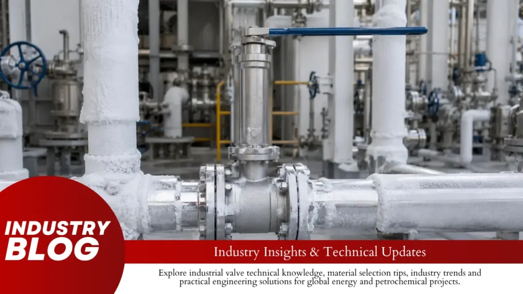
Install a cryogenic ball valve according to its valve-specific pressure direction, cavity-relief path, and permitted stem angle. On many unidirectional floating ball valves, a relief hole in the ball faces the manufacturer-designated pressure side when the valve is closed. The extended bonnet normally points upward in cryogenic liquid service. Do not decide the direction from normal pipe flow, handle position, or flange shape alone. ISO 28921-1:2022 covers metallic isolation valves designed for temperatures from −50°C to −196°C, including cryogenic ball valves. It does not give one universal installation direction for every valve design. The model-specific drawing and installation manual remain the final reference.[1] This article mainly applies to two-way cryogenic isolation ball valves. Three-way valves, control valves, liquid-hydrogen valves, and special cavity-free designs may use different rules. Product construction and available configurations can be reviewed on the forged cryogenic ball valve page. Check Four Items Before installation, confirm four separate items: Normal flow: the direction in which the fluid usually moves while the valve is open. Pressure side: the side expected to have the higher pressure when the valve is closed. Relief side: the side that receives pressure released from the valve body cavity. Stem position: the installed angle of the stem and extended bonnet. These four items do not always point in the same direction. A tank line may carry liquid in one direction during filling and the opposite direction during withdrawal. A pump trip, check-valve leak, or tank backpressure can also move the higher pressure to the opposite side of a closed valve. A correct installation therefore needs more than a visible flow arrow. It requires one confirmed pressure side, one confirmed cavity-relief destination, and one approved stem position. Know the Temperature Cryogenic valves work at temperatures where common seal materials, body materials, and installation methods may no longer behave normally. Fluid Approximate Normal Boiling Temperature Installation Concern LNG / methane About −162°C Cold contraction, packing temperature, and trapped-liquid pressure Liquid oxygen About −183°C Oxygen cleanliness, ignition control, and material compatibility Liquid argon About −186°C Cold shrinkage, trapped liquid, and asphyxiation risk Liquid nitrogen About −196°C Maximum cold commonly used during cryogenic valve testing Methane has a normal boiling point near 111.7 K, or about −161.5°C.[6] Oxygen boils near 90.2 K, or about −183°C.[7] Argon boils near 87.3 K, or about −186°C.[8] Nitrogen boils near 77.3 K, or about −196°C.[9] In a liquid-nitrogen line, the lower valve body may be close to −196°C while the upper bonnet is exposed to an ambient temperature near 20°C. The temperature difference across the bonnet can therefore exceed 200°C. This is why bonnet length, stem direction, insulation height, and packing location matter. For related material, bonnet, and leakage-test requirements, see the cryogenic valve selection guide. Read the Markings Check the valve body, nameplate, bonnet pad, stem plate, and approved assembly drawing. Do not assume that every arrow means normal process flow. Depending on the design, an arrow may show: The preferred process-flow direction The manufacturer-designated low-pressure side The preferred sealing direction The direction required by a vented-ball design Use this order when checking the valve: Confirm the model and serial number. Read all body and nameplate markings. Confirm whether the valve is unidirectional or bidirectional. Review the sectional or general arrangement drawing. Identify the cavity-relief method. Compare the valve direction with the P&ID and operating conditions. If the drawing, arrow, and project data do not agree, do not install or pressurize the valve until the manufacturer confirms the correct direction. Do Not Trust the Handle A two-way ball valve normally moves through about 90° from fully open to fully closed. The handle usually sits parallel to the pipe when the valve is open and perpendicular to the pipe when it is closed. This shows the position of the main ball bore. It does not prove which way a drilled relief hole faces. The handle or actuator indicator can also be wrong when: The handle was reinstalled in the wrong position. The actuator coupling is one quarter-turn out of position. The closed stop is set too early. The ball does not reach its true closed position. The position indicator does not match the stem. Even a small travel error can leave part of the ball port exposed to the seat or place the relief hole between its intended positions. Confirm the internal position from the assembly drawing and mechanical stops. Find the Cavity The body cavity is the space between the outside of the ball, the valve seats, and the inside wall of the valve body. Cryogenic liquid can remain in this space after the valve moves. Heat then enters through the body, bolts, bonnet, connected pipe, and surrounding air. Part of the liquid changes into vapor while the cavity volume remains almost fixed. Pressure can rise quickly. OSHA explains that heat entering cryogenic liquid can cause vaporization and pressure buildup in containers and transfer systems. Suitable pressure relief is needed to prevent pressure-related failure.[3] Excess cavity pressure can damage or overload: Valve seats Body seals Stem packing Bonnet seals Body joints Small relief connections Liquid may be trapped with the valve open, closed, or in both positions, depending on the ball, seat, and body design. API 6D requires the manufacturer to determine whether open-position or closed-position trapping is possible. If liquid trapping is possible, a covered valve must have automatic cavity relief.[4] Drilled Ball Relief Many unidirectional cryogenic floating ball valves use a small relief hole drilled into one side of the ball. When the valve is closed, the hole connects the body cavity to one pipeline port. On a common upstream-relieving design, the hole faces the manufacturer-designated pressure side. The valve closes. Liquid remains around the outside of the ball. The trapped liquid absorbs heat. Part of the liquid changes into vapor. Cavity pressure increases. The drilled hole releases the pressure to the designated pipe side. The hole does not connect the two pipeline ends. It connects only the enclosed body cavity to one side of the line. If the
Which Ball Valve Materials Work in Amine Service? | Stress Corrosion Cracking, NACE Limits, Seal Selection
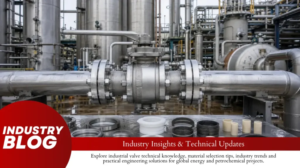
Carbon steel, 316L stainless steel, duplex stainless steel and nickel alloys can all work in amine-service ball valves, but under different conditions. Carbon steel is often suitable when corrosion, weld repairs, hardness and heat treatment are controlled. Duplex stainless steel is a better choice when hot chlorides make 316L unreliable. Alloy 625 or Alloy C-276 may be needed for severe sour or contaminated service. The body material is only one part of the selection. The ball, stem, seats, O-rings, body gasket and packing must also match the amine concentration, H₂S and CO₂ content, temperature, pressure, chlorides, hydrocarbons and solids. A 30 wt% MEA solution is a common process reference, while MDEA systems may use higher concentrations such as 40–50 wt%. These figures describe the fluid, not a material limit. A 40 wt% MDEA stream can be mild in one plant and highly corrosive in another because of temperature, acid-gas loading, chlorides, oxygen and heat-stable salts. The U.S. Department of Energy’s NETL handbook uses approximately 30 wt% MEA as a commercial process reference.[1] What to Check First Do not approve a valve from the words “amine service” alone. Check at least three operating conditions: normal operation, the worst expected upset and cleaning or steam-out. Information Why It Matters Amine type and concentration MEA, DEA, MDEA, DGA and formulated blends may operate at different concentrations and temperatures. Lean or rich amine Rich amine normally carries more H₂S, CO₂, hydrocarbons and corrosion products. Normal and maximum temperature Temperature affects corrosion, cracking, seat creep, packing friction and elastomer life. Pressure and maximum differential pressure High differential pressure can deform seats, extrude seals and increase operating torque. H₂S and CO₂ content Wet H₂S can introduce sulfide stress cracking and hydrogen damage. Water phase Wet-H₂S cracking needs an aqueous phase. Water may also remain in the valve cavity after draining. Chlorides Hot chlorides can cause pitting, crevice corrosion and chloride stress corrosion cracking in 316L. Heat-stable salts They can increase corrosion and collect in low-flow areas. Hydrocarbon carryover Oil, condensate and compressor lubricant can damage elastomers that perform well in water-based amine. Iron sulfide and other solids Particles can scratch the ball, block seat movement and raise torque. Steam-out and cleaning fluids The valve may see a higher temperature or a different chemical during cleaning. Depressurization rate Fast pressure release can damage gas-saturated elastomer seals. Plant history is also useful. Check whether nearby piping, vessels or older valves have shown carbon steel cracking, 316L pitting, swollen O-rings, stem leakage or rising operating torque. Example Operating Data The following examples show how process data should be presented. They are not universal material limits. Example Service Illustrative Data Main Checks Clean lean MDEA 40 wt% MDEA, 65°C normal, 85°C upset, 40 bar design pressure, 10 bar maximum differential pressure Wet H₂S, chlorides, seat pressure rating and elastomer compatibility Rich sour MDEA 45 wt% MDEA, 90°C normal, 110°C upset, 60 bar design pressure, 40 bar maximum differential pressure SSC, HIC, weld history, rapid gas decompression and iron sulfide Chloride-contaminated amine 40 wt% amine, 85°C, 25 bar, chloride trend rising from 50 to 300 mg/L 316L pitting, deposits, cooling-water leakage and duplex suitability Dirty rich amine 45 wt% amine, 80°C, visible iron sulfide, weekly operation, 30 bar differential pressure Ball coating, seat wear, drain blockage, flushing and actuator torque The chloride figures above show a worsening trend, not a safe or unsafe boundary. Chloride damage also depends on temperature, oxygen, deposits, pH, tensile stress and the stainless steel’s manufacturing condition. Damage Mechanisms Amine-service valves can fail through several mechanisms. One material upgrade will not prevent all of them. Amine stress corrosion cracking: This mainly affects carbon steel under tensile stress. Cracks are often found beside non-PWHT welds, casting repair welds, attachment welds and heavily cold-worked areas. A valve may have little wall loss but still contain a serious crack. Sulfide stress cracking: Wet H₂S can crack susceptible metallic parts when hardness, strength or tensile stress is too high. The body, stem, springs, retaining rings, internal fasteners and weld heat-affected zones all need review. Hydrogen-induced cracking: Hydrogen entering carbon steel can cause HIC, stepwise cracking or blistering. Steel cleanliness, inclusions, product form and local chemistry matter. A single hardness reading does not prove HIC resistance. General and local corrosion: Acid-gas loading, temperature, oxygen, heat-stable salts and poor filtration can increase metal loss. Seat pockets, drain holes and stagnant body cavities may corrode faster than the main pipeline. Chloride attack: Chlorides from makeup water, cooling-water leaks or process contamination can attack stainless steel. Deposits and stagnant liquid make seat pockets and body joints more vulnerable. Particle damage: Iron sulfide and other solids can become trapped between the ball and seat. This may cause scratches, internal leakage or a sharp rise in operating torque. API RP 945, 4th Edition, was published on September 26, 2022. It covers methods used to avoid environmental cracking of carbon steel equipment in amine units, including material, fabrication, inspection and repair controls.[2] NACE and ISO Limits “NACE compliant” is not a complete valve specification. The purchase order must state the standard, edition, affected parts and required material condition. ANSI/NACE MR0103/ISO 17945 is normally used for sour petroleum-refining and related processing environments. AMPP lists ANSI/NACE MR0103/ISO 17945-2023 as the current AMPP publication.[3] ISO publishes ISO 17945:2015. The standard covers resistance to sulfide stress cracking in sour refining environments and includes valve bodies and parts whose failure could affect pressure containment or valve operation. It does not provide valve design rules and does not cover every form of wet-H₂S cracking, corrosion or other failure.[4] ANSI/NACE MR0175/ISO 15156 is mainly used for oil and gas production and natural-gas sweetening plants. ISO 15156-1:2020 states that it is not necessarily suitable for refining or downstream equipment, so it should not automatically replace MR0103 in a refinery amine unit.[5] ISO 15156-3:2020 covers cracking-resistant corrosion-resistant alloys used in H₂S-containing oil and gas production and gas-treatment equipment. It addresses cracking resistance, not general or localized corrosion, and is not automatically a refinery material standard.[6] A
What Is the Best Ball Valve for Oxygen Service? | Degreasing, Material Compatibility, Ignition Risk
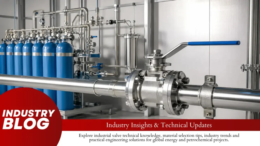
Short answer: For many room-temperature gaseous oxygen isolation lines, a properly designed 316L stainless steel ball valve with a verified PTFE or PCTFE seat can be considered. The valve must be cleaned for oxygen service, opened at a controlled speed, used fully open or fully closed, and checked for pressure, flow velocity, seat material, cavity pressure, particles, and lubricant contamination. Degreasing alone does not make a standard industrial valve suitable for oxygen. Higher pressure, high velocity, frequent venting, pressure letdown, cold gaseous oxygen, or liquid oxygen may require copper-, nickel-, Monel-, or copper-nickel-rich parts with better resistance to burning. Service Possible starting point Main checks Room-temperature gaseous oxygen isolation Oxygen-cleaned 316L valve with a verified fluoropolymer seat Pressure, velocity, opening speed, seat compound, particles, and cleanliness Pressure above the selected metal’s exemption pressure More burn-resistant trim or a different body and trim alloy Metal thickness, pressure-velocity limits, impact points, and fire spread Vent, drain, bypass, or pressure letdown Valve designed for throttling duty High differential pressure, small opening area, and downstream impact Cold gaseous oxygen below −30°C Low-temperature oxygen valve Thermal contraction, packing position, cavity relief, and material toughness Liquid oxygen Dedicated cryogenic oxygen valve Trapped liquid, extended stem, low-temperature testing, and oxygen cleaning Define the Service “Oxygen service” does not give a manufacturer enough information to select a valve. EIGA defines gaseous oxygen as gas containing more than 23.5% oxygen by volume, with the remaining components being inert.[1] EIGA term Oxygen concentration Why it matters Gaseous oxygen Above 23.5% by volume Oxygen-service material and cleaning controls apply. Low-purity oxygen Above 23.5% and up to 35% Some metal velocity rules can be less restrictive under defined conditions. Standard-purity oxygen 99.5% or higher Most published metal flammability data use this purity range. Ultra-high-purity oxygen 99.999% or higher Particle and contamination control usually become more demanding. EIGA Doc 13 covers gaseous oxygen piping from −30°C to 200°C, at pressures up to 21 MPa, with a typical gas dew point of −30°C or lower. Systems outside those limits need additional analysis or testing.[2] Provide these details in the enquiry: Minimum, normal, and maximum oxygen concentration Gaseous oxygen, cold gaseous oxygen, or liquid oxygen Design pressure and maximum operating pressure Maximum pressure difference across the valve Minimum and maximum temperature Normal and maximum mass flow Actual volume flow at line pressure and temperature Pipe size, Schedule, and internal diameter Normal flow direction Manual, pneumatic, electric, or hydraulic operation Required opening and closing time Isolation, venting, draining, bypass, or control duty Required seat-leakage limit Expected moisture, rust, scale, or other particles For oxygen below 35% by volume and pressure up to 21 MPa, EIGA states that hydrocarbon-free ferrous and non-ferrous piping can be exempt from its velocity limits and Appendix B minimum thickness rules. Oxygen cleaning and oxygen-compatible nonmetals are still advised.[3] This exception should not be shortened to “oxygen below 35% is safe.” Oil contamination, polymers, valve friction, rapid compression, and unsuitable geometry can still cause a fire. Choose the Valve Duty Ball valves are well suited to isolation. When fully open, the bore can provide a nearly straight flow path. When closed, a soft seat can provide tight shutoff. A standard isolation ball valve should not be used for regular throttling. During the first part of opening, gas passes through a small crescent-shaped gap. Local velocity can be much higher than the average velocity in the pipe. The exposed ball edge, seat entrance, reducer, bend, tee, or instrument connection can then receive direct particle impact. EIGA treats bypass, vent, drain, emergency shutoff, and other valves working under high differential pressure as throttling duties that need separate review. For piping downstream of a pressure-letdown valve or restrictive orifice, EIGA treats at least eight outlet pipe diameters as an impact and turbulence area. For a DN50 outlet, eight diameters equal about 400 mm of downstream pipe. A 150 μm or finer filter upstream can reduce particle impact, but it does not remove compression, friction, or material risks.[4] A forged soft-seated floating ball valve can be considered for clean on-off service after its materials, operating method, and cleaning procedure have been approved. It should not be selected from pressure class and body material alone. Use a purpose-designed control or throttling valve when the duty includes: Regular flow adjustment Long operation at an intermediate position Frequent venting or draining Large pressure reduction High outlet velocity Two-phase oxygen flow Severe noise or vibration A downstream fitting directly exposed to the outlet jet Choose the Valve Design A floating ball moves slightly under line pressure and is pushed against the downstream seat. This design is common in smaller valves and contains fewer internal parts. Check: Maximum seat load Breakaway torque Seat extrusion and permanent deformation Reverse-pressure sealing Body-cavity pressure relief A trunnion-mounted ball is supported by upper and lower bearings. Pressure acts mainly on the seats instead of moving the complete ball. This can reduce seat loading and operating torque in larger or higher-pressure valves. It also adds springs, bearings, seat pockets, and possible friction points. Check whether the valve uses single-piston-effect seats, double-piston-effect seats, or a mixed arrangement. DPE seats can trap pressure in the body cavity and may need an independent relief device. The floating and trunnion comparison explains how size, pressure, torque, and seat loading affect the choice. Construction Useful feature Point to check One-piece Few body joints Limited access behind the seats Two-piece Compact and common Body seal and hidden joint surfaces Three-piece Easier to dismantle and clean More body seals and assembly steps Top-entry Internals can be removed from above More complex cavities and dead spaces Check the Bore A valve described as full bore does not always match the actual internal diameter of the connected pipe. Compare: Finished ball-port diameter Seat and seat-retainer diameter Valve-end diameter Pipe internal diameter Pipe Schedule Internal coating or weld-overlay thickness Steps between the pipe and valve Flow area changes with the square of the diameter. A 20% reduction in internal diameter reduces flow area by 36%.
How to Specify a Ball Valve for Chlorine Service | Dry vs Wet Chlorine, Alloy Choice, Packing Design
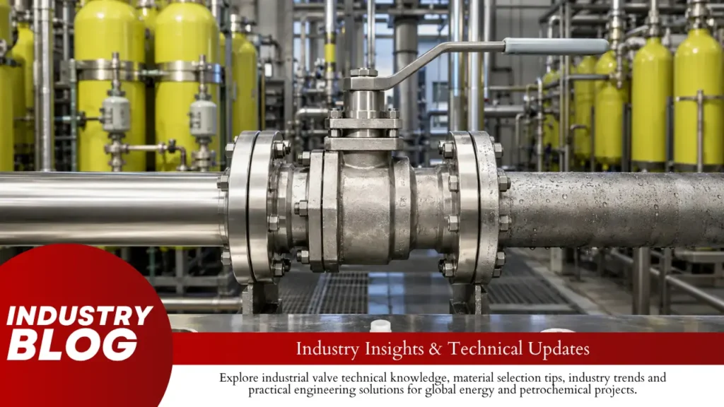
A chlorine ball valve should be specified by moisture condition, chlorine phase, temperature, materials, cavity relief, and stem sealing. Carbon steel may be suitable for controlled dry chlorine, but water can cause rapid local corrosion. Titanium may work in proven wet chlorine but must not contact dry chlorine. Liquid chlorine also needs a reliable pressure-relief path wherever liquid can become trapped. Chlorine has a molecular weight of 70.9, a boiling point of about −29°F (−34°C), and a vapor pressure of about 6.8 atm, or 690 kPa absolute, near room temperature. Chlorine gas is about 2.47 times as dense as air. These properties explain why liquid chlorine can flash quickly after a pressure drop and why leaked gas can collect in low areas.[1] At 20°C, liquid chlorine has a density of about 1.4085 kg/L. If one liter fully vaporizes at about 20°C and atmospheric pressure, it can produce roughly 470–480 liters of chlorine gas. A small liquid leak can therefore release a much larger gas volume.[2] This article covers industrial elemental chlorine, Cl2, in gaseous or liquid form. It does not cover sodium hypochlorite, chlorine dioxide, hydrochloric acid, or other chlorine-containing liquids. NIOSH lists a 15-minute ceiling exposure recommendation of 0.5 ppm, equal to about 1.45 mg/m³, and an immediately dangerous to life or health concentration of 10 ppm. NIOSH also gives a conversion of 1 ppm chlorine to approximately 2.90 mg/m³. These worker-exposure values show why small external leaks require attention, but they are not valve leakage acceptance limits.[3] Define the Service A request that says only “2-inch Class 300 ball valve for chlorine” is incomplete. Give the manufacturer the actual process conditions. Item Information required Chlorine condition Dry, moist, wet, or able to change between these conditions Phase Gas, liquid, saturated gas, flashing liquid, or possible two-phase flow Water content Normal, maximum, alarm, shutdown, and restart values Water unit ppm by mass, ppm by volume, mg/kg, or another defined basis Pressure Normal, maximum operating, design, differential, and blocked-in pressure Temperature Normal, maximum upset, minimum process, flashing, and ambient temperatures Flow Normal and maximum flow, Cv or Kv, and expected pressure drop Impurities Hydrogen chloride, oxygen, hydrogen, organics, salts, solids, and nitrogen trichloride Valve duty Isolation, emergency shutdown, transfer, vent, drain, sampling, or control Operating frequency Expected cycles per day, month, or year Fail action Open, closed, stay-put, or a defined sequence involving several valves Leakage requirement Seat, stem, body-joint, and fugitive-emission acceptance criteria Preparation Cleaning, drying, testing, packaging, storage, and commissioning requirements Include abnormal conditions. A failed dryer, wet purge gas, open drain, leaking heat exchanger, humid air, or incomplete drying after a water test can change a dry-chlorine valve into wet service. Separate Dry and Wet Chlorine Water changes how chlorine attacks metal. When water forms a film on the surface, chlorine can create a corrosive acidic liquid. Damage may begin at the seat pocket, packing box, gasket edge, thread, relief hole, or another narrow space before general body-wall loss becomes visible. A moisture level of 150 ppm by mass appears in older dry-chlorine specifications. It should not be used as a universal dividing line. The Chlorine Institute states that acceptable dry-chlorine criteria must be set for each facility because pressure, temperature, materials, sampling, and operating conditions affect corrosion. Its Pamphlet 100 states that there is no single dryness value that applies across all chlorine production and use conditions.[4] A project may use 150 ppm, a lower value, or another qualified limit. The specification should state where the limit came from, where it is measured, how accurate the analyzer is, and how long an abnormal reading may continue before the system isolates. Condition Main risk Selection response Controlled dry chlorine Water ingress, contamination, high temperature, and expansion cooling Use qualified dry-service materials with strict moisture control Moist or saturated chlorine gas Condensation and local wet corrosion Check the coldest surface and possible liquid-film formation Chlorine mixed with water Acidic liquid, crevice attack, permeation, and liner damage Complete a separate wet-service material review Moist chlorine gas and chlorine in an aqueous liquid are not identical services. Do not use one general compatibility chart for both. Measure Moisture Correctly A moisture analyzer is useful only when its sample represents the condition near the valve. State: Whether the result is based on mass or volume Whether the sample comes from gas or liquid The distance between the sample point and the valve The temperature of the sample line Whether the sample line can collect condensate The analyzer range, accuracy, and response time The alarm and shutdown values The required response after analyzer failure The reading required before chlorine enters the system A practical data sheet should include at least four moisture values: normal operating level, alarm level, shutdown level, and restart limit. It should also state whether each value is ppm by mass or ppm by volume. A number such as “150 ppm” is incomplete without the measurement basis. The Chlorine Institute covers sensing lines and instrumentation for wet chlorine gas, dry chlorine gas, and dry liquid chlorine in Pamphlet 165. It also advises facilities to consider continuous analysis for impurities such as water, hydrogen, and nitrogen trichloride.[5] Euro Chlor publishes a separate analytical method for measuring moisture in dry gaseous chlorine. This supports treating sampling, sample-line condition, and measurement method as part of the valve material-control plan.[6] A dry reading at the main header does not prove that a dead leg, low point, closed branch, or valve cavity is dry. Check the parts that are slowest to dry and most likely to collect water. Review Every Operating State Check the valve during normal operation and during: Initial commissioning Start-up after maintenance Normal shutdown Emergency isolation Rapid depressurization Water testing and final drying Inert-gas purging Loss of the chlorine dryer Reverse flow from another system Atmospheric exposure during maintenance Dry nitrogen does not attack titanium. The danger appears when chlorine remains inside the valve and becomes dry during purging, or when dry chlorine enters after the purge. An analyzer failure
How to Select a Ball Valve for Seawater Injection | Duplex Grades, PREN, Galvanic Corrosion
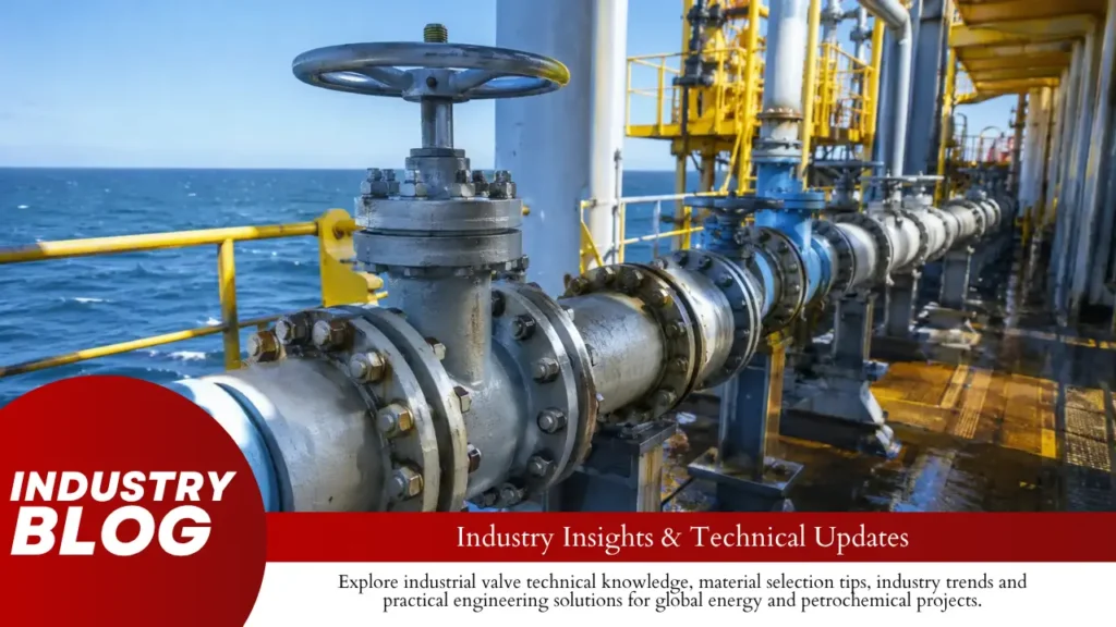
For many raw, aerated or chlorinated seawater injection systems, start by evaluating a trunnion-mounted ball valve with UNS S32750 or S32760 wetted metal parts. Duplex 2205 may be suitable for cooler, treated and deoxygenated water, but only after checking temperature, dissolved oxygen, chlorine, shutdown time and valve crevices. PREN helps compare alloy chemistry; it does not prove that a complete valve will resist seawater. Select the valve as one assembly. Check the body, ball, stem, seats, springs, drain plugs, coatings and fasteners. The valve must also withstand the maximum closing differential pressure, release trapped cavity pressure, tolerate the expected particles and provide enough breakaway torque after a long period without movement. Define the Water Average ocean water contains about 35 parts per thousand, or 3.5%, dissolved salts.[1] Typical seawater also contains about 19,000 mg/L of chloride.[2] Open-ocean surface water is commonly around pH 8.1, while oxygenated surface water may contain dissolved oxygen near 8 mg/L, depending on temperature, salinity and biological activity.[3][4] These values explain why ordinary stainless steel may struggle in seawater, but they are not design limits. Use the actual water analysis from the project. ISO 21457 includes utility and injection systems in its material-selection scope and requires the relevant corrosion mechanisms and operating conditions to be reviewed.[5] Input Information required Why it matters Water type Raw, filtered, chlorinated or deoxygenated seawater Treatment changes oxygen, solids and chemical exposure. Chloride Normal and maximum concentration Higher chloride increases pitting and crevice-corrosion risk. Temperature Normal, design and shutdown maximum Localized corrosion resistance usually falls as temperature rises. Dissolved oxygen Normal value and treatment-failure value Aerated water is usually more severe than properly deoxygenated water. Chlorination Chemical, normal residual, peak dose and duration Oxidizing chemicals can increase localized corrosion. Solids Maximum size, hardness and concentration Sand and debris can cut seats or damage ball coatings. Pressure Normal, design, pump shut-in, surge and reverse pressure The largest load may occur during closing or a pump trip. Shutdown Maximum stagnant period and preservation method Water can remain behind the seats after the main line is drained. Design life Required service life and inspection interval Some offshore projects target 20–30 years, so difficult-to-replace valves need a larger margin. Use the most severe condition that can actually occur. Normal water may be cool and deoxygenated, while startup water is aerated and shutdown water becomes warm and stagnant. Do not replace these conditions with a yearly average. Check the Valve Location A seawater injection system does not have one uniform service condition. The valve location changes the main risks. Intake valves may see aerated water, marine growth, sand, shells and chlorine. Filtered-water valves see fewer large particles, but oxygen and chlorine may remain. Deoxygenated-water valves normally see lower oxygen, but must also survive treatment failure, commissioning and air entry during shutdown. Pump-discharge valves usually see treated water but face higher pressure, closing load and surge. State the real filter performance. A 10 μm filter, a 50 μm filter and a 100 μm filter do not create the same seat duty. Particle hardness also matters: a soft 50 μm deposit and a hard 50 μm mineral particle can affect the seat differently. Include the largest particle expected during filter bypass or failure. For high-pressure duties, review the service against a duplex or super duplex trunnion ball valve. The trunnion ball valve selection guide also explains how pressure class, material and end connection work together. Choose the Alloy Material Representative PREN range When it may be considered Main limit 316L About 23–26 Freshwater or controlled low-chloride water Usually has too little localized-corrosion margin for raw or chlorinated seawater valve crevices. Duplex 2205 About 33–36 Cooler, treated, deoxygenated and drainable systems Needs close review of oxygen upsets, chlorine, stagnant periods and seat-pocket crevices. UNS S32750 About 40–43 Raw, aerated, chlorinated or difficult-to-drain seawater Not automatically suitable for every temperature or oxidant level. UNS S32760 Usually above 40 Projects that specify this grade or have qualified service experience The result depends on whether the project uses PREN or a tungsten-containing PREW formula. Higher alloy Depends on grade Warm chlorinated water, severe crevices or previous super duplex failures Higher price does not remove the need for good valve design and manufacturing. “2205” is a common family name linked to UNS S31803 and UNS S32205. State the exact UNS number, ASTM grade and product form in the purchase order. Do not rely on the name “2205” alone. S32750 and S32760 are both super duplex grades, but their chemical limits and alloy additions differ. S32760 commonly includes copper and tungsten. Any substitution must include a review of chemistry, mechanical properties, welding, heat treatment and corrosion testing. For more detail on body and trim options, see the guide to ball valve material selection. Use PREN Carefully PREN means Pitting Resistance Equivalent Number. A common formula is: PREN = %Cr + 3.3 × %Mo + 16 × %N PREN compares the chromium, molybdenum and nitrogen content of stainless steels. It is useful for screening alloy chemistry, but duplex performance also depends on heat treatment, phase balance, surface condition and valve crevices.[6] Example material Cr Mo N Calculated PREN 316L example 17.0% 2.2% 0.05% About 25.1 2205 example 22.0% 3.2% 0.18% About 35.4 S32750 example 25.0% 4.0% 0.27% About 42.5 These are example calculations, not guaranteed values for every heat. Calculate PREN from the actual material certificate for each main wetted part. The body, ball and stem may come from three different heats and may therefore have three different calculated values. PREN does not show: Water temperature or chlorine dose Crevice size and stagnant-water exposure Heat-treatment quality Harmful intermetallic phases Surface roughness or iron contamination Galvanic contact with another metal Particle or coating damage A PREN of 42 does not mean that a valve is safe up to 42°C. PREN is not a temperature limit. Even a 10–20°C increase in water temperature can change localized-corrosion behavior, especially where warm water is trapped inside a seat pocket or body cavity. Some specifications use a PREW formula
How to Choose a Ball Valve for Wet CO2 Pipelines | Carbonic Acid Corrosion, Overlay, Trim Materials
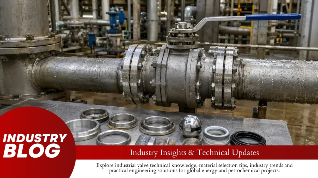
Choose a wet CO₂ ball valve by checking water, impurities, pressure, temperature and operating conditions—not CO₂ percentage alone. Carbon steel may work when water exposure is limited and the expected corrosion loss is acceptable. Continuous water, chlorides, oxygen, acidic impurities, sand or long service without inspection may require CRA overlay, corrosion-resistant trim, hard-coated sealing surfaces and seals tested for rapid CO₂ decompression. Check the complete valve rather than only the pressure-containing body. The ball, stem, seat rings, springs, bearings, body cavity, drain holes and elastomer seals can fail before the main body wall becomes too thin. CARILO’s API 6D forged ball valve guide explains the main full-bore, reduced-bore and fire-safe construction options used in pipeline service. Start with the Water Dry CO₂ is much less corrosive to carbon steel than CO₂ mixed with liquid water. Once CO₂ dissolves in water, it changes the water chemistry and supports corrosion reactions at the steel surface.[1] A simplified reaction is: CO₂(aq) + H₂O ⇌ H₂CO₃ The real water phase is more complex. It may contain bicarbonate, carbonate, dissolved iron, chlorides, oxygen, H₂S, organic acids, treatment chemicals and solid particles. These substances can change the corrosion rate and the type of damage. A valve can be harder to protect than straight pipe because water may remain in: The body cavity Seat pockets Stem and trunnion bores Spring pockets Drain and vent passages Seal grooves The rear side of seat rings These areas may remain wet after the main pipeline has drained. A closed valve cavity may also receive little or no fresh corrosion inhibitor. Iron carbonate may form on carbon steel and slow the average corrosion rate. It is not a permanent protective coating. Flow, sand, low pH and valve movement can damage it. Tests on X65 steel have also found localized corrosion beneath developing and apparently complete iron-carbonate layers.[2] A low average corrosion rate therefore does not prove that a seat pocket, sealing surface or narrow drain passage is safe. Define the CO2 Service Wet CO₂ pipelines do not all carry the same fluid. The source of the CO₂ changes the impurities, water conditions and operating risks. Service Common conditions Valve areas at risk Oil and gas production Produced water, chlorides, H₂S, organic acids, sand and corrosion inhibitor Seat pockets, ball surface, springs, drains and bearings Wet CO₂ gas Shutdown condensation, low-point water and intermittent wetting Lower body cavity, seat pockets and stem bore CCS pipeline Water excursions, oxygen, NOx, SOx, rapid pressure reduction and phase changes All wetted surfaces, elastomers, vents and relief passages For CCS service, define both normal fluid composition and possible off-specification conditions. DNV-RP-F104 covers CO₂ properties, safety, materials, design, construction and operation as connected parts of a CO₂ pipeline system.[3] Water, oxygen and nitrogen or sulfur oxides can interact and create more severe corrosion than pure CO₂ and clean water alone.[4] A CCS specification should state: Normal impurity limits Maximum water content Possible off-specification composition Maximum off-specification duration Water-monitoring method Shutdown and restart requirements Collect the Design Data Use operating ranges rather than one normal pressure and temperature. Required data Why it matters Minimum and maximum pressure Body rating, seat load, phase behavior and decompression Full temperature range Corrosion, toughness, seat strength and actuator output CO₂ concentration Gas-phase partial pressure and fluid behavior Water content Dew point and condensation risk Free-water rate How long and how much of the valve remains wet Chloride concentration Water conductivity, pitting and crevice corrosion Water pH and alkalinity Carbon steel corrosion and iron-carbonate formation H₂S concentration and partial pressure Sour-service cracking risk Oxygen, NOx and SOx Oxidizing and mixed-acid corrosion Organic acids Carbon steel corrosion and deposit stability Sand concentration and particle size Ball coating, seats, bearings and drain blockage Flow rate and pressure drop Erosion, turbulence and local cooling Corrosion inhibitor Whether protected carbon steel is practical Blowdown rate Low temperature and rapid gas decompression Operating cycles Seat, coating, bearing and actuator life The data should cover normal operation, start-up, low flow, shutdown, blocked-in conditions, cleaning, water carryover and emergency depressurization. Calculate CO2 Partial Pressure For a simple gas mixture, approximate CO₂ partial pressure can be calculated by multiplying absolute pressure by the CO₂ mole fraction. Total pressure CO₂ content Approximate CO₂ partial pressure 50 bar absolute 10 mol% 5 bar 80 bar absolute 20 mol% 16 bar 100 bar absolute 20 mol% 20 bar 120 bar absolute 50 mol% 60 bar For example: 100 bar × 0.20 = 20 bar CO₂ partial pressure This calculation is useful for initial gas-phase screening. It does not show whether water is present, how much of the valve is wet or whether the water contains chlorides, oxygen or acids. Dense-phase CO₂ requires a suitable thermodynamic model. Fugacity, water solubility, phase changes and impurity distribution cannot be fully described by simple multiplication. Assess the Corrosion Risk Do not judge valve life from one average corrosion rate. The review should include: Uniform corrosion during normal operation Localized corrosion during shutdown Under-deposit corrosion beneath sand or scale Corrosion during inhibitor failure Attack at CRA-overlay edges Crevice corrosion behind seats and seals Erosion-corrosion caused by particles or high velocity The following table shows calculated uniform wall loss. It does not include pitting, crevice corrosion, erosion or abnormal operation. Average corrosion rate 10-year loss 20-year loss 30-year loss 0.05 mm/year 0.5 mm 1.0 mm 1.5 mm 0.10 mm/year 1.0 mm 2.0 mm 3.0 mm 0.20 mm/year 2.0 mm 4.0 mm 6.0 mm 0.50 mm/year 5.0 mm 10.0 mm 15.0 mm A rate of 0.10 mm/year appears small, but it produces 2.0 mm of uniform loss over 20 years. A local pit can grow faster than this average value and may damage a seat pocket before the main body wall reaches its minimum thickness. Assess corrosion over the full temperature range. The highest rate may occur at an intermediate temperature where reactions are active but the iron-carbonate layer is still thin or unstable. A straight-pipe corrosion result should not be copied directly to every valve surface. A valve has
How Long Should a Cryogenic Ball Valve Extension Bonnet Be? | Insulation Thickness, Packing Temperature, Clearance
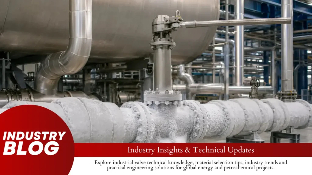
A cryogenic ball valve extension bonnet has no fixed length that works for every installation. It must keep the stem packing above the finished insulation, within the approved temperature range of the complete stem-sealing system, and accessible for inspection and replacement. For early layout, a non-cold-box ball valve may have a centerline-to-stuffing-box height near 200–350 mm. A cold-box valve may require 400–800 mm or more. These are planning ranges, not standard minimum dimensions. The final height must be no less than the largest of three values: the project or standard minimum, the height required to clear the insulation, and the height required to keep the packing warm enough. The selected design must also pass checks for stem twist, actuator weight, installation angle and thermal movement. What Sets the Length? Nominal valve size is only one input. Two DN 50 valves can have different body diameters, pressure classes, stem sizes and packing locations. Installation Main Requirement Insulated cryogenic line Body radius, insulation thickness and maintenance space Valve inside a cold box Centerline-to-wall distance and outside access Inclined valve stem Liquid position inside the bonnet and approved stem angle Large actuator or gearbox Stem twist, bonnet bending load and support Valve exposed to cold vapor Packing, actuator and accessory temperatures Custom long extension Thermal evidence and mechanical strength CARILO supplies forged cryogenic ball valves for low-temperature applications. The exact bonnet dimension should still be confirmed from the project conditions and approved drawing. Compare Fluid Temperatures The fluid temperature affects the bonnet temperature gradient, but it does not directly give the required length. The figures below are rounded reference temperatures at or near normal boiling pressure. Cryogenic Fluid Approximate Temperature Selection Note LNG About −161°C to −162°C Actual temperature varies with LNG composition and pressure Liquid oxygen About −183°C Also requires oxygen-compatible materials and cleanliness Liquid argon About −186°C Close to the lower part of the ISO 28921 temperature range Liquid nitrogen About −196°C Near the lower limit of ISO 28921-1 Liquid hydrogen About −253°C Outside the −196°C scope of ISO 28921-1 U.S. Department of Energy LNG research uses temperatures near −161°C for cryogenic LNG conditions.[1] Normal boiling-point data for oxygen, argon, nitrogen and hydrogen are available from the NIST Chemistry WebBook and NIST reference tables.[2][3][4][5] Define the Dimension “Bonnet length” can describe several different dimensions: Body surface to packing gland Body surface to actuator mounting face Valve centerline to top of stuffing box Fabricated extension-tube length Overall valve height These values cannot be compared directly. A supplier quoting a 300 mm tube may place the packing lower than another supplier quoting a 300 mm centerline-to-stuffing-box height. For project comparison, a practical reference is the distance from the valve centerline to the top of the stuffing box. The stuffing box is the metal chamber that holds the packing rings. The packing gland presses the rings against the stem and chamber wall. The actuator mounting face is above the packing and should not be used as a substitute for the packing position. Ask the manufacturer to show these points on the drawing: Valve centerline Maximum body radius Bottom and top of the packing set Packing gland and gland bolts Top of the stuffing box Actuator mounting face Extension inside and outside diameters Drain, vent and seat-injection connections Overall height Large trunnion-mounted valves often have wider bodies, larger stems and more external fittings than floating valves. Their insulation envelope should come from the actual drawing. See the trunnion-mounted ball valve selection guide for related construction details. Check the Standards ISO 28921-1:2022 covers the design, dimensions, materials, fabrication and production testing of metallic isolation valves used from −50°C down to −196°C. It includes ball and plug valves, but it does not replace project-specific insulation and clearance checks.[6] ISO 28921-2:2015 is the current published standard for low-temperature type testing. It verifies a defined valve design under stated test conditions. It does not automatically qualify every bonnet length, stem diameter, packing system or installation angle.[7] ISO 28921-2 also states that an actuator is not evaluated unless it is an integral part of the valve. A valve test report does not automatically qualify a separately selected actuator, positioner or solenoid. A second edition of ISO 28921-2 is under development and is intended to replace the 2015 edition. Purchase documents should therefore state the exact published edition required by the project.[8] ANSI/MSS SP-134-2025 covers cryogenic valves and includes requirements for body and bonnet extensions.[9] BS 6364:1984 still appears in older catalogues, but BSI lists it as withdrawn from July 2021. It should not be presented as the current standard for a new project unless the contract specifically requires it.[10] ASME B16.34 covers pressure-temperature ratings, materials, dimensions, examination, testing and marking for applicable industrial valves. ASME lists B16.34-2025 as the current edition.[11] ASME B31.3 covers process piping in petroleum, chemical, hydrogen and cryogenic plants. It applies to the surrounding piping, supports, movement, fabrication, examination and testing rather than directly calculating the bonnet length.[12] A standard minimum does not prove that the actual valve: Clears the finished insulation Keeps the packing within its approved temperature range Fits through the cold-box wall Leaves enough tool space Supports the selected actuator Has acceptable stem twist Measure the Insulation The packing gland should normally remain outside the permanent cryogenic insulation. Use the complete finished insulation thickness, including: Main insulation material Vapor-retarder layers Outer vapor barrier Sealant and overlap areas Metal or polymer jacket Removable cover Fire-protection layer where required Installation tolerance Do not add an assumed 10 or 20 mm without checking the project insulation drawing. Different systems use different jackets, joints and removable covers. Measure from the valve body, not from the connected pipe. For example: Pipe outside radius: 30 mm Valve body radius: 85 mm Finished insulation thickness: 100 mm If the calculation starts from the pipe radius, the finished insulation boundary will be shown 55 mm too low. The gland may then be partly covered after installation. Use the highest body surface that must remain insulated. Include body bolts, drain valves,
Can Ball Valves Be Used in Vacuum Service? | Seat Sealing Direction, Outgassing, Leakage Testing
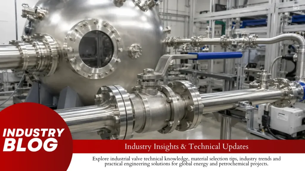
Yes, ball valves can be used in vacuum service, but a normal pressure rating does not prove that a valve will hold vacuum. The valve must seal in the installed pressure direction, limit air entry through the stem and body joints, use materials with an acceptable gas load, and pass separate seat and external leakage tests. Clean soft-seated ball valves are often suitable for rough and medium vacuum. High vacuum, repeated bakeout, frequent cycling, particles or contamination-sensitive processes may require a specially built vacuum valve. Selection should be based on absolute pressure, effective pumping speed, gas type, temperature, seat design and measured leak rate—not only on the words “vacuum rated” or “bubble-tight.” Vacuum Range Vacuum is measured as absolute pressure. A lower absolute pressure means a deeper vacuum. The ranges below are common engineering descriptions, although the exact boundaries may differ slightly between industries. Vacuum range Approximate absolute pressure Ball valve use Rough vacuum 1,000 to 1 mbar Many industrial ball valves can work after leakage and material checks Medium vacuum 1 to 10−3 mbar Clean, vacuum-tested soft-seated valves are often suitable High vacuum 10−3 to 10−7 mbar Low-gas-load materials, controlled cleaning and helium testing are normally required Ultra-high vacuum Below 10−7 mbar Ordinary industrial ball valves are rarely the first choice These ranges are not fixed valve limits. A clean, purpose-built valve may work at a lower pressure than expected. A contaminated valve with weak stem packing may cause problems even in rough vacuum. ISO 3529-1 provides the general vocabulary used in vacuum technology.[1] With one port near atmospheric pressure and the other near zero absolute pressure, the differential pressure is about 1.013 bar at standard atmospheric conditions. Most industrial valve bodies can withstand this load. The harder task is controlling very small gas flows through the seats, stem seals, body joints and non-metallic materials. Pressure Rating A Class 150, Class 600, PN16 or PN40 rating mainly describes the valve’s positive-pressure capability at a stated temperature. It does not prove that the valve can maintain a low vacuum pressure. A normal pressure rating does not confirm: Leakage across the closed ball Outside air entering around the stem Leakage through body gaskets Gas passing through elastomer seals Outgassing from seats, grease or cleaning residue Leakage after heating or repeated operation ISO 5208 covers pressure-boundary and closure-tightness testing for industrial metallic valves.[2] These tests remain useful, but a water or compressed-gas pressure test is not the same as a vacuum helium test. ASME B16.34 covers pressure-temperature ratings, materials, dimensions, testing and marking for several forms of industrial valves.[3] Vacuum testing should be added to these mechanical requirements, not used instead of them. Positive-pressure strength still matters. A vacuum line may see nitrogen purging, cleaning pressure, pump backpressure or an upstream process fault. Liquid trapped inside a closed valve cavity can also produce high pressure when heated. Carilo’s API 6D ball valve factory acceptance test guide explains common shell, seat and functional checks. API Specification 6D defines manufacturing and testing requirements for pipeline valves, but it is not a complete high-vacuum qualification standard.[4] Sealing Direction The direction of the pressure difference can change how tightly a ball valve seals. This is especially important in floating ball valves. When one port is at atmospheric pressure and the other is under vacuum, pressure pushes a floating ball toward the vacuum-side seat. That seat normally carries most of the pressure-assisted sealing load. The two seats may use the same material but still perform differently because of: Different initial compression Machining tolerances Relief grooves behind one seat A vent hole in the ball Different cavity passages Unequal seat support A valve may pass the required leakage limit in one direction but fail after the pressure direction is reversed. The test certificate must identify the vacuum port, higher-pressure port and test direction. Before installation, confirm: Whether the ball is floating or trunnion mounted Which port faces the vacuum chamber Which port normally sees the higher pressure Whether the seats are mechanically symmetrical Where the ball and cavity vents are located Which direction was used during factory testing Whether pressure can reverse during operation Do not select the vacuum direction only from an external flow arrow. Ask for a sectional drawing that shows the ball, seats and vent passages in the closed position. Low Pressure Difference A floating ball receives strong pressure-assisted sealing when one side is at atmospheric pressure and the other side is under vacuum. It receives much less help when both sides are already at low pressure. Pressure condition Approximate differential pressure Effect on floating ball Atmosphere versus 10−3 mbar About 1,013 mbar Strong pressure-assisted seat loading 10−2 versus 10−4 mbar 0.0099 mbar Very little pressure-assisted seat loading The two examples differ in pressure differential by roughly 100,000 times. This is why a valve that seals well between atmosphere and vacuum may perform differently when both ports are already evacuated. At low differential pressure, sealing depends more on: Initial seat preload Seat elasticity Ball roundness Ball surface finish Seat alignment Spring loading Correct actuator stops Pressure Force and Valve Size The force pushing a floating ball toward the lower-pressure seat increases with the projected area exposed to the pressure difference. The simplified relationship is: Force = pressure difference × projected area The following values use a differential pressure of 1 bar and a circular projected area. They are theoretical examples, not actual actuator-torque or seat-contact values. Projected diameter Projected area Force at 1 bar differential 50 mm About 1,963 mm² About 196 N 100 mm About 7,854 mm² About 785 N 150 mm About 17,671 mm² About 1,767 N Doubling the projected diameter increases the area and pressure force by about four times. Larger floating ball valves can therefore develop much higher seat loading, operating torque and polymer deformation than smaller valves. The actual load depends on the ball geometry, port size, seat diameter, body clearances and friction. These figures should be used to understand the scale of the force, not to size an
Ball Valves for Thermal Oil Systems | High Temperature, Fire Safety, Stem Sealing

A thermal-oil ball valve should be selected from the maximum continuous temperature, pressure at that temperature, shutoff differential pressure, oil condition and operating frequency. For clean oil within a verified soft-seat rating, a reinforced polymer seat may provide tight shutoff and low torque. At about 300°C or higher, a metal-seated valve should normally be checked first unless the manufacturer can prove that a complete polymer-seated valve is suitable for the stated temperature and pressure. A valve that passes a room-temperature water test can still leak, seize or require excessive torque after repeated heating and cooling. Before purchase, obtain the valve pressure-temperature chart, seat-leakage limit, hot torque data, cavity-relief arrangement and a list of all nonmetallic parts. Operating Data Start with the exact heat-transfer-fluid name. Mineral oil, synthetic aromatic fluid, silicone fluid and food-grade thermal oil can have different viscosity, thermal stability and fire properties. Record four temperatures: Normal operating temperature: the temperature during most operating hours. Maximum continuous temperature: the highest temperature expected for long periods. Maximum upset temperature: the highest short-term temperature during stopped flow or another fault. Minimum startup temperature: the lowest temperature at which the pump and valve may operate. Condition Example value Main effect on the valve Normal temperature 280°C Seat wear, packing life and normal torque Maximum continuous temperature 320°C Seat creep, gasket relaxation and material strength Upset temperature 330°C for 30 minutes Permanent seal damage or thermal seizure Minimum startup temperature 10°C High oil viscosity, pressure loss and actuator torque Packing-chamber temperature Measured or calculated Stem leakage and packing life Actuator mounting temperature Measured at the bracket Actuator seals, switches, solenoids and cables In this example, the valve may move from 10°C during startup to a 320°C design condition. That is a 310°C temperature change. The ball, seats, body, stem and packing do not all expand by the same amount, so a valve that turns freely when cold may become tight when hot. Cold oil can also be much more viscous than hot oil. Higher viscosity increases pipe resistance, pump discharge pressure and the force needed to move oil through the valve cavity. Use the viscosity curve for the actual fluid at 10°C, not only its value at 280°C. Do not use heater film temperature as the valve temperature. Film temperature is the temperature of the thin oil layer next to a heated surface. A valve normally sees the local bulk temperature, although a valve close to the heater may continue heating after circulation stops. The packing chamber may be cooler than the oil because the valve neck releases heat to the air. Covering the whole neck with insulation can raise the packing and actuator temperature. For heavily insulated valves, ask for the expected temperature at the gland and actuator bracket. Pressure at Temperature A pressure class is not a fixed pressure limit at every temperature. As the body material becomes hotter, its permitted pressure normally falls. ASME B16.34 covers pressure-temperature ratings, materials, dimensions, examination, testing and marking for many flanged, threaded and welding-end valves.[1] Do not specify only: DN100, Class 300, carbon-steel ball valve. State the full condition: Design pressure: 18 bar Design temperature: 320°C Maximum shutoff differential pressure: 12 bar Minimum startup temperature: 10°C The valve body pressure-temperature rating must cover 18 bar at 320°C. Saying that a body is simply “rated for 320°C” is incomplete because pressure and temperature must be checked together. The seat must also hold 12 bar differential pressure at 320°C. The metal body may remain structurally suitable after a polymer seat has already softened, crept or lost sealing force. Valve condition Upstream pressure Downstream pressure Seat differential pressure Valve open during circulation 15 bar 12 bar 3 bar Valve closed, downstream still pressurized 15 bar 5 bar 10 bar Valve closed, downstream depressurized 15 bar 0 bar 15 bar This example shows why normal running differential pressure cannot be used for seat selection. The seat may see only 3 bar while the valve is open but the full 15 bar after the downstream line is drained. Check all credible pressure conditions: Normal pump discharge pressure Maximum pump pressure Pump shutoff pressure Cold-start pressure Static head Expansion-tank or nitrogen pressure Maximum closed-valve differential pressure Pressure trapped inside the body cavity A room-temperature shell or seat test confirms the valve under the stated test conditions. It does not prove long-term hot performance. ISO 5208 defines pressure testing used to check the pressure boundary and closure tightness of metallic valves.[2] Valve Design A floating ball valve uses line pressure to move the ball slightly toward the downstream seat. The design is compact and common in smaller sizes, but seat load and operating torque increase with differential pressure. A forged soft-seated floating ball valve can suit clean thermal oil when temperature, pressure and cycling remain inside the verified seat rating. A trunnion-mounted valve supports the ball at the top and bottom. Spring-loaded seats move toward the ball. This design is often used for larger sizes, higher differential pressure and automated isolation because torque is usually easier to control. The forged trunnion-mounted ball valve provides an example of a supported ball with spring-loaded seat assemblies. Condition Floating ball Trunnion ball Typical application Small and medium isolation valves Medium and large automated valves Ball support Supported mainly by the seats Supported by upper and lower trunnions Pressure effect Pressure pushes the ball onto the downstream seat Pressure and springs move the seats toward the ball Torque at high differential pressure Can rise sharply Usually more predictable Cavity arrangements Usually simpler SPE, DPE and hybrid arrangements are common One-piece valves have fewer body joints but may be difficult to repair. Two-piece valves provide access to the ball and seats. Three-piece valves can allow the center section to be removed while the pipe ends remain installed. Every body joint needs a gasket and enough bolt load. Repeated heating and cooling can relax the gasket or bolts, causing a slow external leak. The quotation should identify the gasket material, bolting grade and tightening method. Bore
Ball Valves for Produced Water Service | Chlorides, Sand, Corrosion-Erosion, Coating Options
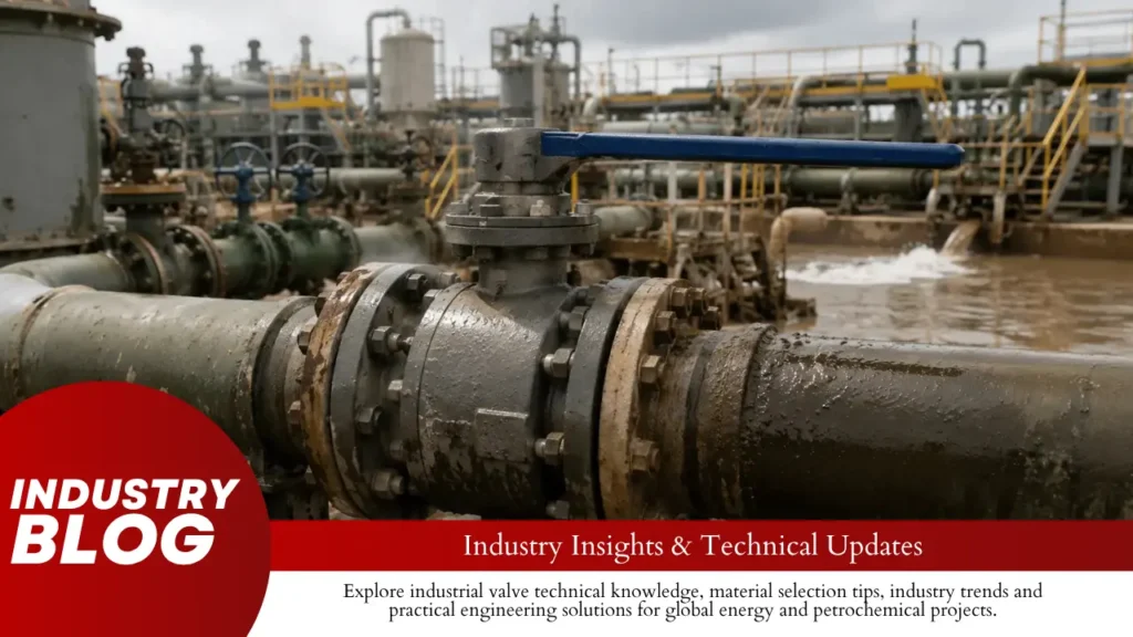
A produced-water ball valve should be selected from five facts: water chemistry, sand and scale, pressure and temperature, operating method, and required leakage rate. Corrosion-resistant alloys or weld overlay protect against chlorides, CO2 and H2S. Metal seats and carbide coatings improve resistance to sand, but they do not stop wear completely.The body, ball, seats, stem, springs, seals and coatings must all suit the same service. Selecting a valve only by pipe size, pressure class or chloride concentration can leave small internal parts unprotected. Data to Collect First The following values should appear in the valve data sheet. The units matter because terms such as “high chloride” or “some sand” are too vague for material selection. Parameter Unit or Data Format Why It Matters Total dissolved solids mg/L Shows overall water salinity Chloride mg/L Affects pitting and crevice-corrosion risk Dissolved oxygen µg/L or ppb Can increase carbon steel corrosion and change stainless steel behaviour CO2 and H2S Dissolved concentration or partial pressure Affects corrosion and sour-service material limits Sand concentration mg/L or mass percentage Affects seat and coating wear Particle size d50, d90 and maximum size in µm Shows whether particles can enter seat clearances or block closure Pressure and temperature bar or MPa; °C Controls pressure rating, material limits and actuator torque Differential pressure bar or MPa Controls local velocity and erosion during operation Operating torque N·m Provides a baseline for detecting sand, scale or internal damage Define the Service Produced-water conditions change with the valve location. State where the valve will be installed before selecting materials. After a separator: water is the main phase, but oil, dissolved gas, fine sand and scale may remain. After water treatment: solids may be lower, while oxygen, bacteria and treatment chemicals may become more important. Water injection: the valve may face high pressure, oxygen entry, mixed-water scale and long shutdowns. Water disposal: deposits may collect during low flow or stagnation. Drain and flushing lines: short periods of very high solids loading may occur. A valve upstream of the separator is exposed to oil, gas, water and slugs. It should be treated as multiphase wellstream service, not produced-water-only service. For main pipeline isolation, bore, seat arrangement, pressure class and testing may need to follow an API 6D forged ball valve design. Check the Water Use a recent water analysis from the actual valve location. Produced-water chemistry can change as water cut rises, injection water reaches the well, treatment chemicals change or separation performance falls. The analysis should include: Chloride and total dissolved solids pH and alkalinity Dissolved oxygen Dissolved CO2 and H2S Gas composition and total pressure Calcium, barium, strontium and sulfate Dissolved iron Oil and grease Suspended solids Corrosion inhibitor Scale inhibitor Biocide Methanol, glycol and other injected chemicals USGS data show that conventional oil and gas produced waters can range from about 5,000 mg/L to more than 350,000 mg/L total dissolved solids. Chloride, sodium and calcium are commonly the main ions.[1] The USGS National Produced Waters Geochemical Database contains records from roughly 18,000 oil, gas and brine wells, showing how widely water chemistry can vary between fields.[2] Check the Sample A laboratory report is useful only when the sample represents the pipeline conditions. CO2 and H2S may escape when pressure is reduced. Oxygen can enter the bottle during sampling. Sand results can change sharply between normal production, startup and separator upset. Record: Sampling point and date Line pressure and temperature Normal, startup or upset operation Whether the sample was depressurized Whether chemical injection was running How the sample was protected from air How quickly unstable components were tested For severe service, compare samples from normal production and credible upset conditions. One clean sample may miss the condition that causes valve failure. TDS and Chloride Total dissolved solids and chloride are not the same measurement. TDS is the approximate total amount of dissolved material. Chloride measures only chloride ions. Two water samples can have the same TDS but different chloride, calcium, sulfate and bicarbonate levels. Chloride affects stainless steel pitting and crevice-corrosion risk. Calcium and bicarbonate affect calcium carbonate scale. Barium, strontium and sulfate affect hard sulfate scale. Dissolved iron may indicate corrosion or iron-containing deposits. Do not use one chloride limit to choose between 316L, duplex, super duplex and nickel alloy. Temperature, oxygen, pH, H2S, deposits, weld quality and stagnant crevices also affect the result. Check the Solids “Sand present” is not enough information. Ask for: Normal and maximum sand concentration d50 and d90 particle size Maximum particle size Particle shape and mineral type Scale particle size Sand-slug duration Startup and flushing conditions d50 is the size below which 50% of the measured particles fall. d90 is the size below which 90% fall. These values show whether a low average result hides a smaller number of large particles. Practical Particle Band Main Concern Possible Valve Damage 10–50 µm Fine particles entering narrow clearances Sand buildup behind seats, higher friction and rising torque 50–250 µm Repeated abrasive impact Seat scratches, coating wear and loss of sealing contact 250 µm–1 mm Large particles reaching the sealing band Deep scratches, seat indentation or incomplete closure Above 1 mm Large sand, scale or debris Immediate blockage or mechanical damage during closing These particle bands are practical review groups, not fixed material-selection limits. Particle shape, velocity, concentration and pressure difference must also be considered. Four solids patterns need different checks: Continuous fine sand: particles can enter the narrow space behind the seat. Short sand slugs: a high concentration can cut the downstream seat in a short time. Large startup particles: one particle may prevent full closure. Detached scale: hard, sharp scale can damage the ball and seat like sand. Quartz is hard enough to scratch polymer seats and poorly supported coatings. Actual wear also depends on particle velocity, size, shape, concentration and impact angle. Check the Flow Provide: Normal and maximum flow rate Actual pipe inside diameter Normal and maximum velocity Gas volume fraction Maximum differential pressure Flow direction and possible reverse flow Operating frequency Time
