
Why Does a DBB Valve Bleed Port Stay Pressurized? | Seat Leakage, Trapped Fluid, Vent Routing
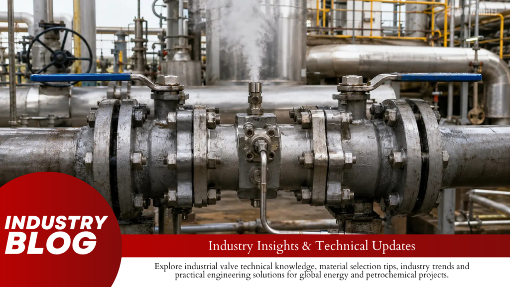
If a DBB valve bleed port stays pressurized after the cavity has been safely vented, compare the cavity pressure with four values: upstream pressure, downstream pressure, vent-header pressure, and valve temperature. Pressure moving toward one pipeline side usually points to a pressure path from that side. Pressure rising above both line pressures points more strongly to trapped-fluid heating. A slow pressure drop points to a restricted bleed path, while pressure stopping near the closed-drain or flare-header pressure points to backpressure. Pressure Behavior Check First 0 → 55 bar while upstream stays near 80 bar Upstream-to-cavity leakage path Cavity remains at 55 bar while current upstream is only 30 bar Old trapped pressure, heating, another pressure source, or gauge error Cavity rises above both upstream and downstream pressure Trapped liquid and thermal expansion 30 bar → 2.2 bar quickly; drain header is 2 bar Drain or vent backpressure 30 bar falls slowly over several minutes Restricted bleed valve or small-bore line Pressure reaches zero, then starts rising again Active pressure source refilling the cavity All pressures and times below are troubleshooting examples. They are not valve ratings or API leakage limits. For the internal position of the seats, ball, body cavity, and bleed connection, see CARILO’s trunnion ball valve internal structure and DBB guide. If Pressure Returns Toward Upstream or Downstream Use a timed pressure record instead of one cavity reading. Time Upstream Downstream Cavity Valve Temperature 10:00 80 bar 0 bar 0 bar 28°C 10:05 80 bar 0 bar 18 bar 28°C 10:10 79 bar 0 bar 31 bar 29°C 10:20 79 bar 0 bar 55 bar 29°C Temperature is almost unchanged, downstream remains at zero, and cavity pressure is moving toward upstream pressure. The first place to investigate is an upstream-to-cavity pressure path. That path is not always the main ball-to-seat contact surface. Check: Ball-to-seat sealing surface Seat ring damage Seat carrier or rear seat seal Debris preventing the seat ring from moving correctly Scratches or erosion on the ball Incorrect actuator or gearbox closed-stop position Other internal passages shown on the valve sectional drawing If the problem appeared immediately after flushing, pigging, commissioning, or pipeline repair, particles or scale should be checked early. If leakage has slowly become worse over months, seat wear, ball damage, corrosion, or erosion becomes more likely. If the problem started after actuator work, confirm the actual closed position before removing the valve. An official API 6D purchasing guideline shows the basic DBB test principle: pressure is applied to the valve ends and leakage toward the body cavity is monitored at the cavity connection.[3] Field pressure trending can use the same pressure-path logic, but it is not an API acceptance test. For external versus internal leak diagnosis, see CARILO’s ball valve field leakage guide. If Cavity Pressure Is Higher Than Both Line Pressures Do not blame the upstream seat first if the cavity pressure is higher than the pressure available upstream. Pressure Point Reading Pipeline pressure when valve closed 60 bar Current upstream pressure 30 bar Current downstream pressure 0 bar Current cavity pressure 55 bar A current 30 bar upstream source cannot, by simple leakage alone, create a 55 bar cavity. The cavity may still contain pressure trapped when the valve closed at about 60 bar. Check the operating sequence. A valve can close while both sides are pressurized, after which one or both pipelines are depressurized. The cavity is separated from the line gauges by the seats, so the pressure between the seats can remain much higher than the current downstream or upstream reading. HSE specifically warns that ball valve cavities can retain trapped pressure and that body vent or drain arrangements must allow the cavity to be properly bled down.[1] If the cavity continues rising above its original trapped pressure, add temperature to the pressure log. If Pressure Rises as the Valve Gets Hotter Compare pressure and temperature at the same time. Time Upstream Downstream Cavity Valve Temperature 07:00 40 bar 0 bar 2 bar 20°C 09:00 40 bar 0 bar 9 bar 27°C 11:00 40 bar 0 bar 24 bar 35°C 13:00 40 bar 0 bar 46 bar 43°C The numbers above show a diagnostic pattern, not a fixed temperature-to-pressure formula. Upstream remains at 40 bar and downstream remains at zero, while cavity pressure rises as the valve becomes hotter. That makes trapped-fluid heating much more important than ordinary upstream seat leakage. Check for: Liquid or condensate trapped in the cavity Direct sunlight Steam tracing left on after shutdown Electric heat tracing Heat conducted from connected piping Hot equipment near the valve Hydrotest or flushing water left inside the cavity Cold process liquid warming toward ambient temperature HSE warns that thermal expansion of liquid trapped between pipeline isolation valves can result in line rupture.[1] API Spec 6D 25th Edition Addendum 3 is more specific for valve design: if liquid trapping is possible, automatic cavity relief is required. For temperatures up to 121°C (250°F), the cavity-relief pressure must not exceed a 33% differential above the valve pressure rating.[4] For example, the 33% figure gives an arithmetic upper value of 133 bar for a 100 bar rating under that stated API condition. It does not mean every 100 bar valve should have its relief device set to 133 bar. Actual design must account for the applicable pressure rating at temperature, relief-device tolerances, backpressure, connected equipment, and the approved manufacturer design. CARILO’s closed ball valve cavity-pressure guide covers trapped liquid and thermal relief in more detail. If Pressure Falls Slowly with the Bleed Open A normal-looking bleed valve handle does not prove that the complete flow path is clear. Small bleed passages can be restricted by: Rust Scale Sand or other process solids Wax in suitable hydrocarbon service Polymer or chemical deposits Ice or frozen condensate Hydrates where the required gas, water, pressure, and temperature conditions exist Debris inside a needle valve A partly closed downstream isolation valve A restricted fitting or small-bore tube HSE warns that plugged small-bore drain lines can
How Large Should the Bleed Connection Be on a DBB Valve? | Depressurization Time, Fluid Phase, Safe Discharge
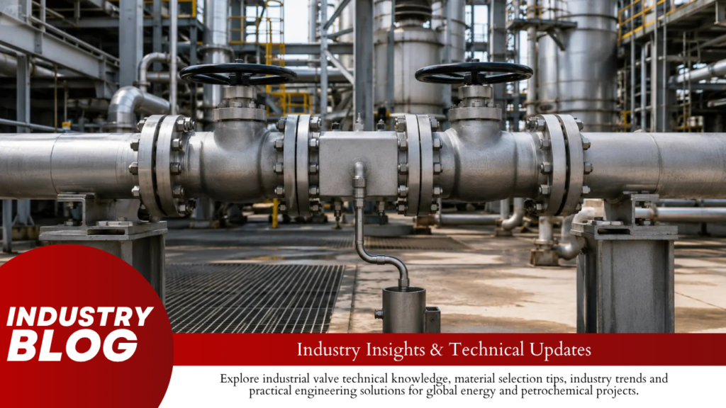
Do not choose a DBB bleed from the main valve NPS alone. Choose the effective flow path that can reduce the trapped cavity from the starting pressure to the required final pressure within the allowed time and against the actual downstream pressure. A 3 mm circular passage has only about 7.1 mm² of area. A 6 mm passage has 28.3 mm², and an 8 mm passage has 50.3 mm². In the 100 L nitrogen example later in this article, increasing the effective bore from 3 mm to 6 mm cuts the simplified bleed-down time from about 216 seconds to 54 seconds. This is why a drawing that says only “3/4-inch NPT bleed” does not give enough information for a serious sizing check. Calculate the Volume You Actually Trap Use the total volume between the two isolation barriers. For a single-body or compact DBB valve, this is mainly the valve body cavity. For two separate block valves, include the pipe spool, fittings, instrument branches, and dead legs between them. Pipe ID Trapped Length Approx. Pipe Volume 25 mm 10 m 4.9 L 50 mm 10 m 19.6 L 75 mm 10 m 44.2 L 100 mm 10 m 78.5 L Doubling the internal diameter from 50 to 100 mm increases the volume of the same 10 m pipe from about 19.6 to 78.5 L. That is four times the trapped volume. Ask the valve manufacturer for the actual cavity volume when bleed-down time is specified. Do not estimate it from NPS. API 6D, 25th Edition Addendum 2 requires a drain or vent connector for the double-seated valves covered by its Section 5.6.1 that seal against the pressure source with the upstream seat, subject to the stated Annex M exception.[1] ISO 14313:2025 supplements API 6D, 25th Edition, for pipeline valves within its scope.[2] Set the Starting Pressure, Final Pressure, and Time Put a measurable requirement in the RFQ, for example: Reduce cavity pressure from 100 barg to 5 barg within 5 minutes. A 5-minute requirement and a 1-minute requirement are very different. If the same amount of fluid must leave, reducing the permitted time from 5 minutes to 1 minute requires about five times the average net discharge rate. Use absolute pressure for gas calculations when the equation requires it. Gauge Pressure Approx. Absolute Pressure 0 barg 1 bara 5 barg 6 bara 20 barg 21 bara 50 barg 51 bara 100 barg 101 bara Do not set a passive bleed target below the receiving pressure. A cavity connected only to a header at 5 barg cannot be passively reduced below 5 barg through that same route. Flow becomes very small as cavity pressure approaches the header pressure. Find the Smallest Passage in the Bleed Path Check the complete route from the valve cavity to the final vent or drain system. A 3/4-inch NPT body tapping may be followed by a 3 mm needle-valve seat, 6 mm-ID tubing, reducers, elbows, a check valve, and 10 m of piping. The smallest restriction and the total line loss can control the bleed time. Equivalent Circular Bore Flow Area Area vs. 3 mm 3 mm 7.1 mm² 1.00× 4 mm 12.6 mm² 1.78× 6 mm 28.3 mm² 4.00× 8 mm 50.3 mm² 7.11× 10 mm 78.5 mm² 11.11× 12 mm 113.1 mm² 16.00× Doubling a circular bore gives four times the area. A 3 mm passage becomes 28.3 mm² when increased to 6 mm; increasing 6 mm to 12 mm raises the area from 28.3 to 113.1 mm². This does not mean actual system flow always increases four times. Valve geometry, tubing friction, gas choking, and downstream pressure still need to be included. Check Cv or Kv Before Comparing Two Bleed Valves Minimum bore is useful for finding physical restrictions and plugging risk, but a needle valve can have much more resistance than a straight circular opening of the same minimum diameter. Ask for the bleed-valve Cv or Kv when bleed-down time matters. Compare like with like. Cv and Kv are different flow-coefficient systems. Approximately: Kv ≈ 0.865 × Cv Cv ≈ 1.156 × Kv A supplier quoting a 3/4-inch connection with Cv 0.15 is not offering the same hydraulic performance as another 3/4-inch arrangement with Cv 0.90. Allow for Deposits in Small Passages Rust, scale, wax, polymer deposits, and solids can reduce a small bleed passage quickly. Take a 3 mm circular bore with an original area of about 7.1 mm². Deposit on Each Wall Remaining Bore Remaining Area Area Loss 0 mm 3 mm 7.1 mm² 0% 0.5 mm 2 mm 3.1 mm² About 56% 1.0 mm 1 mm 0.8 mm² About 89% A passage that was acceptable when clean can therefore become the main restriction after relatively small deposits build up. For dirty service, specify the minimum bore and check whether the bleed assembly can be flushed or cleaned. Calculate Gas Bleed-Down as a Changing Flow Gas inventory changes with pressure, and the mass flow through the bleed also changes as cavity pressure falls. Under a simplified constant-temperature ideal-gas assumption, the fraction of gas mass remaining in a fixed cavity is approximately proportional to absolute pressure. Pressure Approx. Mass Remaining Approx. Mass Removed 100 bara 100% 0% 75 bara 75% 25% 50 bara 50% 50% 25 bara 25% 75% 10 bara 10% 90% 5 bara 5% 95% A 20 L cavity at 101 bara contains, under the same simplified temperature assumption, roughly the same number of gas molecules as about 2,020 L of that gas at 1 bara. This is why a physically small high-pressure gas cavity can still require meaningful bleed capacity. At a large pressure ratio, gas can become choked at the controlling restriction. NASA’s compressible-flow equations show that maximum mass flow occurs when the flow reaches sonic conditions at the minimum area.[3] For an ideal gas with a heat-capacity ratio of 1.4, the critical downstream-to-upstream absolute pressure ratio is about 0.528. If cavity pressure is 51 bara and header pressure is 5 bara, the ratio is about 0.10.
How Long Can Ball Valves Be Stored Before Installation? | Preservation, Flange Covers, Seal Aging
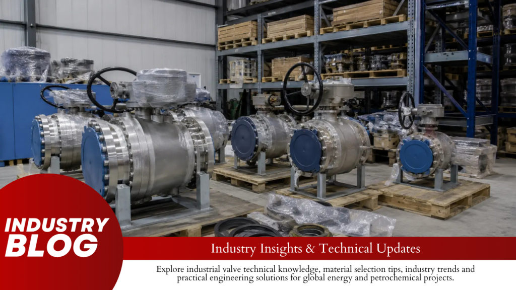
Ball valves do not have one fixed warehouse expiration date. A valve stored correctly for several years may still be suitable for installation, while a valve stored for only a few months may need repair if water, rust or dirt has entered it. Check the preservation record, end covers, bore, seats, flange faces, stem, valve movement and actuator before installation. If standing water, heavy internal corrosion, damaged sealing surfaces or abnormal torque is found, quarantine the valve regardless of its age. Use Condition, Not Age, to Decide What to Do The periods below are practical review points, not manufacturer shelf-life limits. Storage Period Storage Condition Practical Action Under 1 year Dry indoor storage, original protection intact Complete receiving and normal pre-installation checks. 1–3 years Preservation records available Inspect the bore, flange faces, sealing areas, stem and actuator. 3–5 years Controlled long-term storage Use a more detailed inspection and complete any testing required by the OEM or project. Over 5 years Long-term stored equipment Review seal materials, preservation history, spare-parts availability and required testing before acceptance. Any age Water ingress, missing covers, heavy corrosion or contamination Stop installation and inspect the valve. Do not turn 1, 3 or 5 years into automatic rejection limits. API 6D and ASME B16.34 also do not give ball valves a universal warehouse expiration age.[4][5] Use Storage Records to Establish the Real Storage Period Do not calculate storage history from the nameplate year alone. Check these 7 dates where records are available: manufacturing date; factory test or FAT date; shipment date; site receiving date; start of long-term preservation; preservation renewal dates; retesting or repacking dates. A valve manufactured in 2023 may have remained under controlled factory preservation until shipment in 2025. A valve manufactured in 2025 may already have spent a year outside on a construction site. The second valve can require more inspection even though it is newer. For surplus valves or valves transferred from another project, also check whether they were previously opened, pressure tested, dismantled or exposed to process fluid. Record These 8 Items When the Valve Arrives tag number and serial number; nameplate condition; crate and packaging condition; flange covers, plugs and caps; visible transport damage; water or condensation; visible corrosion; valve and actuator position. Take photos of large or expensive valves. If rust, damaged packaging or missing covers are found 2 or 3 years later, the receiving photos provide a useful comparison. If an end cover must be removed during receiving inspection, inspect the valve in a clean area and restore the protection before returning it to storage. Keep Water, Dust and Impact Away from the Valve Store industrial ball valves indoors where practical. Keep them dry, clean, off the floor and protected from dust, chemicals, rain and handling damage. Large valves should remain on their original skid or suitable supports. Do not support the weight of the valve through: the stem; gearbox or actuator; drain or vent fittings; injection fittings; small-bore tubing. Check for condensation even in indoor warehouses. Temperature changes can cause moisture to form on metal surfaces and collect in low areas, body cavities or actuator housings. If the packaging uses desiccant, barrier film or humidity indicators, maintain them according to the preservation instructions. Replace or repair damaged moisture protection instead of leaving torn packaging in place. Outdoor storage needs more frequent inspection. A loose tarpaulin can stop direct rain but still trap humid air around the crate. Leave End Covers On Until the Valve Is Needed Flange covers and port plugs protect the sealing areas from four common construction contaminants: weld slag and metal chips; grinding dust; sand and rust scale; wood, plastic and packaging debris. A hard particle trapped between the ball and seat can cut a soft seat or scratch the ball during the first 90° operation. CARILO’s guide on how to flush a pipeline without damaging ball valve seats explains how weld slag, metal chips and other debris can reach the sealing area. If a flange cover is missing, inspect the bore before installing another cover. Look for: standing water; rust staining; hard particles; damaged seat edges; scratches on visible ball surfaces. Inspect the flange gasket-contact area for pitting, impact marks and deep scratches. Butt-weld valves also need protection over the bore and machined weld bevel. Threaded and socket-weld ends should remain capped or plugged. Return the Ball to the Correct Storage Position A normal on-off ball valve moves approximately 90° from fully open to fully closed. Store it in the position specified by the manufacturer. Do not leave the valve at an arbitrary partly open angle for long-term storage. The partly open position changes seat contact and exposes more of the ball and seat edge to contamination entering through the ports. If the valve is operated during inspection, return it to the specified storage position afterward. Do not cycle a dirty valve repeatedly. Remove or assess the contamination first. Hard particles around the seat can be dragged across the ball during rotation. Check Each Seal Material Separately A ball valve can contain several different sealing materials. They should not be given one common shelf-life number. Seal or Surface Main Storage Concern PTFE / reinforced PTFE seat Long-term deformation, contamination and mechanical damage PEEK or engineered polymer seat Contamination, scratches and incorrect loading NBR / FKM / EPDM O-rings Compound aging, compression and unsuitable environmental exposure Stem packing Compression, contamination and leakage around the stem Graphite Physical damage and contamination Metal seat surfaces Corrosion, scratches and hard debris ISO 2230:2026 gives guidance for storing vulcanized and thermoplastic rubber products and components.[1] It does not provide one expiration period for every sealing material inside an assembled ball valve. Elastomer O-rings can change during long storage because of temperature, chemical exposure, environment and continued compression. The actual compound matters; two O-rings carrying the same broad material name are not automatically identical. PTFE behaves differently from rubber. Under sustained load, PTFE can show time-dependent deformation or cold flow.[2] The effect inside a valve depends on the
How to Flush a Pipeline Without Damaging Ball Valve Seats | Temporary Strainers, Valve Position, Debris Control
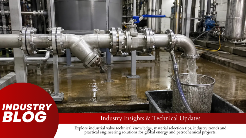
Keep normal on-off ball valves fully open during through-flushing unless the valve manual requires removal or another position. Remove large construction debris before starting the pump, install temporary strainers before sensitive valves and equipment, and measure pressure on both sides of each important strainer. Start at a low, stable pump flow and increase it gradually. Do not use a partly open on-off ball valve to control the flushing rate.This method mainly applies to liquid flushing of new or repaired industrial piping. Steam blowing, high-pressure air blowing, nitrogen blowing, oxygen-service cleaning, and chemical cleaning need separate procedures. How Seats Are Damaged A ball valve seals where the ball contacts the seat. A small scratch across this contact area can create an internal leak path. Damage often happens in this order: Weld slag, metal chips, sand, rust, or other debris enters the valve. The debris stays near the seat, behind a movable seat ring, or inside the body cavity. The valve is operated before the debris has been removed. The particle is pressed between the ball and seat. The seat is cut or dented, or the ball is scratched. Damage Common Cause Result Seat cut Sharp weld slag, wire, or metal chips A narrow internal leak path Seat dent A bolt, stone, thick scale, or other hard object Permanent local deformation Ball scratch A hard particle dragged across the ball during operation Leakage that remains after the particle is removed Seat-edge erosion Dirty high-speed flow through a partly open valve Loss of sealing contact High torque Debris in the cavity, seat pocket, bearing, or sealing area Difficult movement or actuator overload Coating damage Abrasive debris or an unsuitable cleaning chemical Shorter sealing life on a metal-seated valve Seat materials do not fail in the same way: PTFE and reinforced PTFE: Sharp particles can cut the surface or press grooves into it. The sealing performance of a forged soft-seated floating ball valve depends on a smooth ball and an undamaged seat. PEEK and other strong polymers: These materials normally resist wear better than standard PTFE, but hard metal particles can still scratch or indent them. Metal seats: Hard seats handle heat and many particle-containing services better than soft seats, but their lapped surfaces and coatings can still be scored. A metal-seated ball valve still needs a clean pipeline. Elastomer seals: O-rings and other secondary seals may swell, soften, shrink, or harden when exposed to an unsuitable flushing liquid. Valve structure also affects where debris collects. In a floating valve, line pressure moves the ball toward the downstream seat. In a trunnion-mounted valve, the ball is supported while movable seats press against it. Seat pockets, springs, bearings, drains, and the body cavity can hold fine particles even when the main bore looks clean. The floating and trunnion ball valve comparison explains the main structural differences. Check the Valve and Pipeline Data Do not choose the flushing pressure, temperature, flow, valve position, or strainer limit from a general rule. Record the values approved for the actual system. Item What to Confirm Ball valve Tag number, valve type, full or reduced bore, seat material, pressure direction, and required flushing position Flushing liquid Liquid type, temperature, cleanliness, and material compatibility Pressure limit The lowest approved limit among the pipe, valves, hoses, strainers, gaskets, pumps, and instruments Flow requirement The calculated flow or target velocity for each pipe diameter Temporary strainer Screen opening, total area, open area, support, flow direction, and maximum differential pressure Pump Stable operating range, suction pressure, available NPSH, discharge limit, and cavitation signs Acceptance Particle limit, final-screen condition, turbidity, oil, conductivity, chemical residue, or another project limit API Specification 6D covers design, manufacturing, assembly, testing, marking, and documentation requirements for pipeline and piping valves. It does not replace the site flushing procedure or the manual for the installed valve.[1] ASME B16.34 covers pressure-temperature ratings, materials, testing, marking, dimensions, and other requirements for applicable valves. The pressure class shown on a valve is therefore not the only limit that needs to be checked.[2] Where ASME B31.3 applies, the connected process piping also has requirements for design, materials, fabrication, assembly, examination, inspection, and testing.[3] Hydrostatic Testing Is Not Flushing Activity Main Purpose What It Does Not Prove Hydrostatic test Checks the pressure integrity of the piping system It does not prove that the pipe is clean Pipeline flushing Removes loose debris and fluid contamination It does not replace the required pressure test A line can pass a hydrostatic test and still contain rust, weld slag, sand, oil, gasket pieces, or coating flakes. Filling and draining the line may also loosen material from the pipe wall. A flush may therefore be needed after pressure testing. Before testing, confirm whether the valve must be open, closed for an approved seat test, removed, or replaced with a temporary spool. Do not assume that the valve body rating allows the same pressure to be applied across a closed seat. ISO 5208 covers factory examinations and tests used to check the pressure boundary and closure tightness of metallic valves. It does not provide one universal field test for every valve after pipeline flushing.[4] Decide Whether the Valve Should Stay Leaving every valve in the line is not always the safest choice. A temporary full-bore spool may give the debris a clearer path and protect an expensive valve. Condition Practical Action Large amounts of weld slag, scale, stones, or construction debris are expected Remove the valve or install a temporary spool The valve has a V-port, attenuator, small passages, or special control trim Follow the trim-specific procedure and consider removal The valve is reduced-bore and large debris may be present Check the minimum bore and blockage risk before leaving it installed The cleaning liquid may attack the seat, seals, or coating Obtain written material approval or remove the valve The valve cannot be inspected or tested after flushing Use a lower-risk temporary arrangement The line has already been mechanically cleaned and the valve manual permits flushing in place Leave the valve
How Many Spare Parts Should Be Ordered with Actuated Ball Valves? | Commissioning Spares, Two-Year Operation, Critical Parts
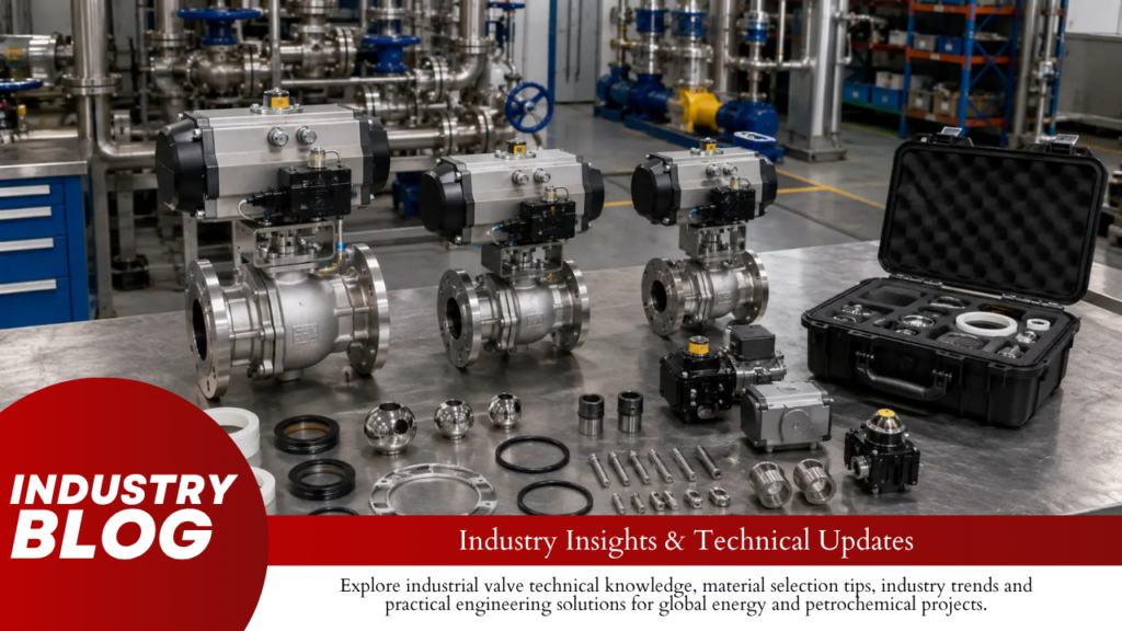
Use 2–5% for commissioning valve and actuator repair kits and 5–10% for two-year operating stock when no plant history is available. Calculate each interchangeable equipment group separately, keep at least one repair kit per group, and keep at least two complete solenoid valves per model. Do not use a percentage for complete actuators or complete valves. Order one only for selected critical groups when repair or supplier delivery would exceed the allowed shutdown time.Commissioning stock and two-year stock should be listed separately. If unused commissioning parts can be transferred to the maintenance warehouse, subtract them before placing the next order. What to Order Spare part Commissioning stock Two-year stock Minimum quantity Valve seat-and-seal kit 2–5% 5–10% 1 per interchangeable group Stem seal kit Only when not included in the main kit Match the planned maintenance work 1 per unique packing design where needed Complete valve overhaul kit Selected valves only Match the planned overhaul quantity 1 for selected critical groups Pneumatic actuator seal kit 2–5% 5–10% 1 per actuator group Hydraulic actuator seal kit 1 per group Planned use plus lead-time stock 1 per actuator group Complete solenoid valve 2 per model or 2–5% 5–10% 2 per model Solenoid coil 2 per model and voltage 5–10% 2 per model and voltage Limit switch box 1 per model 1 per model Add 1 for critical or remote service Proximity sensor 2 per model and output type 2 per model and output type 2 per model Filter-regulator 1 per model or about 2% 2–5% 1 per model Pressure gauge 2 per range and connection 5–10% 2 per range Positioner 1 per model and protocol 1 per compatible group Add 1 for critical, remote or long-lead groups Electric actuator module Selected modules only Based on lead time and failure effect 1 when immediate replacement is required Complete configured actuator Critical groups only 1 per selected critical group Risk-based Complete actuated valve Rarely required 1 for selected critical groups Risk-based The two-year percentages are totals for the full two-year stock package. Do not multiply them by two again. These percentages are purchasing allowances, not API, ISO or IEC requirements. API 6D covers valves within its stated scope, while API 6DX covers actuator sizing, mechanical integrity and mounting kits used with valves within its scope. Neither provides one spare-parts percentage for every project.[1][2] Convert Percentages into Quantities Units in one interchangeable group Commissioning kits Two-year kits 1–10 1 1 11–25 1–2 1–3 26–50 1–3 2–5 51–100 2–5 3–10 101–200 3–10 6–20 Use the lower end for clean, low-cycle service with fast local supply. Use the upper end for dirty service, special seal materials, frequent cycling, remote sites or long delivery. Do not count a stem seal kit, seat-and-seal kit and complete overhaul kit as three separate requirements until the supplier confirms what each kit contains. One overhaul kit may already include the seats, body seals and stem packing. Group Parts Before Counting Parts are interchangeable only when they can be installed without changing the valve rating, seal material, temperature range, fail action, electrical approval or control connection. Equipment Details that must match Valve Manufacturer, model, size, pressure class, floating or trunnion design, bore, seat material, stem packing, body seals and end connection Actuator Manufacturer, model, size, double-acting or spring-return action, fail direction, torque, supply pressure, seal grade, mounting flange and rotation Solenoid Voltage, AC or DC supply, three-way or five-way function, normally open or closed action, port thread, flow capacity and approval Switch Contact rating, NAMUR, PNP, NPN or dry-contact output, enclosure and hazardous-area approval Positioner Model, analog or digital protocol, single-acting or double-acting output, firmware, feedback option and approval Electric module Actuator model, voltage, hardware version, firmware, communication protocol and certification A 6-inch floating valve and a 6-inch trunnion valve do not normally use the same seats, bearings or stem parts. Compare a forged soft-seated floating ball valve with the parts shown in the trunnion ball valve structure guide before combining their spare lists. Upstream and downstream trunnion seats may also be different. Check the approved drawing and the SPE and DPE seat guide before ordering seat assemblies. ISO 5211 specifies attachment dimensions for part-turn valves and actuators. A matching ISO 5211 flange does not prove that the actuator has enough torque or that its coupling fits the valve stem.[4] Use the approved valve torque data. The valve torque curve guide explains break torque, running torque and closing torque. Calculate the Final Quantity Use data in this order: Actual consumption from the same equipment model Records from similar plants OEM maintenance and warranty information Planning percentages when no better data exist ISO 14224 provides a standard structure for recording equipment, failures and maintenance work in petroleum, petrochemical and natural-gas operations. It does not give a universal spare percentage.[3] When annual consumption data are available, use: Expected two-year use = Installed quantity × Annual use rate × 2 Lead-time stock = Installed quantity × Annual use rate × Supplier lead time in months ÷ 12 Final stock = Planned maintenance use + Expected two-year use + Lead-time stock Round the result upward. Example Calculation Final stock 18 standard valves 18 × 5% = 0.9, rounded to 1; add 1 for a 14-week delivery 2 kits 64 process valves 64 × 8% = 5.12, rounded to 6; deduct 2 unused commissioning kits Order 4 additional kits 12 high-temperature valves 1 minimum special-seal kit; add 1 because replacement seals require 16 weeks 2 kits 40 pneumatic actuators 40 × 2.5% annual use × 2 years = 2; add 1 for lead time 3 seal kits Do not use this formula for one-off complete valves, large hydraulic actuators, matched metal-seat assemblies or unique electronic modules. Select those items by shutdown time, delivery time and repair ability. Adjust for Delivery Time Supplier lead time Stock action Below 2 weeks Minimum group stock may be enough for noncritical equipment 2–8 weeks Add stock equal to expected use during the delivery period 9–16 weeks Add at least one extra common
SPE vs DPE Ball Valve Seats: Which Design Controls Cavity Pressure Better
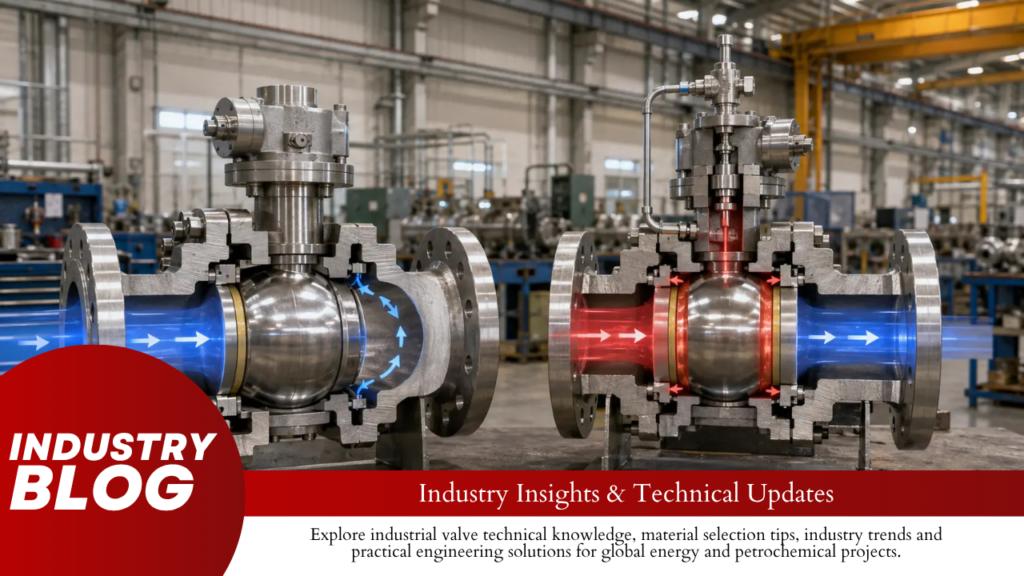
SPE is the better seat design for automatic cavity-pressure relief. DPE is the better seat design when pressure from either side must keep the seat against the ball and provide a second isolation barrier.Use SPE/SPE when trapped cavity pressure may safely return to a connected pipe. Use DPE/DPE when two tested barriers are required from either valve end, but add automatic cavity relief if liquid can be trapped. Use SPE/DPE when two barriers are required from one fixed pressure direction. The pressure behavior described below mainly applies to trunnion-mounted ball valves with spring-loaded moving seat rings. Floating ball valves use ball movement to load the downstream seat and should be checked separately. SPE vs DPE Under the Same Pressure Pressure Condition SPE Seat DPE Seat Pressure enters from the pipe end Moves toward the ball Moves toward the ball Cavity pressure becomes higher Can move away from the ball Moves more firmly toward the ball Automatic relief through the seat Yes, after the opening differential is reached Normally no Can one seat hold pressure from both sides? Not as a lasting full-pressure barrier Yes, subject to the approved design and test Common complete arrangement SPE/SPE DPE/DPE Common valve function API-style DBB DIB-1 Main risk Relief may enter an unsafe pipe end Liquid pressure may remain trapped between the seats SPE and DPE describe one seat. DBB, DIB-1 and DIB-2 describe the complete valve. A supplier should not claim DIB performance only because DPE seats are installed. The seat arrangement, pressure direction and factory test must all match. 100 Bar Can Create 10–20 kN of Seat Force The seat force comes from pressure acting over an effective ring-shaped area: Seat force = pressure × effective pressure area Pressure Effective Area Calculated Force 50 bar 1,000 mm² 5 kN 100 bar 1,000 mm² 10 kN 150 bar 1,000 mm² 15 kN 100 bar 2,000 mm² 20 kN These are calculation examples, not valve ratings. The real effective area is set by the seat-ring diameters, rear-seal positions and internal pressure passages. Doubling the pressure doubles the pressure-generated force. Doubling the effective area also doubles the force. This is why two seats of similar size can behave differently when their rear seals are installed at different diameters. At low differential pressure, the springs provide most of the seat load. At higher pressure, fluid pressure adds more force. A DPE seat can therefore seal from both pressure directions, but it can still leak at low pressure if the springs, ball surface, seat surface or rear seals are damaged. An SPE seat opens only after cavity pressure creates enough force to overcome: Spring preload Rear-seal friction Seat-to-ball friction Pressure acting in the closing direction Dirt or deposits behind the seat ring The opening pressure and reseating pressure may differ. The test report should record both values instead of stating only “self-relief passed.” At 100/80/20 Bar, Only the Right SPE Can Relieve A closed valve may have three different pressures: left-side pressure, cavity pressure and right-side pressure. Left Side Cavity Right Side Seat Pressure Difference 100 bar 50 bar 0 bar Right SPE sees a 50-bar opening differential 100 bar 80 bar 20 bar Right SPE sees 60 bar; left SPE remains pressure-loaded toward the ball 100 bar 110 bar 90 bar Left SPE sees 10 bar; right SPE sees 20 bar 80 bar 80 bar 80 bar No cavity-to-line differential In the 100/80/20-bar case, cavity pressure does not exceed the 100-bar left side. It can still relieve through the right SPE because the cavity is 60 bar above the right side. Each SPE seat responds only to: Cavity pressure Pressure at its own adjacent valve end Its spring and friction forces The seat does not compare both pipe pressures and actively choose the lowest side. The actual opening differential must be supplied or tested for the specific valve. A 20°C Rise Can Add About 80 Bar in an Idealized Cavity A body cavity may contain process liquid, hydrotest water, condensate, cleaning fluid or liquid entering through a leaking seat. A completely liquid-filled cavity can gain pressure quickly when heated. A simple screening calculation is: Pressure rise ≈ bulk modulus × volume expansion coefficient × temperature rise Using an idealized water-like liquid near room temperature: Bulk modulus: 2.0 GPa Volume expansion coefficient: 0.0002 per °C No gas pocket No leakage No seat movement No valve-body expansion Temperature Rise Idealized Pressure Rise 5°C 2 MPa, about 20 bar 10°C 4 MPa, about 40 bar 20°C 8 MPa, about 80 bar 30°C 12 MPa, about 120 bar These values show the risk of liquid trapping; they are not predictions for a real valve. Actual pressure depends on the fluid properties, gas volume, starting pressure, valve-body flexibility, seal compression and leakage paths. API 6D Addendum 3 requires automatic cavity relief when liquid trapping is possible. For temperatures up to 250°F or 121°C, the cavity-relief pressure must not exceed a 33% differential above the applicable valve pressure rating.[1] Valve Rating at Temperature 33% Differential Arithmetic Upper Value 100 bar 33 bar 133 bar 160 bar 52.8 bar 212.8 bar 250 bar 82.5 bar 332.5 bar The table only shows the arithmetic. The 33% figure is a maximum limit under the stated conditions, not a standard relief-valve setting. The final setting must also allow for relief-device tolerance, backpressure, pressure accumulation and the ratings of connected fittings and instruments. API 6D also requires the manufacturer to determine whether liquid can be trapped with the valve open, closed or in both positions. Some valves use a hole through the ball or another internal pressure-balance passage. That feature must appear on the approved sectional drawing. More causes and pressure patterns are covered in the guide to pressure buildup inside a closed ball valve. SPE/SPE Relieves Pressure but Does Not Give Full DIB An SPE/SPE valve has one self-relieving seat at each end. In a standard symmetrical design, either seat can become the pressure-side seat. Condition SPE/SPE Response Pressure comes from the left Left SPE
What Information Is Missing from Most Ball Valve RFQs? | Process Data, Design Conditions, Special Tests
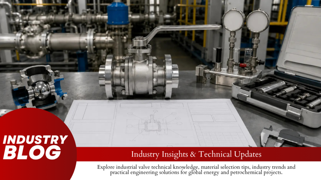
Most incomplete ball valve RFQs are missing the fluid composition, worst operating case, maximum opening and closing differential pressure, seat direction, leakage limit, actuator supply range, exact soft-part materials, test percentage, and document scope.“NPS 8, Class 600, carbon steel ball valve for natural gas” is not enough. The supplier still needs to know whether the gas is wet, whether H₂S or solids are present, whether the valve closes against 13 bar or 78 bar differential pressure, and whether every valve requires gas-seat testing. Minimum RFQ Fields Data group Minimum information Missing-data risk Fluid Name, composition, phase, water, corrosive components, solids Wrong body, trim, seat, seal, packing, or lubricant Pressure Normal, maximum operating, design, opening differential, closing differential Wrong pressure rating or undersized actuator Temperature Normal range, design minimum and maximum, cleaning, ambient limits Seat deformation, packing leakage, or excessive torque Function Isolation, ESD, blowdown, pigging, throttling, drain, bypass Wrong bore, seat, actuator, or valve type Sealing Pressure direction, cavity relief, leakage rate, test method Valve seals in the wrong direction or fails acceptance testing Actuator Minimum, normal, maximum supply; fail position; stroke time Valve cannot complete the required movement Testing Test name, standard, medium, pressure, duration, percentage Late price increase, retesting, or delivery delay Documents Drawings, BOM, torque, certificates, ITP, deviation list Design differences remain hidden before production Standard and Edition Standard Use in the RFQ API Specification 6D Pipeline and related piping valves within its scope ISO 14313 Requirements that supplement API 6D for applicable pipeline valves API Standard 608 Metal ball valves for petroleum, petrochemical, and industrial service within its scope ASME B16.34 Pressure-temperature ratings, materials, construction, examination, testing, and marking API Standard 598 or ISO 5208 Inspection, shell testing, and closure testing ASME B16.34 applies to new valve construction and covers pressure-temperature ratings, dimensions, materials, examination, testing, and marking for the valve types within its scope.[1] API Specification 6D is in its 25th edition. API lists Addenda 1, 2, and 3 and Errata 1, 2, and 3 for that edition. State the exact contractual document set instead of writing only “latest edition.”[2] ISO 14313:2025 supplements API Specification 6D, 25th edition, for the pipeline valves covered by its scope.[3] API Standard 608, 7th edition, became effective on October 2, 2025. Its size, class, material, construction, and end-connection limits must be checked before it is specified.[4] API lists API Standard 598, 11th edition, as the current published edition of its valve inspection and testing standard.[5] ISO 5208:2015 covers pressure-boundary integrity, closure tightness, and the strength of the closing mechanism. Use it with the selected valve product standard.[6] Use this document order when requirements conflict: Purchase order Approved valve data sheet Project valve specification Piping material specification Inspection and test plan Referenced valve standard Manufacturer’s standard Fluid and Contaminants Fluid item RFQ entry Parts affected Main fluid Name and concentration range All wetted parts Fluid phase Liquid, gas, vapor, slurry, or two-phase Seats, cavity, flow path, actuator torque H₂S and CO₂ Concentration or partial pressure Body, ball, stem, seats, bolting, welds Water Water content and possible free water Corrosion and sour-service assessment Chlorides Normal and maximum concentration Stainless steel, duplex, overlay, springs, fittings Viscosity Value at minimum and maximum temperature Operating torque and flow loss Vapor pressure Value at operating temperature Flashing and two-phase flow review Treatment chemicals Methanol, glycol, inhibitor, solvent, detergent Seats, O-rings, packing, gaskets, lubricant Temporary fluids Steam, nitrogen, flushing water, cleaning chemicals Temperature and chemical compatibility Do not write only “natural gas,” “produced water,” “amine,” or “seawater.” Material selection changes when water, H₂S, chlorides, solvents, oxygen, or solid particles are added to the same base fluid. For side-entry valves, compare the body, ball, stem, seat ring, overlay, bolting, and soft-part materials against the fluid data in the side-entry ball valve material guide. Operating Cases Case Valve position Upstream pressure Downstream pressure Temperature Must operate? Normal operation Open or closed Normal value Normal value Normal range State requirement Start-up State position Start-up value Start-up value Start-up value Yes or no Emergency shutdown Moving to fail position Maximum possible Minimum possible Emergency value Yes Depressurization Open, closed, or moving Falling Falling Minimum expected State requirement Steam-out Open, closed, or cycling Cleaning pressure Cleaning pressure Steam temperature State requirement Long shutdown Open or closed Residual pressure Residual pressure Ambient or maintained Breakaway after storage Use the worst value from each case for material limits, seat design, torque, actuator sizing, cavity relief, and testing. The highest pressure, highest temperature, and highest operating differential pressure may come from three different cases. Pressure and Temperature Pressure item Illustrative value Normal operating pressure 55–78 barg Design pressure 92 barg Downstream pressure during normal closing 65 barg Normal closing differential pressure 13 bar Downstream pressure during emergency closing 0 barg Emergency closing differential pressure 78 bar The emergency closing differential pressure in this example is six times the normal closing value. Valve torque and actuator sizing must use the 78-bar case when emergency closure is required. Temperature item Illustrative value Required check Normal operating range 15–80°C Continuous material and torque limits Minimum design temperature −29°C Body impact properties and soft-part flexibility Maximum design temperature 100°C Body and seat pressure-temperature ratings Steam-out condition 180°C at 3 barg Seat, packing, gasket, lubricant, and valve position Minimum ambient temperature −10°C Actuator, accessories, coating, and lubricant Maximum ambient temperature 50°C Actuator seals, solenoid, switches, and electronics If the valve is exposed to 180°C steam, state whether it is pressurized, whether it must operate, how long the condition lasts, and whether the normal soft seats remain installed. ISO 28921-1:2022 covers applicable low-temperature and cryogenic isolation valves with design temperatures from −50°C to −196°C.[7] For LNG, liquid nitrogen, liquid oxygen, or other very cold fluids, state the minimum temperature, bonnet extension, insulation thickness, packing position, test temperature, cold leakage limit, and cold torque. The available construction can be checked against the forged cryogenic ball valve range. Solids, Flow, and Cycling Solid item Illustrative RFQ entry Material Rust and sand Normal particle size 50–150 μm Maximum particle size 300 μm
How to Compare Ball Valve Quotations with Different Technical Deviations | TBE, Exclusions, Lifecycle Risk
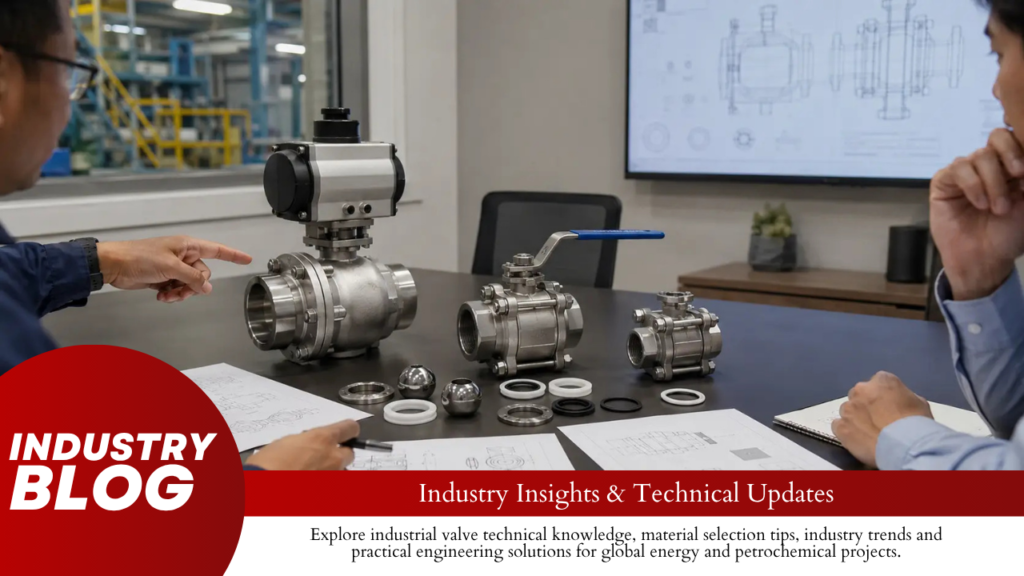
Direct answer: Reject any quotation that fails the required pressure-temperature rating, material compatibility, bore, cavity relief, end connection, safety qualification, or actuator torque. For the remaining quotations, add every excluded item to calculate a normalized bid price. Then add expected maintenance, repair, spare-parts, replacement, and shutdown costs. A mandatory technical failure must be corrected or rejected; it must not be hidden inside a price adjustment. Review stage Question Result Technical acceptance Can the offered valve safely perform the stated service? Accept, clarify, or reject Scope normalization What equipment, tests, documents, or site work are missing? Normalized bid price Lifecycle review What will the valve cost to maintain, repair, and replace? Lifecycle-adjusted cost Reject These Bids Before Price Comparison A quotation should not enter the final price ranking while any of the following items remains noncompliant: Allowable pressure is below the design pressure at the stated design temperature. Body, trim, seat, seal, packing, or bolting materials are unsuitable for the fluid. The minimum bore cannot pass the required cleaning pig or inspection tool. The valve cannot safely relieve trapped body-cavity pressure. Flanges, weld ends, face-to-face dimensions, or pipe bore do not match the piping. The actuator cannot operate the valve at maximum differential pressure. The actuator can apply more torque than the stem or drive train can safely carry. Mandatory fire-safe, fugitive-emission, sour-service, or low-temperature evidence does not cover the offered valve. The supplier will not identify the actual manufacturing and testing factory. Missing evidence is not the same as a confirmed deviation. Mark it as an open clarification until the supplier provides the drawing, certificate, calculation, material list, or test plan needed to make a decision. Status Use it when Typical example Clarification The offer may comply, but proof is missing No bore dimension, torque calculation, or certificate scope Minor deviation No effect on safety, function, installation, or service life Different drawing format or acceptable nameplate layout Major deviation The design, performance, test scope, or maintenance method changes Different seat, bore, body design, NDE scope, or face-to-face length Reject The valve cannot safely or reliably perform the required service Wrong material, insufficient rating, no cavity relief, or undersized actuator Use These Columns in the TBE Use one row for every requirement that can change safety, performance, installation, testing, documents, delivery, or cost. TBE field Required entry Reference Data-sheet item, specification clause, drawing note, or standard Purchaser requirement The exact material, design, performance, test, or document required Supplier offer What the supplier has actually included Evidence Quotation page, drawing, data sheet, calculation, certificate, or ITP Status Comply, clarify, minor deviation, major deviation, or reject Effect Safety, flow, leakage, installation, maintenance, schedule, or cost Required action Revised offer, drawing, test, calculation, certificate, or approval Cost adjustment Cost needed to place the bid on the required supply basis Remaining risk Risk still carried by the purchaser after acceptance Approver Responsible process, piping, materials, mechanical, inspection, or procurement person Do not calculate one overall compliance percentage. A quotation that meets 39 of 40 requirements can still be unacceptable if the missing requirement is pressure rating, cavity relief, material compatibility, or emergency operation. Record document conflicts as open items. If the quotation states PEEK, the data sheet states reinforced PTFE, and the drawing states “vendor standard,” the seat material is not confirmed. Verify the Standard, Edition, and Licensed Factory Write the exact standard edition and applicable addenda in the TBE. API identifies API Specification 6D, 25th Edition, November 2021, with Addendum 3 issued in March 2025 and an API Monogram Program effective date of September 5, 2025.[1] “Designed to API 6D” does not prove that the supplied valve will carry an API Monogram. Check the legal manufacturer, factory address, product scope, and current licence status in the API Composite List.[2] API describes the Monogram Program as a licensing system that permits licensed manufacturers to apply the mark to products made under the applicable programme requirements.[3] The factory named in the certificate should match the factory that performs assembly, pressure testing, marking, and release. The practical checks for licence scope and serial-number records are also covered in the API 6D ball valve manufacturing guide. ASME B16.34 covers pressure-temperature ratings, materials, dimensions, tolerances, nondestructive examination, testing, and marking for applicable valve construction.[4] It does not by itself confirm the correct seat, seal, bore, actuator, cavity-relief arrangement, fluid compatibility, or project-specific testing. When a supplier offers an “equivalent” standard, require a table showing each different clause and its effect. A general statement of equivalence is not enough. Confirm Pressure Rating at the Actual Temperature Ask for the allowable pressure of the exact body material at the maximum design temperature. Do not approve a valve from the class number alone. For an illustrative Class 600 valve offered for 100 barg at 180°C, the supplier should provide the applicable pressure-temperature rating for the stated body material. The review must also cover: Body and closure Pressure-boundary bolting Ball and stem Seat inserts and seat seals Body gaskets and O-rings Stem packing Gearbox lubricant Actuator, solenoid, switches, tubing, and controls If the body is suitable for 180°C but the offered soft seat has a stated continuous limit of 150°C, the complete valve is not suitable for the design condition. Check the valve against normal operation and every credible temporary condition: Maximum closing differential pressure Steam cleaning or hot flushing Cold start and minimum ambient temperature Rapid gas depressurization Vacuum Thermal cycling Emergency shutdown Long periods without movement Where liquid can be trapped in the valve cavity, API 6D Addendum 3 requires automatic cavity relief. For temperatures up to 121°C, the addendum limits cavity-relief pressure to no more than 33% differential pressure above the valve pressure rating.[1] Require the supplier to show: Whether liquid can be trapped in the open or closed position Which seat or device relieves pressure The direction of relief The relief-pressure basis Any external relief valve, line, or discharge connection The test used to confirm the function Measure the Smallest Bore and Map the Seat Pressure Path The
Which Vendor Drawings Must Be Approved Before Ball Valve Production? | GA, Cross-Section, Actuator, Nameplate
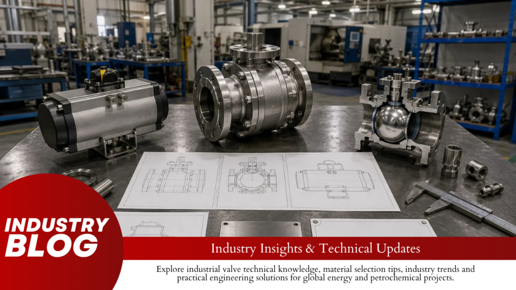
Approve the GA and cross-section drawing with BOM before releasing project-specific machining or internal materials. Approve the actuator package before buying the actuator or making the bracket and coupling. Approve the nameplate before permanent marking. Add weld-end, extension, control, cavity-relief and lifting drawings only when those features are included in the order.The purchase order and information requirements specification must state whether each drawing is for approval, review, information or final record. IOGP S-562L defines the required information content, format, submission time and purpose; the drawing title alone does not create a production hold.[1] Drawing Approve before Do not release when GA drawing End machining, external interface work and final assembly Dimensions, bore, end details, operator envelope or connection positions remain unclear Cross-section and BOM Pressure-boundary material purchase and internal component manufacture Seat action, cavity relief, stem retention, materials or item numbers are unclear Actuator and mounting package Actuator purchase, bracket fabrication and coupling machining Minimum output, maximum output, drive-train limit, fail action or mounting details are missing Nameplate and marking drawing Stamping, engraving and attachment-hole work Tag, serial number, material, rating, standard or certification marks do not match the order Weld-end or pup-piece drawing End machining and pressure-containing welding Actual pipe dimensions, bevel, transition, material, welding or NDE requirements are missing Extension drawing Stem, bonnet, protective tube and remote-line manufacture Length, support, sealing, insulation limit or access is not fixed Control diagrams Tubing, wiring, terminal and panel work Ports, voltage, signals, fail action or accessory tags conflict with the data sheet Cavity-relief drawing Relief-device purchase and external piping work The pressure source, relief route, setting, discharge point or isolation control is unclear IOGP S-562 Version 4.0 was published in April 2026 for procurement against API 6D 25th Edition and Addendum 2. API 6D Addendum 3 was issued on March 5, 2025. When both are named in the order, state whether Addendum 3 applies and which document takes priority where the requirements differ.[2] Reject a GA That Does Not Show the Complete Installed Package The GA must identify the exact valve supplied, including: Purchase order and item number Valve tag number or tag range Manufacturer and valve model Drawing number and revision Valve size and pressure class Applicable design standard and edition Body construction Full-opening or reduced-opening bore Flanged, butt-weld or other end connection Lever, gearbox or actuator type Fixed operator orientation Bare-valve and assembled weights One GA may cover several tags only when their body design, dimensions, bore, materials, seat arrangement, end connections and operator package are identical. Remove unused options from the production drawing. Check these dimensions against the valve data sheet and piping layout: Face-to-face or end-to-end length Valve centreline to operator top Overall height, width and length Handwheel diameter or lever travel Complete actuator and accessory envelope Flange dimensions and bolt holes Drain, vent and injection-point positions Space for removing the actuator or gearbox Space for adjusting or replacing stem packing Specified dimensional tolerances ASME B16.10 covers face-to-face and end-to-end dimensions for the valve types within its scope. Use the edition named in the order and check that the vendor drawing matches the selected valve pattern and pressure class.[4] Illustrative check: An approved face-to-face dimension is 900 mm, but the finished valve measures 904 mm. The 4 mm difference may prevent installation between fixed flanges. Do not accept the valve because the difference “looks small”; compare it with the specified tolerance. For applicable flanged-end configurations under API 6D Addendum 3, lateral misalignment is limited to 2 mm for NPS 4 and smaller valves and 3 mm for larger valves. These are flange-related limits in the amended clauses, not general tolerances for every GA dimension.[2] Show the complete operator package, not only the actuator housing. Include: Limit-switch box Solenoid valve Filter regulator Pressure gauges Boosters and quick-exhaust valves Terminal boxes and cable entries Local control station Pneumatic or hydraulic tubing Manual override Illustrative check: A bare actuator is 620 mm wide. After adding the switch box, solenoid and filter regulator, the complete package reaches 780 mm. The missing 160 mm can place an accessory inside an adjacent pipe or platform. Where IOGP S-562 applies, the lever length is limited to 610 mm or twice the valve face-to-face or end-to-end length, whichever is less. The handwheel diameter is limited to 800 mm or the valve face-to-face or end-to-end dimension, whichever is less. A 75 mm clearance is required between the outer edge of the lever or handwheel and components within its movement range.[3] Use Actual Flange and Pipe Dimensions For flanged valves, the GA or end-detail drawing must state: Flange standard and edition Pressure class Raised-face or ring-type-joint facing Facing finish Flange outside diameter and thickness Bolt-circle diameter Bolt-hole quantity and diameter Ring groove designation where applicable For butt-weld valves, use the actual mating pipe dimensions. ASME B16.25 covers butt-welding-end preparation, including bevels and internal shaping of heavy-wall components.[5] The drawing must state: Pipe outside diameter Nominal and actual wall thickness Pipe schedule Corrosion allowance Bevel angle Root face Finished valve-end inside diameter Internal transition diameter and length Pup-piece material and length Corrosion-resistant overlay termination Pressure-containing weld location Required heat treatment and NDE Do not release machining from a note that says “ends to suit pipe.” A Schedule 40 pipe and Schedule 80 pipe of the same nominal size have different inside diameters. Heavy-wall pipe, overlay and corrosion allowance can change both the finished bore and the minimum remaining wall. Approve Piggability from the Smallest Finished Bore Do not approve a piggable valve from the words “full bore.” Record the smallest finished opening at: Upstream valve end Upstream seat ring or retainer Ball entrance Ball-port centre Ball exit Downstream seat ring or retainer Downstream valve end Compare those dimensions with the exact pig or inspection tool. The checks in how to confirm whether a full-bore ball valve is truly piggable cover pipe Schedule, seat bore, internal steps, weld shape and transition length. Reject the drawing when it leaves any of these items open: Minimum finished bore Seat or
How to Check Whether an API 6D License Covers the Offered Ball Valve | Product Scope, Facility Name, Expiry
Accept the license only when four fields match: API 6D, Ball Valves, the actual manufacturing facility, and an Active status on the valve’s Date of Manufacture. Check the live API Composite List during bid review and again before final release. A certificate PDF does not replace the live record. Approve Only When Four Fields Match Field Pass condition Hold or reject condition Specification The facility record shows API 6D The supplier submits API Q1, API 608, API 6DSS, or another program instead Product Ball Valves appear in the licensed product scope The API 6D scope lists only gate, plug, check, or axial valves Facility The legal name and physical address match the factory making the order The certificate belongs to a sales office, parent company, or another group factory Status and date The facility is Active on the Date of Manufacture The record is Applicant, Expired, Suspended, Inactive, Canceled, or Withdrawn The API Monogram Program authorizes licensed manufacturers to apply the Monogram to equipment that meets the applicable API product specification and is made under an API Spec Q1-compliant quality management system.[1] Search These Fields in the Composite List Enter the manufacturer’s legal company name. Select API 6D under Specification/Standard. Select Ball Valves under Product. Compare the city, state or province, country, and full factory address. Open the complete facility record. Save a dated screenshot or PDF printout. The API Composite List is the free directory for companies participating in the API Monogram and related certification programs.[2] Record at least these eight fields: Legal company name Licensed facility name Full facility address API specification Licensed products Current status Relevant effective or expiry dates Date of your search FM-002 states that the Composite List contains facility-specific details and current and past licenses, including products, license numbers, status, and relevant dates.[3] API Composite List checked on [date]. The same facility record shows API 6D, Ball Valves, the proposed manufacturing address, and the current license status. The relevant dates have been compared with the planned Date of Manufacture. Mark the License Unverified When No Record Appears Replace the brand name with the legal company name. Remove suffixes such as Ltd., LLC, Inc., or Co., Ltd. Search again without punctuation. Use a shorter part of the company name. Check whether the company recently changed its name. Search by API 6D and country. Ask the supplier for the exact name registered with API. If the facility still does not appear, enter Unverified in the technical evaluation and keep the offer on Hold. Do not accept the certificate, but do not call it fraudulent without evidence. API publishes examples of certificates it did not issue and states that the Composite List is updated in real time when applications and license statuses change.[4] Reject API 6D Records Without Ball Valves API separates the API 6D license into five product groups: Gate Valves Plug Valves Ball Valves Check Valves Axial Valves The facility must have Ball Valves in its scope. An API 6D license for gate or check valves does not cover the offered ball valve.[5] Record shown Decision API 6D — Ball Valves Continue checking the factory, status, dates, and product records API 6D — Gate Valves or Check Valves only Reject the license claim for the ball valve API Q1 only Request a separate API 6D Ball Valves license API 608 — Ball Valves Do not treat it as API 6D unless the project accepts API 608 API 6DSS Check whether the project requires the separate subsea valve program API publishes API 6D, API 6DSS, and API 608 as separate licensing programs. A license under one specification does not provide the scope of another.[6] Do not accept these statements as license evidence: API-certified manufacturer API-approved supplier API Q1 factory API member company API 6D application in progress API 6D available on request Our parent company holds the license Our partner factory holds the license Use One Facility Record for the Whole Decision The seller, brand owner, manufacturer, and licensed facility may be different companies. Identify each one. Role Required information Seller Company issuing the quotation and invoice Brand owner Name under which the valve is sold Manufacturer Organization responsible for making the valve Licensed facility Physical factory covered by the API record Final-acceptance facility Location accepting the finished valve A distributor can sell an API Monogrammed valve, but the distributor’s office does not become the licensed factory. The quotation, drawings, ITP, marking, and final records must identify the actual manufacturer. Do not combine: Ball Valves scope from Factory A Active status from Factory B Matching address from Factory C All required information must come from the same facility record. FM-002 states that licenses are non-transferable and that products covered by the license must be made at the facility identified on the Certificate of Authority.[3] Compare These Five Address Fields Legal company name Plant or building number Street or industrial zone City, state, or province Country Field API record Supplier document Decision Company ABC Valve Co., Ltd. ABC Valve Co., Ltd. Pass Plant Plant 2 Plant 1 Hold Industrial zone East Industrial Zone East Industrial Zone Pass City Ningbo Ningbo Pass Country China China Pass Four matching fields do not cancel the Plant 1 versus Plant 2 mismatch. Treat them as different facilities until the supplier proves otherwise. An abbreviated street name, missing postal code, or verified English translation may be acceptable. A different building, plant number, city, or country requires written clarification. API requires licensed organizations to report location, name, and ownership changes. An ownership change may require a new license number.[3] Keep OEM Orders Traceable to the Real Licensee For an OEM or private-label order, require: Legal name of the API licensee Licensed factory address Relationship between the seller, brand owner, and manufacturer Company controlling the drawings and bill of materials Facility performing final acceptance Organization applying the API Monogram Draft product marking showing the actual licensee If another company’s name appears on the valve, FM-002 requires the licensee’s name and license number to
