
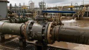
Data to Collect First
The following values should appear in the valve data sheet. The units matter because terms such as “high chloride” or “some sand” are too vague for material selection.
| Parameter | Unit or Data Format | Why It Matters |
|---|---|---|
| Total dissolved solids | mg/L | Shows overall water salinity |
| Chloride | mg/L | Affects pitting and crevice-corrosion risk |
| Dissolved oxygen | µg/L or ppb | Can increase carbon steel corrosion and change stainless steel behaviour |
| CO2 and H2S | Dissolved concentration or partial pressure | Affects corrosion and sour-service material limits |
| Sand concentration | mg/L or mass percentage | Affects seat and coating wear |
| Particle size | d50, d90 and maximum size in µm | Shows whether particles can enter seat clearances or block closure |
| Pressure and temperature | bar or MPa; °C | Controls pressure rating, material limits and actuator torque |
| Differential pressure | bar or MPa | Controls local velocity and erosion during operation |
| Operating torque | N·m | Provides a baseline for detecting sand, scale or internal damage |
Define the Service
Produced-water conditions change with the valve location. State where the valve will be installed before selecting materials.
- After a separator: water is the main phase, but oil, dissolved gas, fine sand and scale may remain.
- After water treatment: solids may be lower, while oxygen, bacteria and treatment chemicals may become more important.
- Water injection: the valve may face high pressure, oxygen entry, mixed-water scale and long shutdowns.
- Water disposal: deposits may collect during low flow or stagnation.
- Drain and flushing lines: short periods of very high solids loading may occur.
A valve upstream of the separator is exposed to oil, gas, water and slugs. It should be treated as multiphase wellstream service, not produced-water-only service.
For main pipeline isolation, bore, seat arrangement, pressure class and testing may need to follow an API 6D forged ball valve design.
Check the Water
Use a recent water analysis from the actual valve location. Produced-water chemistry can change as water cut rises, injection water reaches the well, treatment chemicals change or separation performance falls.
The analysis should include:
- Chloride and total dissolved solids
- pH and alkalinity
- Dissolved oxygen
- Dissolved CO2 and H2S
- Gas composition and total pressure
- Calcium, barium, strontium and sulfate
- Dissolved iron
- Oil and grease
- Suspended solids
- Corrosion inhibitor
- Scale inhibitor
- Biocide
- Methanol, glycol and other injected chemicals
USGS data show that conventional oil and gas produced waters can range from about 5,000 mg/L to more than 350,000 mg/L total dissolved solids. Chloride, sodium and calcium are commonly the main ions.[1]
The USGS National Produced Waters Geochemical Database contains records from roughly 18,000 oil, gas and brine wells, showing how widely water chemistry can vary between fields.[2]
Check the Sample
A laboratory report is useful only when the sample represents the pipeline conditions.
CO2 and H2S may escape when pressure is reduced. Oxygen can enter the bottle during sampling. Sand results can change sharply between normal production, startup and separator upset.
Record:
- Sampling point and date
- Line pressure and temperature
- Normal, startup or upset operation
- Whether the sample was depressurized
- Whether chemical injection was running
- How the sample was protected from air
- How quickly unstable components were tested
For severe service, compare samples from normal production and credible upset conditions. One clean sample may miss the condition that causes valve failure.
TDS and Chloride
Total dissolved solids and chloride are not the same measurement.
TDS is the approximate total amount of dissolved material. Chloride measures only chloride ions. Two water samples can have the same TDS but different chloride, calcium, sulfate and bicarbonate levels.
- Chloride affects stainless steel pitting and crevice-corrosion risk.
- Calcium and bicarbonate affect calcium carbonate scale.
- Barium, strontium and sulfate affect hard sulfate scale.
- Dissolved iron may indicate corrosion or iron-containing deposits.
Do not use one chloride limit to choose between 316L, duplex, super duplex and nickel alloy. Temperature, oxygen, pH, H2S, deposits, weld quality and stagnant crevices also affect the result.
Check the Solids
“Sand present” is not enough information. Ask for:
- Normal and maximum sand concentration
- d50 and d90 particle size
- Maximum particle size
- Particle shape and mineral type
- Scale particle size
- Sand-slug duration
- Startup and flushing conditions
d50 is the size below which 50% of the measured particles fall. d90 is the size below which 90% fall. These values show whether a low average result hides a smaller number of large particles.
| Practical Particle Band | Main Concern | Possible Valve Damage |
|---|---|---|
| 10–50 µm | Fine particles entering narrow clearances | Sand buildup behind seats, higher friction and rising torque |
| 50–250 µm | Repeated abrasive impact | Seat scratches, coating wear and loss of sealing contact |
| 250 µm–1 mm | Large particles reaching the sealing band | Deep scratches, seat indentation or incomplete closure |
| Above 1 mm | Large sand, scale or debris | Immediate blockage or mechanical damage during closing |
These particle bands are practical review groups, not fixed material-selection limits. Particle shape, velocity, concentration and pressure difference must also be considered.
Four solids patterns need different checks:
- Continuous fine sand: particles can enter the narrow space behind the seat.
- Short sand slugs: a high concentration can cut the downstream seat in a short time.
- Large startup particles: one particle may prevent full closure.
- Detached scale: hard, sharp scale can damage the ball and seat like sand.
Quartz is hard enough to scratch polymer seats and poorly supported coatings. Actual wear also depends on particle velocity, size, shape, concentration and impact angle.
Check the Flow
Provide:
- Normal and maximum flow rate
- Actual pipe inside diameter
- Normal and maximum velocity
- Gas volume fraction
- Maximum differential pressure
- Flow direction and possible reverse flow
- Operating frequency
- Time spent partly open
A fully open full-bore ball valve normally has little restriction. A partly open ball creates a narrow opening and a high-speed jet.
The jet can strike the downstream seat edge, ball bore, body cavity, end adaptor or downstream pipe. Sand carried by this jet can remove coating and cut a narrow leakage path.
The average pipe velocity does not show the much higher local velocity through a partly open valve. Severe service may require flow analysis, erosion calculations or testing with representative solids.
Avoid Throttling
A standard isolation ball valve should normally remain fully open or fully closed.
Repeated partial opening can cause:
- Seat-edge erosion
- Ball bore damage
- Coating loss
- Noise and vibration
- Unstable flow
- Leakage after closure
Use a purpose-built control valve when regular flow adjustment is required. A higher pressure class or harder coating does not make a standard isolation valve suitable for throttling.
Chloride Corrosion
Carbon steel and stainless steel do not fail in the same way.
Carbon steel mainly suffers general corrosion, under-deposit corrosion and local attack in stagnant areas.
Stainless steel can suffer:
- Pitting
- Crevice corrosion
- Chloride stress-corrosion cracking
- Under-deposit corrosion
Ball valves contain crevices behind seat rings, under O-rings, around body joints, near stem seals and at coating edges. Water trapped in these spaces can become more aggressive than the main flow.
The main bore may look clean while deep pits form inside the seat pocket. The complete valve design must be checked, not only the body grade.
Oxygen, CO2 and H2S
Oxygen can enter through tanks, pump seals, chemical systems, maintenance work and water-treatment equipment.
Even low oxygen contamination can materially change corrosion in chloride water containing CO2 or H2S.[3]
Oxygen can increase carbon steel corrosion. In warm chloride water, crevices and deposit-covered surfaces, it may also increase localized corrosion of stainless steel.
CO2 dissolves in water and forms carbonic acid. Carbon steel corrosion then depends on CO2 partial pressure, pH, temperature, velocity, chloride, protective scale and inhibitor performance.
H2S adds the risk of sulfide stress cracking, hydrogen-induced cracking and related damage.
ISO 15156-1:2020 covers the selection and qualification of cracking-resistant metallic materials used in H2S-containing oil and gas production environments. It supplements rather than replaces the valve design standard.[4]
ISO 15156-2 also states that its carbon and low-alloy steel requirements address cracking, not general or localized metal loss. Corrosion allowance and corrosion control must therefore be reviewed separately.[5]
Sour-service checks should cover the body, ball, stem, seat rings, springs, bolting, overlay, hardfacing and weld heat-affected zones. Material grade alone is not enough; hardness, heat treatment, cold work and welding also matter.
Scale and MIC
Scale can damage a valve even when natural sand levels are low.
- Calcium carbonate can restrict seat movement.
- Barium and strontium sulfate can form hard abrasive particles.
- Iron sulfide can collect in the cavity, spring grooves and drains.
- Deposits can create local under-deposit corrosion.
Microbiologically influenced corrosion can develop in stagnant cavities, low-flow areas and systems with poor biocide control. Research has shown that sulfate-reducing bacteria and their biofilms can contribute to steel corrosion in oilfield environments.[6]
A water bacteria count alone cannot confirm or rule out MIC. Deposit samples, corrosion products, damaged surfaces and operating history may also need examination.
Corrosion-Erosion
Corrosion-erosion occurs when chemical attack and particle impact act together:
- A corrosion product or protective film forms.
- Sand removes the film.
- Fresh metal is exposed.
- Corrosion starts again.
The combined damage can be greater than corrosion or erosion acting alone.
Typical locations include the downstream seat edge, ball bore, body cavity near the flow path, drain entrance, reduced-bore transition and coating edge.
The damaged area may be narrow. Average wall-thickness readings can miss a small groove that causes serious internal leakage.
Carbon Steel
Carbon steel may be suitable where oxygen is controlled, solids are limited, corrosion inhibitor is reliable and inspection is practical.
Its advantages are lower cost, good strength, wide availability and easier fabrication.
A body corrosion allowance does not protect thin springs, seat edges, stem surfaces or narrow drain passages. These parts may fail before the thick pressure wall.
An inhibitor-dependent design should confirm:
- Minimum effective dose
- Continuous or batch injection
- Pump reliability
- Mixing quality
- Protection during shutdown
- Field coupon or probe results
- Whether inhibitor reaches the valve cavity
316L, Duplex and Nickel Alloys
316L may work in relatively mild, cool and clean produced water. Risk rises with higher chloride, temperature, oxygen, low pH, deposits and long shutdowns.
The lower carbon content of 316L reduces sensitization during welding. It does not provide a large increase in chloride pitting resistance compared with 316.
A common alloy comparison formula is:
PREN = %Cr + 3.3 × %Mo + 16 × %N
Typical approximate PREN values are:
- 316L: 24–26
- 22Cr duplex: 32–36
- Many super duplex grades: 40 or higher
PREN compares alloy chemistry. It does not account for welding, heat treatment, surface finish, crevices, deposits or H2S. Some formulas also include tungsten or other alloying elements.[7]
Duplex stainless steel normally provides higher strength and better chloride resistance than 316L. Super duplex provides a larger pitting and crevice-corrosion margin, but both depend on correct heat treatment, phase balance and welding.
Nickel alloys such as Alloy 625, Alloy 825 and Alloy C-276 may be considered when chloride, temperature, oxygen, pH and H2S exceed the practical limits of stainless steel. Specify the exact UNS grade rather than only writing “nickel alloy.”
Corrosion-resistant alloys are not erosion-proof. A nickel-alloy ball can still wear under continuous sand impact.
For a wider comparison of body and trim choices, see the carbon steel, stainless steel and duplex ball valve material guide.
Material Selection Direction
| Service Condition | Possible Design Direction | Checks Still Required |
|---|---|---|
| Moderate chloride, low oxygen and limited solids | Carbon steel with corrosion control or stainless internal parts | Temperature, inhibitor reliability and shutdown conditions |
| Higher chloride and elevated temperature | Duplex or super duplex review | Oxygen, pH, H2S, welding and crevice conditions |
| H2S-containing produced water | Sour-service-qualified metals | Hardness, heat treatment, partial pressure and material limits |
| Severe corrosion with carbon steel pressure body | CRA weld overlay or corrosion-resistant cladding | Dilution, final thickness and exposed edges |
| Continuous sand or repeated sand slugs | Protected metal seats and qualified hard coating | Particle data, differential pressure, torque and leakage |
This table provides screening directions, not fixed material rules. Final selection should use the complete service data and the project corrosion review.
Material Options
| Design | Main Benefit | Main Limitation |
|---|---|---|
| Solid corrosion-resistant alloy | No internal overlay interface | Higher material and manufacturing cost |
| Carbon steel with CRA weld overlay | Thick corrosion barrier over a strong body | Depends on welding, dilution and final thickness |
| Carbon steel with electroless nickel | Uniform thin deposit on complex surfaces | Pinholes and edge damage can expose the substrate |
| CRA substrate with carbide coating | Combines corrosion and wear resistance | Higher cost and more inspection requirements |
Weld Overlay
Alloy 625 weld overlay is commonly applied to carbon steel body cavities, seat pockets, end adaptors and drain passages.
A finished thickness near 3 mm is often specified for severe valve service, but the project must define the minimum effective thickness after machining.
Check:
- Minimum finished thickness
- Iron dilution
- Finished surface chemistry
- Cracks, lack of fusion and porosity
- Machining allowance
- Surface finish
- Overlay termination points
The filler-metal certificate does not prove the chemistry of the finished surface. Dilution from the carbon steel substrate must also be controlled.
Electroless Nickel
Electroless nickel-phosphorus provides uniform coverage, higher surface hardness and moderate corrosion and wear resistance.
ASTM B733-22 classifies these coatings by phosphorus content, service severity and post-plating heat treatment. It also covers thickness, adhesion, hardness and porosity testing.[8]
Finished thicknesses of about 50–100 micrometres are used in some valve specifications. The correct value depends on the service class, base material and qualified plating process.
Higher phosphorus generally improves salt and acid resistance. Heat treatment can increase hardness, but it may also change coating structure and cracking risk.
Electroless nickel is not sacrificial. If chloride water reaches carbon steel through a pinhole or damaged edge, corrosion may spread beneath the coating.
WC-CoCr Coating
HVOF WC-CoCr is widely used on metal-seated balls and seat rings exposed to abrasive solids.
The tungsten carbide supplies hardness. The cobalt-chromium binder holds the carbide particles together and adds toughness and corrosion resistance.
Published HVOF coating tests have reported thicknesses of about 177–279 micrometres and hardness values of about 989–1,269 HV0.3, with results changing according to powder and spray conditions.[9]
Another peer-reviewed study reported WC-CoCr hardness values of about 1,177–1,256 HV0.3 and porosity between approximately 0.54% and 1.11% for the tested coating systems.[10]
| Inspection Item | Common Project Starting Range | Important Detail |
|---|---|---|
| Finished coating thickness | 150–300 µm | Measure after final grinding |
| Microhardness | About 1,000–1,400 HV0.3 | State the test load and reading locations |
| Porosity | Often controlled below 1–2% | State the image-analysis method and magnification |
| Sealing-surface roughness | Ra 0.4 µm or smoother in many applications | State measurement direction and evaluation length |
| Local thickness | Project-defined minimum | Check edges, transitions and contact bands |
| Metallographic check | Qualified witness coupon | Use the same powder batch and spray procedure |
These values are common starting points, not universal acceptance limits. The final requirement must match the powder, substrate, valve size, grinding method and qualified coating procedure.
Failure can start from binder corrosion, connected pores, poor adhesion, grinding cracks, excessive thickness or chipped edges.
The ball and seat coatings must be selected as a matched pair. A very hard ball against a softer or poorly supported seat can damage the seat contact band.
Other Hard Surfaces
Cr3C2-NiCr provides wear and oxidation resistance and may be used where temperature is too high for the preferred tungsten carbide system.
Cobalt-based hardfacing resists galling and metal-to-metal wear. It is useful on seat edges and bearing surfaces but may resist fine abrasive sand less effectively than dense WC-CoCr.
Select the surface treatment from the expected damage mechanism, not hardness alone.
Soft or Metal Seats
Soft seats can provide very low leakage when the fluid is clean. Common materials include PTFE, reinforced PTFE, modified PTFE and PEEK.
PTFE has low friction and good chemical resistance but can creep under pressure. Reinforced PTFE has better strength, while PEEK provides higher strength and temperature capability. Sand can still cut or scratch all three.
Metal seats are usually considered for continuous solids, frequent cycling, higher temperature and high differential pressure.
Metal seats also have limits. They can suffer:
- Coating indentation
- Scratches
- Galling
- Erosion grooves
- Particles trapped in the sealing band
Metal seated does not automatically mean zero leakage. State the test medium, pressure, direction, holding time and permitted leakage.
See the forged soft-seated floating ball valve page for clean-service product options. For dirty or abrasive service, compare its seat limits with the required metal-seat and coating system.
Seat Pockets
Fine sand can enter the space behind the seat and cause high torque, blocked springs, O-ring damage, corrosion and incomplete closure.
Ask the manufacturer:
- How solids are kept out
- Where solids can collect
- Whether the seat pocket can be flushed
- Whether wiping or scraping action is used
- Whether the design has been tested with representative solids
A narrow gap does not guarantee protection. Fine particles can enter and compact behind the seat.
Floating or Trunnion
In a floating ball valve, pressure moves the ball slightly toward the downstream seat. This design is common in smaller sizes.
A trunnion-mounted valve supports the ball at the top and bottom while the seats move toward it. This is common in larger sizes and higher pressures.
Trunnion construction can reduce operating torque, but it also adds bearings and internal spaces where solids may collect. Size, pressure, seat design, bearing protection and drain access must all be checked.
For larger produced-water lines, review the trunnion-mounted ball valve selection factors before specifying the construction.
Full Bore
ISO 17292 covers full-bore, reduced-bore and double-reduced-bore metal ball valves for petroleum and related industrial applications.[11]
A full-opening designation does not guarantee an exact match with every pipe inside diameter or pig geometry.
Verify:
- Ball bore diameter
- Seat opening
- End transition
- Actual pipe schedule
- Internal grooves and projections
- Pig body and sealing-disc dimensions
Full bore reduces restriction when fully open but does not prevent erosion during partial opening.
Cavity, Drains and Small Parts
Water trapped inside the body cavity can expand as temperature rises. The seat design must provide a safe pressure-relief path.
Common arrangements include self-relieving seats, double-piston-effect seats and external thermal relief. The specification should state the relief direction and how H2S-containing fluid will be handled.
The drain should reach the lowest practical point of the cavity. A drain above the bottom may leave a bed of sand inside the valve.
Also specify the actual grades for:
- Stem
- Seat springs
- Bolting
- Packing
- O-rings
Descriptions such as “stainless spring” or “chemical-resistant O-ring” are not enough.
Actuator Torque
Factory torque is normally measured on a new, clean valve. Field torque can rise because of sand, scale, corrosion products, packing ageing, low temperature, long shutdowns and high differential pressure.
The actuator calculation should include:
- Minimum and maximum supply pressure
- Break-to-open torque
- Running torque
- End-to-close torque
- Expected in-service torque increase
- Stem and gearbox limits
Record the clean-valve torque during commissioning. Later readings should be compared at similar pressure, temperature and actuator-supply conditions.
An oversized actuator can twist the stem or damage the seats. A torque increase should be investigated rather than hidden by adding more actuator force.
Standards and Tests
API 6D defines requirements for the manufacture of pipeline and piping valves. API currently lists the 25th edition with Addendum 3 published in March 2025.[12]
ASME B16.34 covers pressure-temperature ratings, materials, dimensions, examination, testing and marking for flanged, threaded and welding-end valves.[13]
ISO 5208:2015 covers pressure-boundary testing and closure-tightness verification for metallic valves. It is used together with the relevant valve product standard.[14]
| Test or Inspection | Data to Record | Purpose |
|---|---|---|
| Shell pressure test | Medium, pressure, temperature, holding time and result | Checks the pressure boundary |
| Seat leakage test | Pressure, direction, duration and measured leakage | Checks shutoff performance |
| Low-pressure seat test | Gas pressure, test direction and leakage | Checks seat loading at low differential pressure |
| Torque test | Break, running and closing torque in N·m | Checks actuator sizing and internal friction |
| Material verification | PMI, hardness, heat treatment and traceability | Confirms the specified materials |
| Overlay inspection | Final thickness, chemistry and NDE results | Checks corrosion-barrier quality |
| Coating inspection | Thickness, HV load, porosity and Ra | Checks wear-surface quality |
| Sand or slurry test | Particle data, cycles, torque rise and final leakage | Checks performance after representative solids exposure |
Standard clean-water testing proves that a new valve meets the stated pressure and leakage requirements. It does not prove long-term resistance to sand.
A sand or slurry test should define particle type, concentration, size, flow velocity, differential pressure, temperature, number of cycles, permitted torque increase and final leakage.
See the API 6D ball valve testing overview for a closer look at shell, seat and functional testing.
Failure Signs
| Symptom | Possible Cause | First Check |
|---|---|---|
| Leakage after closure | Trapped sand, cut soft seat, erosion groove, coating scratch or incorrect actuator stop | Travel position, drain contents and seat test |
| Torque rises slowly | Fine sand, scale, packing ageing or bearing corrosion | Torque trend and cavity drain sample |
| Torque rises suddenly | Large particle, compacted sand, broken spring or drive fault | Stop operation and inspect the drive and cavity |
| Metal particles in drain fluid | Coating damage, hardfacing wear, corrosion products or upstream damage | Particle analysis and internal inspection |
Field leakage should be traced to the stem, body joint or seat before repair begins. The ball valve leakage troubleshooting guide provides a practical checking order.
Purchase Checklist
| Item | Required Information |
|---|---|
| Water | Chloride, TDS, pH, oxygen, CO2, H2S, scale ions, oil and chemicals |
| Solids | Normal and maximum concentration, d50, d90, maximum size, shape and slug duration |
| Operation | Pressure, temperature, flow, velocity, differential pressure and operating frequency |
| Valve duty | Isolation or control, bore, floating or trunnion, cavity relief and leakage rate |
| Materials | Body, overlay, ball, seats, coatings, stem, springs, packing and O-rings |
| Inspection | Standard edition, PMI, hardness, coating checks, pressure test, torque test and solids test |
Conclusion
Produced-water ball valve selection starts with measured chloride, oxygen, H2S, sand concentration, d50, d90, temperature and differential pressure. Carbon steel may work where inhibition and oxygen control are reliable, while duplex, nickel-alloy overlay or solid CRA may be needed in more corrosive water. For abrasive duty, metal seats and 150–300 µm HVOF WC-CoCr coatings are common starting points, but finished thickness, HV0.3 hardness, porosity, surface roughness and coating edges must be inspected. Record clean-valve torque at commissioning and define leakage limits before ordering so rising torque or seat damage can be found early.







