
Start by confirming which side is pressurized, what the body arrow means, and whether the valve is floating-ball or trunnion-mounted. Do not reverse, repair, or replace the valve before checking its drawing, seat arrangement, cavity pressure, and actual closed position.
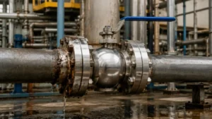
Find the Leak Path
A falling pressure reading does not prove that fluid has passed through the complete valve. First identify where the fluid is going.
Through-seat leakage means fluid passes from the pressurized pipeline side, through the closed ball-and-seat system, and reaches the opposite pipeline side.
Common leak paths include:
- A gap between the ball and seat
- A scratch across the ball sealing track
- Debris trapped on the seat
- A cut or deformed soft-seat insert
- Leakage behind the movable seat ring
- A damaged O-ring, lip seal, or backup ring
- An internal relief hole facing the wrong side
Cavity bleed flow means fluid passes the first seat, enters the body cavity, and leaves through the drain or vent. This confirms that the first seat is passing, but it does not prove that fluid has crossed the second seat.
Cavity relief flow may be normal. An SPE seat can open after cavity pressure rises high enough, releasing trapped pressure toward the lower-pressure line.
External leakage means fluid escapes through the stem packing, body joint, flange, weld, drain fitting, vent fitting, or pressure-containing body. ISO 15848-1 covers external leakage from valve stem seals and body joints; it does not set through-seat leakage limits.[1]
If fluid is escaping to the atmosphere, stop the test and follow the approved site isolation procedure.
Check Pressure Direction
The normal flow direction is not always the pressure direction when the valve is closed.
For example, normal flow may run from Side A to Side B. During shutdown, backflow, testing, or equipment isolation, Side B may remain pressurized after Side A has been drained. The valve is then loaded in the reverse direction.
Use fixed names during testing:
- Side A: one physical end of the valve
- Side B: the other physical end
- Pressure direction: the side supplying pressure during the test
- Normal flow: the usual process-flow direction
An arrow on the valve may show:
- Normal or preferred flow
- The required sealing direction
- The high-pressure end
- The cavity-relief direction
- The correct position of an internal relief hole
Do not guess what the arrow means. Check the valve drawing, data sheet, installation manual, and factory test report.
Before testing, record:
- Manufacturer, model, and serial number
- Valve size and pressure class
- Floating or trunnion-mounted design
- Seat and secondary-seal materials
- SPE, DPE, or mixed seat arrangement
- High-pressure-end marking
- Actuator model and settings
- Previous test and repair records
The ball valve installation and post-installation testing guide explains why valve orientation, pipe cleanliness, alignment, and actuator setup should be checked before service.
Know the Valve Design
The meaning of one-direction leakage depends on whether the ball moves toward the seat or the seat moves toward the ball.
Floating ball valve: The ball is supported mainly by the seats and stem. When the valve is closed, line pressure pushes the ball slightly toward the downstream seat. That seat normally carries most of the sealing load.
Many floating ball valves can seal from either end. Some are directional because they use:
- A drilled pressure-relief hole
- Different seats on the two sides
- One soft seat and one metal seat
- An uneven seat-support design
- A V-port or segmented ball
- A preferred direction for lower torque or less wear
If a floating valve leaks only when Side A is pressurized, the pressure may be loading a damaged Side B seat or pushing that seat across a scratched part of the ball.
Trunnion-mounted ball valve: The ball is held by trunnions, bearings, or support plates. The seat rings move toward the ball and are normally loaded by springs and fluid pressure.
SPE and DPE normally describe these pressure-responsive trunnion seat systems. They should not automatically be used to describe every floating ball valve.
For more detail, see the comparison of floating and trunnion-mounted ball valves. Typical floating designs are also shown on the forged soft-seated ball valve page.
Understand SPE and DPE
Pressure acts on the effective area of a movable seat ring. The basic relationship is:
Hydraulic force = pressure difference × effective area.
The following values are simple calculations, not valve-design limits:
| Pressure difference | Effective seat area | Hydraulic force |
|---|---|---|
| 10 bar | 20 cm² | 2,000 N |
| 50 bar | 20 cm² | 10,000 N |
| 100 bar | 20 cm² | 20,000 N |
At the same 50 bar pressure difference, increasing the effective area from 20 cm² to 30 cm² raises the hydraulic force from 10,000 N to 15,000 N. This explains why a small change in seat diameter can noticeably change sealing force and operating torque.
A force of 10,000 N is about 1.02 tonne-force. Actual seat load also depends on spring force, seal friction, seat dimensions, body movement, and contact between the ball and seat.
SPE means Single Piston Effect.
Pressure from the pipeline side normally pushes an SPE seat toward the ball. Pressure from the body-cavity side can push it in the opposite direction.
An SPE seat has two main jobs:
- Seal against pressure from its pipeline side
- Release excessive cavity pressure toward a lower-pressure line
The seat does not necessarily open as soon as cavity pressure starts rising. It may continue sealing until cavity pressure reaches its relief point.
A typical sequence is:
- Side A is pressurized.
- The Side A seat begins to pass.
- Pressure enters the body cavity.
- The opposite SPE seat continues holding.
- Cavity pressure reaches the relief point.
- The opposite seat moves away from the ball.
- Pressure is released into the lower-pressure line.
This may produce repeated pressure rise, sudden flow, pressure drop, and resealing. It does not automatically mean that both seats are damaged.
DPE means Double Piston Effect.
Pressure from either side of a DPE seat can push it toward the ball. If the first seat passes, cavity pressure can load the second DPE seat and create another barrier.
The drawback is trapped cavity pressure. Two DPE seats normally cannot release cavity pressure through the seats, so the valve needs a dedicated cavity-relief arrangement approved by the manufacturer.
More detail on seat loading and secondary seals is available in the API 6D seat design and pressure-balance guide.
Compare Seat Arrangements
Bidirectional shutoff is not the same as having two independent barriers against pressure from one side.
| Seat arrangement | Normal behavior | Second barrier | Cavity relief |
|---|---|---|---|
| SPE/SPE | Either pipeline end can usually act as the pressure side | The second seat may hold temporarily, but it is not a lasting high-pressure barrier after self-relief starts | Normally through an SPE seat toward the lower-pressure line |
| DPE/DPE | Both seats can be loaded by pipeline or cavity pressure | May provide a second barrier in both directions if the complete valve is designed and tested for it | Needs a separate approved relief arrangement |
| SPE/DPE | Combines cavity relief with a pressure-loaded second seat | Normally available in one specified direction | Normally through the SPE side |
For a mixed arrangement, assume Side A has the SPE seat and Side B has the DPE seat.
When Side A is pressurized, the Side A SPE seat is the first barrier. If it passes, cavity pressure pushes the Side B DPE seat toward the ball, allowing Side B to act as the second barrier.
When Side B is pressurized, the DPE seat is the first barrier. If it passes, cavity pressure acts behind the Side A SPE seat. Once the relief point is reached, the SPE seat may release pressure toward Side A.
For the required DIB-2 direction, the DPE seat normally needs to be downstream of the pressure source. The valve drawing and test procedure must confirm the arrangement.
Separate DBB from DIB
DBB, or double block and bleed, commonly describes two sealing surfaces with a bleed point between them. A single-valve DBB design may block pressure from either end without providing two lasting high-pressure barriers against one pressure source.
DIB, or double isolation and bleed, means the second seat can provide another barrier against the same pressure source. A common DIB-1 arrangement uses two DPE seats. A common DIB-2 arrangement uses one SPE and one DPE seat.
DPE describes how one seat reacts to pressure. It does not prove that the complete valve has passed a DIB test.
A DBB compact manifold is also different from one ball valve containing two internal seat rings. A product name alone does not decide whether an isolation method is safe.
OSHA’s construction confined-space rule defines double block and bleed as two in-line valves that are closed and locked or tagged, with the drain or vent between them opened and locked or tagged.[2]
This OSHA definition applies to the stated confined-space rule. It should not be treated as the definition for every valve specification or maintenance procedure.
Before opening downstream equipment, confirm:
- How many physical isolation devices are required
- Which valve or seat is the first barrier
- Which valve or seat is the second barrier
- Whether the bleed is open and clear
- Whether pressure is still entering the cavity
- Whether a blind or physical disconnection is required
- Whether the site isolation procedure allows the arrangement
Rule Out a False Failure
A valve can appear to have seat damage when it is not fully closed or when the test equipment is leaking.
Check the actual ball position. A limit switch can show “closed” before the ball reaches the correct sealing position.
Possible causes include:
- Incorrect actuator-stop settings
- A loose stem coupling
- Gearbox backlash
- A worn drive key
- Low air or hydraulic pressure
- An undersized actuator
- A bent stem
- A damaged trunnion bearing
- Debris stopping full rotation
- A misaligned mounting bracket
A quarter-turn ball valve normally travels about 90 degrees. In a diagnostic example, an actuator that stops at 87.5 degrees is 2.5 degrees short of full travel. The position switch may still indicate “closed,” but the ball may not be in its best sealing position. A few degrees of error can matter, especially in large or metal-seated valves.
Reverse pressure may also increase seat, stem, or bearing friction. The actuator may close the valve in the normal direction but stop short when pressure is reversed.
ISO 12490 defines mechanical-integrity and sizing requirements for electric, pneumatic, and hydraulic actuators installed on pipeline valves.[3]
Use the ball valve torque curve guide to check breakaway, running, and reseating torque. Use the highest expected pressure difference and the least favorable pressure direction.
Check the test equipment:
- Test temporary hoses, fittings, blind flanges, and instruments.
- Confirm that the body cavity is filled, drained, or vented as required.
- Remove trapped air from a liquid test where required.
- Allow pressure and temperature to stabilize.
- Verify the mechanical closed position.
- Measure actual flow instead of using pressure drop alone.
- Repeat both pressure directions under the same conditions.
For planning purposes, a small water-filled test assembly may stabilize in about 5–10 minutes, while a large gas-filled assembly may need 15–30 minutes or longer. These are practical examples, not fixed acceptance times. The approved test procedure controls the actual stabilization period.
Gauge range also matters. For a 50 bar test, a 0–100 bar gauge normally shows small changes more clearly than a 0–600 bar gauge. Gauge accuracy, calibration, and range must still meet the approved test procedure.
Check Pressure Level
A pressure-loaded seat may leak at low pressure but seal more tightly when the pressure increases. Weak springs, dirt, or restricted seat movement are common reasons.
The following is an illustrative diagnostic example, not a universal acceptance limit:
| Test condition | Side A outlet flow | Side B outlet flow | Possible meaning |
|---|---|---|---|
| 2 bar nitrogen | 40 mL/min | 3 mL/min | Check the Side A-loaded seat, springs, and full closure |
| 20 bar nitrogen | 12 mL/min | 2 mL/min | Higher pressure may be helping the Side A seat seal |
| 50 bar water | No visible outlet flow | No visible outlet flow | The high-pressure liquid test may be hiding a low-pressure gas problem |
The example shows a trend only. The valve cannot be accepted or rejected until the measured results are compared with the applicable standard and purchase specification.
Check Temperature and Medium
Some valves seal when cold but leak when hot. Others do the opposite.
Hot-only leakage may come from:
- Different expansion of the ball, seat, body, and coating
- A shifted metal-seat contact band
- Soft-seat material losing stiffness
- Uneven body heating
- Actuator or bracket movement
- Thermal expansion of trapped cavity liquid
Cold-only leakage may come from:
- Soft-seat shrinkage
- Elastomer hardening
- Higher seal or bearing friction
- Lower actuator output
- Different contraction of the ball and seat
The following example shows how to identify a temperature-related trend. It does not state the temperature limit of any seat material:
| Fluid temperature | Test pressure | Measured outlet flow |
|---|---|---|
| 20°C | 30 bar | 2 mL/min |
| 60°C | 30 bar | 11 mL/min |
| 100°C | 30 bar | 34 mL/min |
| Cooled back to 20°C | 30 bar | 4 mL/min |
In this example, leakage increases as temperature rises and falls again after cooling. That pattern points toward thermal movement or material softening rather than pressure direction alone.
The test medium also matters:
- Gas can pass through smaller gaps than many liquids.
- Gas pressure changes with test volume and temperature.
- Trapped air can make a liquid test unstable.
- High-viscosity liquid can hide a small leak path.
- Water can move loose debris or push it into a scratch.
- Wax, scale, coke, polymer, or crystals can stop a seat ring moving freely.
Use the same medium, pressure, temperature, holding time, and measurement method when comparing Side A and Side B.
The PTFE, PEEK, and metal seat comparison explains why seat material, temperature, particles, and operating cycles must be considered together.
Read the Cavity Pressure
Body-cavity pressure helps identify which seat is passing, but it must be read together with the seat arrangement.
With Side A pressurized and Side B open:
- A fast cavity-pressure rise can mean the Side A seat is passing.
- Continuous cavity-bleed flow confirms that Side A is not fully isolating the cavity.
- Stable cavity pressure with no Side B flow may mean a Side B DPE seat is holding.
- Side B flow while cavity pressure is still low may mean second-seat damage.
- Cavity pressure that rises before Side B flow starts may show SPE self-relief.
- Repeated pressure rise and sudden release may show an SPE seat opening and resealing.
The following is an illustrative SPE diagnostic trend. The 32 bar value is not a universal SPE relief setting:
| Elapsed time | Side A pressure | Cavity pressure | Side B observation |
|---|---|---|---|
| 0 minutes | 50 bar | 0 bar | No flow |
| 2 minutes | 50 bar | 12 bar | No flow |
| 5 minutes | 50 bar | 28 bar | No flow |
| 6 minutes | 50 bar | 32 bar | Short flow pulse |
| 7 minutes | 50 bar | 24 bar | Flow stops |
A pressure-rise-and-release pattern like this is more consistent with an SPE seat reaching a relief point than with a permanently open leakage path. The result must still be compared with the manufacturer’s seat design.
Cavity pressure can also rise because of:
- Trapped liquid heating up
- Pressure left from an earlier test
- A leaking drain or vent valve
- A leaking injection or bypass connection
- Heating of trapped gas
For valves within the scope of API 6D, Addendum 3 requires automatic cavity relief where liquid can become trapped. At temperatures up to 250°F (121°C), the cavity-relief pressure must remain within the limit defined as a differential pressure 33% above the valve pressure rating.[4]
Do not apply this requirement automatically to valves outside API 6D’s scope.
Never loosen a drain plug, vent plug, injection fitting, or body connection to check cavity pressure. Use the installed drain or vent system under an approved procedure.
Inspect the Damage
Disassemble the valve only after both pipeline sides and the body cavity have been isolated, drained, vented, cleaned, and checked for stored pressure.
A wider comparison is available in the field ball valve leak troubleshooting guide.
Ball and seat surfaces
- A full circular scratch often means a hard particle was trapped while the ball turned.
- A scratch crossing the sealing band can form a direct leak path.
- A wide contact band on one side and a narrow band on the other can show seat tilt, ball misalignment, or body distortion.
- Local coating loss can come from erosion, galling, impact, or incorrect polishing.
- A broken metal-seat contact band can point to poor alignment, lost roundness, or damaged trunnion support.
Do not polish or machine a coated ball without approved repair limits. Removing material changes its diameter, roundness, surface finish, and contact with the seat.
For hard-coated sealing surfaces, see the metal-seated ball valve maintenance guide.
Soft-seat inserts
- A sharp cut usually points to debris or a damaged ball edge.
- Extruded material points to excessive clearance, pressure, heat, or weak backup support.
- Swelling or softening points to chemical incompatibility.
- Blisters can be caused by rapid gas decompression.
- A permanent flat area can be caused by compression set or cold flow.
- Burned or glazed material points to excessive heat or friction.
Secondary seals
- Cuts and nibbling point to sharp edges or extrusion.
- One-sided extrusion can show reverse pressure, excessive clearance, or a reversed backup ring.
- A twisted seal can result from poor installation or wrong lubrication.
- Hard, swollen, or soft seals may be unsuitable for the fluid or temperature.
Seat rings and springs
- Corrosion, deposits, or galling can stop the seat ring moving.
- Blocked pressure holes can prevent the seat from loading correctly.
- Broken or weak springs often cause low-pressure leakage.
- Uneven spring height can create uneven seat contact.
- Damage behind the seat can create a bypass even when the visible face looks good.
Body strain
- Misaligned pipes can distort the valve body.
- Unsupported valve or actuator weight can shift the ball and seats.
- Weld shrinkage can restrict seat movement.
- Uneven flange loading can make a valve pass on a test bench but fail after installation.
Record ball diameter, roundness, sealing-band width, seat-ring travel, guide clearance, spring height, seal material, backup-ring direction, closed-position error, and operating torque. Compare them with the OEM limits.
Set the Acceptance Limit
There is no single leakage limit for every ball valve.
The limit depends on:
- Soft or metal seat
- Valve size and pressure class
- Test medium
- Test pressure
- Pressure direction
- Holding time
- Measurement method
- Product standard
- Purchase specification
ISO 5208 covers pressure-boundary testing, closure tightness, and the strength of the closing mechanism for metallic valves. It is intended to be used with the applicable valve product standard.[5]
Terms such as “zero leakage,” “bubble-tight,” and “no visible leakage” are incomplete unless the test conditions and allowed rate are stated.
| Test item | Side A pressure | Side B pressure |
|---|---|---|
| Test medium | ||
| Inlet pressure | ||
| Outlet pressure | ||
| Body-cavity pressure | ||
| Fluid temperature | ||
| Stabilization time | ||
| Holding time | ||
| Measured leakage rate | ||
| Allowed leakage rate | ||
| Gauge range and resolution | ||
| Mechanical valve position |
A complete record might read: “Side A at 50 bar, Side B vented, nitrogen at 22°C, 15-minute stabilization, 10-minute hold, measured outlet flow 18 mL/min.” The 18 mL/min value cannot be called acceptable or unacceptable until it is compared with the correct standard and purchase specification.
For more test-planning detail, see the API 6D shell, seat, and functional test guide.
Repair and Retest
Replacing a damaged seat is not enough if the original cause remains.
- For particle damage, improve flushing, filtering, and operating practice.
- For chemical damage, check the full fluid composition and cleaning chemicals.
- For gas decompression damage, check the seal material and depressurization speed.
- For heat damage, check the real temperature and heating cycle.
- For reverse-pressure damage, review shutdown and backflow conditions.
- For piping strain, correct pipe alignment and support.
- For incomplete closure, correct the actuator, coupling, and stops.
- For trapped cavity pressure, restore the approved relief path.
Repair the valve when approved spare parts are available, the pressure boundary is sound, and the complete valve can be retested.
Replace it when:
- The body or another pressure part is cracked or badly eroded.
- The ball or seat pocket cannot be restored within limits.
- The seat arrangement cannot be confirmed.
- Traceable spare parts are unavailable.
- The valve is unsuitable for the real reverse-pressure condition.
- The repair would cancel a required certification.
- The valve cannot pass the required tests.
Do not convert SPE to DPE, reverse seat rings, drill or block relief holes, remove springs, or change seat materials without written engineering approval.
After repair, check:
- Pressure-boundary strength
- Side A seat sealing
- Side B seat sealing
- Low-pressure closure
- Specified high-pressure closure
- Cavity bleed and relief operation
- The second barrier in the required DIB direction
- Actuator travel and torque
- Stem, drain, vent, and fitting leakage
The following is an example of a useful repair comparison. It is not a universal acceptance table:
| Check | Before repair | After repair |
|---|---|---|
| Low-pressure nitrogen leakage | 45 mL/min | 3 mL/min |
| Mechanical closing angle | 87.5° | 90.0° |
| Largest spring-height difference | 1.8 mm | 0.2 mm |
| Directional result | Side A failed | Side A and Side B results matched |
This pattern suggests that the original problem involved incomplete closure and uneven spring loading. Final acceptance still depends on the specified leakage limit.
The trunnion-mounted ball valve maintenance guide provides more detail on cleaning, seal replacement, lubrication, and post-repair checks.
Quick Diagnosis
| Observed result | Likely cause | First check | What confirms it |
|---|---|---|---|
| New valve leaks only in reverse | Directional design, wrong installation, or wrong seat arrangement | Arrow, high-pressure end, and seat drawing | Documents show one required pressure direction |
| SPE/DPE valve leaks from one side | DPE seat is on the wrong side for the required isolation direction | Physical location of both seats | DPE seat is not downstream of the pressure source |
| Low-pressure test fails but high-pressure test passes | Weak springs, dirt, or restricted seat movement | Springs and seat-ring travel | Cleaning or spring replacement restores low-pressure sealing |
| High-pressure test fails | Seal extrusion, excessive movement, or coating damage | Secondary seals, ball, seats, and bearings | Damage is found on the pressure-loaded side |
| Cavity pressure rises quickly | First-seat leakage or another cavity pressure source | Pressurized-side seat and cavity fittings | Temperature is stable and other connections are tight |
| Cavity pressure rises before outlet flow starts | SPE self-relief may be occurring | Seat type and cavity-pressure trend | Flow begins at a repeatable relief pressure |
| Cavity holds and the outlet stays dry | The second DPE seat may be holding | DPE location and allowed leakage rate | Outlet leakage stays within the required limit |
| Leak starts after cycling | Debris or sealing-track damage | Ball and seat surfaces | A fresh scratch, cut, or trapped particle is found |
| Water test passes but gas test fails | A small sealing gap or unstable gas test | Temperature, test volume, and seat condition | Measured gas flow repeats under stable conditions |
| Cold test passes but hot test fails | Thermal movement or material softening | Seat material and hot alignment | Leakage follows temperature |
| Bench test passes but installed valve fails | Piping strain or actuator misalignment | Pipe supports, flanges, and mounting bracket | Performance improves after external loads are corrected |
| Both directions leak heavily | Incomplete closure or major internal damage | Actual ball position | Travel error, broken drive parts, or severe seat damage is found |
Standards
API Specification 6D, 25th Edition, defines requirements for pipeline valves, including design, manufacturing, assembly, testing, marking, and documentation.[6]
ISO 14313:2025 covers several valve types used in oil and gas pipelines, including ball valves, and supplements API 6D, 25th Edition.[7]
These standards do not replace the valve-specific drawing, seat-force diagram, factory test report, actuator calculation, or OEM repair limits.
Conclusion
A one-direction leak should be checked in a fixed order: confirm Side A and Side B pressure, identify floating, SPE, DPE, or mixed seats, verify full 90-degree closure, and compare cavity pressure with outlet flow. A 50 bar pressure difference acting on 20 cm² creates about 10,000 N of seat force, so reversing pressure can produce a very different result. If the valve should seal both ways, inspect the loaded seat, ball track, secondary seals, springs, actuator travel, and piping strain. After repair, repeat the same low- and high-pressure tests in both directions and judge the result against the correct leakage standard.







