
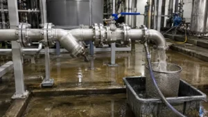
How Seats Are Damaged
A ball valve seals where the ball contacts the seat. A small scratch across this contact area can create an internal leak path.
Damage often happens in this order:
- Weld slag, metal chips, sand, rust, or other debris enters the valve.
- The debris stays near the seat, behind a movable seat ring, or inside the body cavity.
- The valve is operated before the debris has been removed.
- The particle is pressed between the ball and seat.
- The seat is cut or dented, or the ball is scratched.
| Damage | Common Cause | Result |
|---|---|---|
| Seat cut | Sharp weld slag, wire, or metal chips | A narrow internal leak path |
| Seat dent | A bolt, stone, thick scale, or other hard object | Permanent local deformation |
| Ball scratch | A hard particle dragged across the ball during operation | Leakage that remains after the particle is removed |
| Seat-edge erosion | Dirty high-speed flow through a partly open valve | Loss of sealing contact |
| High torque | Debris in the cavity, seat pocket, bearing, or sealing area | Difficult movement or actuator overload |
| Coating damage | Abrasive debris or an unsuitable cleaning chemical | Shorter sealing life on a metal-seated valve |
Seat materials do not fail in the same way:
- PTFE and reinforced PTFE: Sharp particles can cut the surface or press grooves into it. The sealing performance of a forged soft-seated floating ball valve depends on a smooth ball and an undamaged seat.
- PEEK and other strong polymers: These materials normally resist wear better than standard PTFE, but hard metal particles can still scratch or indent them.
- Metal seats: Hard seats handle heat and many particle-containing services better than soft seats, but their lapped surfaces and coatings can still be scored. A metal-seated ball valve still needs a clean pipeline.
- Elastomer seals: O-rings and other secondary seals may swell, soften, shrink, or harden when exposed to an unsuitable flushing liquid.
Valve structure also affects where debris collects. In a floating valve, line pressure moves the ball toward the downstream seat. In a trunnion-mounted valve, the ball is supported while movable seats press against it. Seat pockets, springs, bearings, drains, and the body cavity can hold fine particles even when the main bore looks clean. The floating and trunnion ball valve comparison explains the main structural differences.
Check the Valve and Pipeline Data
Do not choose the flushing pressure, temperature, flow, valve position, or strainer limit from a general rule. Record the values approved for the actual system.
| Item | What to Confirm |
|---|---|
| Ball valve | Tag number, valve type, full or reduced bore, seat material, pressure direction, and required flushing position |
| Flushing liquid | Liquid type, temperature, cleanliness, and material compatibility |
| Pressure limit | The lowest approved limit among the pipe, valves, hoses, strainers, gaskets, pumps, and instruments |
| Flow requirement | The calculated flow or target velocity for each pipe diameter |
| Temporary strainer | Screen opening, total area, open area, support, flow direction, and maximum differential pressure |
| Pump | Stable operating range, suction pressure, available NPSH, discharge limit, and cavitation signs |
| Acceptance | Particle limit, final-screen condition, turbidity, oil, conductivity, chemical residue, or another project limit |
API Specification 6D covers design, manufacturing, assembly, testing, marking, and documentation requirements for pipeline and piping valves. It does not replace the site flushing procedure or the manual for the installed valve.[1]
ASME B16.34 covers pressure-temperature ratings, materials, testing, marking, dimensions, and other requirements for applicable valves. The pressure class shown on a valve is therefore not the only limit that needs to be checked.[2]
Where ASME B31.3 applies, the connected process piping also has requirements for design, materials, fabrication, assembly, examination, inspection, and testing.[3]
Hydrostatic Testing Is Not Flushing
| Activity | Main Purpose | What It Does Not Prove |
|---|---|---|
| Hydrostatic test | Checks the pressure integrity of the piping system | It does not prove that the pipe is clean |
| Pipeline flushing | Removes loose debris and fluid contamination | It does not replace the required pressure test |
A line can pass a hydrostatic test and still contain rust, weld slag, sand, oil, gasket pieces, or coating flakes. Filling and draining the line may also loosen material from the pipe wall. A flush may therefore be needed after pressure testing.
Before testing, confirm whether the valve must be open, closed for an approved seat test, removed, or replaced with a temporary spool. Do not assume that the valve body rating allows the same pressure to be applied across a closed seat.
ISO 5208 covers factory examinations and tests used to check the pressure boundary and closure tightness of metallic valves. It does not provide one universal field test for every valve after pipeline flushing.[4]
Decide Whether the Valve Should Stay
Leaving every valve in the line is not always the safest choice. A temporary full-bore spool may give the debris a clearer path and protect an expensive valve.
| Condition | Practical Action |
|---|---|
| Large amounts of weld slag, scale, stones, or construction debris are expected | Remove the valve or install a temporary spool |
| The valve has a V-port, attenuator, small passages, or special control trim | Follow the trim-specific procedure and consider removal |
| The valve is reduced-bore and large debris may be present | Check the minimum bore and blockage risk before leaving it installed |
| The cleaning liquid may attack the seat, seals, or coating | Obtain written material approval or remove the valve |
| The valve cannot be inspected or tested after flushing | Use a lower-risk temporary arrangement |
| The line has already been mechanically cleaned and the valve manual permits flushing in place | Leave the valve fully open with suitable upstream protection |
A temporary spool should have a suitable internal diameter, pressure rating, gasket system, and support. Its bore should not contain a large weld bead, sharp step, loose scale, or another debris trap.
Set the Valve Position
A normal on-off ball valve in the through-flushing path should usually remain fully open. A full-open valve has a larger flow area and exposes less of the seat edge to the main debris stream.
A partly open valve creates a narrow opening. The liquid speeds up through this opening and can carry hard particles directly across the ball and seat. Do not use an on-off ball valve to regulate dirty flushing flow.
| Valve Condition | Position During Through-Flushing |
|---|---|
| Full-bore on-off ball valve | Fully open unless the manual requires another arrangement |
| Reduced-bore on-off ball valve | Fully open after checking bore size, velocity, pressure loss, and debris risk |
| Trunnion-mounted isolation valve | Fully open unless the valve manual states otherwise |
| Floating isolation valve | Fully open unless removed or replaced with a spool |
| V-port or segmented control valve | Use the trim-specific procedure; removal or bypass may be safer |
| Valve outside the flushing route | Isolate it under the approved valve lineup |
| Valve with unknown internals | Identify it before flushing |
For a reduced-bore valve, compare the expected debris size with the smallest internal opening. The smaller passage also creates higher local velocity at the same volume flow.
Some valves have a preferred pressure direction because of their seat design or cavity-relief path. This is important for soft-seated trunnion ball valves using SPE, DPE, or mixed seat arrangements. Check the valve drawing and body marking before flushing in either direction.
Do not cycle the valve while the line still carries hard debris unless the approved procedure specifically requires it. After the line is clean and isolated, follow the valve manual for cavity draining, pressure release, and functional testing.
Prevent Unplanned Valve Movement
An actuated valve can move because of a control signal, loss of power, instrument-air failure, hydraulic pressure, or a spring-return actuator.
- Confirm that the valve has reached its mechanical open stop.
- Compare the local indicator with the control-room signal.
- Check the actuator fail position.
- Control electrical, pneumatic, hydraulic, spring, and stored mechanical energy.
- Use an approved mechanical lock where the valve must be physically prevented from moving.
- Record temporary control overrides and remove them after flushing.
OSHA requires potentially hazardous stored or residual energy to be relieved, disconnected, restrained, or otherwise made safe during servicing and maintenance.[5]
A car seal can show that someone moved a valve, but it may not stop the valve from moving. It does not replace actuator isolation or a mechanical lock.
Remove Large Debris First
Flushing should carry small remaining contamination. It should not be used to push welding rods, bolts, stones, rags, or large pieces of scale through installed valves.
| Debris Group | Examples | Main Risk |
|---|---|---|
| Hard debris | Weld slag, wire, metal chips, bolts, stones, and thick rust scale | Cuts seats, scratches balls, damages coatings, or blocks the bore |
| Soft debris | Rags, gloves, tape, plastic caps, gasket pieces, and packaging | Blocks strainers, branches, cavities, and small passages |
| Liquid contamination | Cutting oil, grease, paint, preservative, and cleaning chemicals | Attacks seals or contaminates the future process |
Use visual inspection, manual cleaning, vacuum cleaning, borescope inspection, magnetic retrieval, wiping, or pigging where the pipeline design allows it.
- Visual inspection: Useful at open ends, but it cannot prove that every branch is clean.
- Borescope: Useful around bends, but the viewing angle is limited.
- Vacuum cleaning: Works well for dry debris but not for wet or oily material.
- Magnetic retrieval: Removes many carbon-steel items but not stone, plastic, copper, aluminum, or some stainless steels.
- Pigging: Use only where the complete route can safely pass the selected pig.
Inspect low points, vertical risers, branch connections, reducers, vessel nozzles, dead legs, and valve cavities. Material in these areas may enter the main flow after the first flushing cycle.
Pipe cleanliness, flange alignment, and seat protection should also be checked during installation. The ball valve installation and seal-protection procedure covers these field checks.
Install Temporary Strainers
A temporary strainer can protect equipment, collect debris for inspection, or perform both jobs.
- Protection strainer: Installed upstream of a sensitive valve, pump, flowmeter, control valve, heat exchanger, or compressor.
- Acceptance strainer: Installed near the outlet to show what is leaving the flushed section.
An outlet strainer cannot protect a valve that the debris has already passed through.
Common designs include cone, truncated-cone, basket, and flat temporary screens. A cone normally provides more surface area than a flat screen in the same pipe size. A flat screen may block more quickly.
When the first circulation is expected to carry heavy debris, the approved procedure may use a coarse screen first and a finer screen later. The final screen must still protect the smallest sensitive downstream passage.
Install the strainer in the direction shown on its drawing. Do not assume that every cone tip faces the same way. Check the mesh side, supporting side, pressure direction, welds, collar, and internal clearance.
Do not place a cone tip where it can touch the ball, stem, seat, or another moving part. If flow is reversed, recheck the strainer direction and move protection strainers so they remain upstream of the equipment they protect.
Select the Screen Opening
Do not select a screen only by pipe size or mesh number. The actual opening also depends on wire diameter.
- Identify the most sensitive downstream equipment.
- Find the largest particle that the equipment can accept.
- Check the smallest passage in the protected flow path.
- Estimate the size, shape, hardness, and amount of expected debris.
- Select the required opening in millimeters or microns.
- Check the percentage open area and total screen area.
- Check the screen support and maximum differential pressure.
- Calculate clean pressure loss at the required flow.
A fine screen may protect small passages but block quickly. A coarse screen may maintain flow but allow damaging particles to pass.
Check the Free Area
Three areas affect strainer performance:
- Pipe area: The internal flow area of the pipe.
- Total screen area: The complete surface area of the screen.
- Net open area: The area available for flow after subtracting wire, plate, and support material.
Net open area = total screen area × percentage open area
Free-area ratio = net open area ÷ pipe area
Assume, for calculation purposes only, that a pipe has an actual internal diameter of 154 mm:
Pipe area = π × 0.154² ÷ 4 = approximately 0.01863 m²
If the temporary cone has a total screen area of 0.093 m² and 45% open area:
Net open area = 0.093 × 0.45 = 0.04185 m²
Clean free-area ratio = 0.04185 ÷ 0.01863 = approximately 2.25:1
| Estimated Screen Blockage | Remaining Net Open Area | Free-Area Ratio |
|---|---|---|
| 0% | 0.0419 m² | 2.25:1 |
| 20% | 0.0335 m² | 1.80:1 |
| 40% | 0.0251 m² | 1.35:1 |
| 60% | 0.0167 m² | 0.90:1 |
At 60% blockage in this example, the remaining net open area is smaller than the pipe area. Pressure loss may then rise quickly. The table does not set an acceptable blockage limit or minimum free-area ratio. Those values must come from the approved strainer design.
Monitor Differential Pressure
Install pressure gauges or transmitters upstream and downstream of each important temporary strainer.
Differential pressure = upstream pressure − downstream pressure
Record the clean-screen differential pressure after flow becomes stable. Compare later readings at a similar flow and temperature.
| Pressure Change | Possible Meaning | Action |
|---|---|---|
| Steady increase | The screen is collecting debris | Stop at the approved cleaning limit |
| Rapid increase | Large debris release, blocked screen, or soft material covering the screen | Stop and inspect |
| Sudden decrease | Torn screen, collapsed cone, detached mesh, or lower total flow | Stop and check the strainer and downstream equipment |
The following is a hypothetical operating record. The 0.35 bar stop value belongs only to this example.
| Run Time | Flow | Upstream Pressure | Downstream Pressure | Differential Pressure | Observed Condition |
|---|---|---|---|---|---|
| Start | 100 m³/h | 2.60 bar | 2.53 bar | 0.07 bar | Clean screen |
| 20 minutes | 100 m³/h | 2.62 bar | 2.50 bar | 0.12 bar | Light debris loading |
| 40 minutes | 100 m³/h | 2.64 bar | 2.44 bar | 0.20 bar | Moderate debris loading |
| 55 minutes | 100 m³/h | 2.66 bar | 2.31 bar | 0.35 bar | Example project stop limit reached |
Because the flow remains at 100 m³/h, the rising differential pressure can be linked more clearly to screen loading. If the flow changes, record it and do not compare the pressure readings as if operating conditions were unchanged.
Do not increase pump speed to force flow through a blocked screen. The screen may bend, tear, or release collected debris downstream.
Use the differential-pressure limit stated on the approved strainer drawing or supplied by its manufacturer. Do not copy a fixed value from another project.
Protect the Pump
A suction-side strainer can protect a pump, but it also adds inlet pressure loss. As the screen blocks, the available net positive suction head decreases and the pump may cavitate.
The available NPSH must remain above the pump’s required NPSH with the project’s required margin. The U.S. Department of Energy notes that centrifugal pumps need sufficient inlet pressure to avoid cavitation.[6]
Stop if the pump develops unstable flow, loss of discharge pressure, strong vibration, or a sound similar to gravel moving through the casing.
Calculate the Flushing Flow
Use the actual pipe inside diameter. Pump discharge pressure alone does not prove that the required pipe velocity has been reached.
Volume flow = pipe area × target velocity
Assume, for calculation purposes only, that the project requires a liquid velocity of 1.5 m/s:
| Actual Internal Diameter | Calculated Pipe Area | Flow at 1.5 m/s |
|---|---|---|
| 52.5 mm | 0.00216 m² | 11.7 m³/h |
| 102 mm | 0.00817 m² | 44.1 m³/h |
| 154 mm | 0.01863 m² | 100.6 m³/h |
| 202 mm | 0.03205 m² | 173.1 m³/h |
The table shows why larger pipe needs much more volume flow to reach the same velocity. The 1.5 m/s value is only an example. The actual target depends on the liquid, debris, pipe direction, pump capacity, discharge backpressure, and required cleanliness.
For the 154 mm example:
Flow = 0.01863 × 1.5 = 0.02795 m³/s
Hourly flow = 0.02795 × 3,600 = approximately 100.6 m³/h
Control flow with pump speed, an engineered recirculation line, a suitable control valve outside the dirty-flow section, or an approved bypass. Start at the pump’s minimum stable flow or the low-flow condition stated in the procedure. Do not create low flow by partly opening an on-off ball valve.
Fill and Vent the Line
Fill a liquid-flushing system slowly and release air through approved high-point vents. Trapped air can cause unstable flow, poor pressure readings, pressure shock, and poor cleaning along the top of the pipe.
Check the outlet before filling. A slowly opened inlet can still create excessive pressure if the discharge route is closed, blocked, or too small.
Use high points to release air and low points to remove water and settled debris. Secure temporary hoses mechanically and keep the discharge away from workers, vehicles, electrical equipment, and areas that can be damaged by erosion.
Divide the Pipeline Into Sections
A clean sample at the final outlet does not prove that every branch and dead leg is clean.
- Flush the main header before clean equipment is connected where practical.
- Flush branches in a controlled sequence.
- Check vertical rises and low-point drains separately.
- Isolate vessels, exchangers, instruments, and equipment that cannot accept debris.
- Flush dead legs through an approved drain or temporary connection.
- Use smaller sections if the pump cannot provide the required flow for the complete system.
If debris continues to return without decreasing, look for an unflushed branch, vessel, reducer, dead leg, equipment nozzle, or active upstream contamination source.
Reverse the Flow Carefully
Reverse flushing may release debris trapped behind a reducer, seat pocket, low point, or branch connection. It may also expose valves and equipment to the wrong pressure direction.
- Confirm that every valve and item of equipment permits reverse flow.
- Recheck the valve pressure direction and cavity-relief path.
- Reverse, relocate, or replace temporary strainers as required.
- Keep protection strainers upstream of sensitive equipment.
- Check pumps, check valves, flowmeters, control trim, and relief devices.
- Record a new clean-screen differential pressure.
Flushing Procedure
- Mark the route.
Show the pump, source, flow direction, valve positions, blinds, temporary spools, strainers, vents, drains, pressure points, samples, discharge, and isolated equipment on the flushing drawing. - Walk down the line.
Confirm that the drawing matches the installed piping. - Isolate the section.
Separate it from live systems by the approved method. - Remove large debris.
Complete mechanical cleaning before the pump starts. - Protect sensitive equipment.
Remove, bypass, isolate, or protect items that cannot accept construction debris. - Set the valves.
Put included on-off ball valves fully open and prevent unplanned movement. - Install the strainers.
Confirm the screen opening, direction, support, clearance, gasket, bolting, pressure instruments, and removal space. - Fill and vent.
Fill slowly and remove trapped air. - Start at low flow.
Check leaks, pipe movement, pump suction, pressure, valve position, supports, noise, and vibration. - Raise the flow.
Increase it in approved steps while recording flow, pressure, differential pressure, temperature, and debris. - Clean the strainer.
Stop the pump, isolate the section, release pressure, drain the liquid, confirm zero pressure, and remove the screen carefully. - Inspect before restarting.
Confirm that the screen, gasket, bolts, vents, drains, instruments, and valve lineup are correct. - Repeat until accepted.
Do not finish only because the pump has run for a fixed number of hours.
HSE guidance for process isolation covers the planning, proving, monitoring, and removal of isolations used during intrusive work.[7]
Stop the Flush When
- Differential pressure reaches the approved limit.
- Differential pressure rises or falls suddenly.
- Downstream debris suddenly increases.
- The pump begins to cavitate.
- A valve moves unexpectedly.
- A hose, pipe, or temporary support moves or vibrates heavily.
- Pressure or temperature exceeds the approved value.
- A pressure instrument fails.
- Seat, seal, coating, gasket, or strainer material appears in the debris.
- The discharge system cannot handle the flow.
Use the Debris to Find the Problem
| Debris Found | Possible Source | Action |
|---|---|---|
| Welding rod, bolt, or large metal object | Incomplete mechanical cleaning | Stop and inspect the construction area |
| Sharp rust or mill scale | Pipe scale, welding scale, or internal corrosion | Check whether the amount decreases with each cycle |
| Bright metal chips | Drilling, cutting, machining, or flange work | Inspect recent work locations |
| PTFE, PEEK, rubber, or gasket pieces | Damaged valve seat, seal, gasket, hose, or sealing material | Identify and inspect the affected component |
| Paint or coating flakes | Internal coating failure | Inspect coated pipe and equipment |
| Wire mesh or perforated metal | Temporary strainer failure | Inspect all exposed downstream equipment |
| Debris does not decrease | Dirty branch, vessel, dead leg, or continuing upstream source | Divide the system and locate the source |
Record the strainer location, time, flow, differential pressure, debris amount, largest particle, material type, screen condition, photographs, corrective action, and approval to restart.
Set Clear Acceptance Limits
Clear-looking water alone is not enough for many systems.
Pipeline cleanliness may require:
- No particle larger than the project limit on the final screen.
- No welding rod, bolt, sharp metal, seat material, coating fragment, or strainer material.
- Debris below the allowed amount over the required number of inspections.
- Acceptable turbidity, particle count, oil content, conductivity, chloride, pH, or chemical residue.
- An acceptable target plate, filter pad, magnetic collector, or sample.
Operating acceptance may require:
- The required flow has been demonstrated.
- Differential pressure remains stable.
- The pump runs without cavitation.
- No abnormal pipe, hose, or support vibration remains.
- The discharge route handles the required flow.
Valve acceptance may require:
- Full valve travel.
- No abnormal increase in torque or actuator load.
- No stem, flange, body-joint, drain, or vent leakage.
- Seat leakage within the approved limit.
- No abnormal material in the body cavity or drain.
Inspect the Ball Valves
After the line reaches the required cleanliness, inspect every ball valve that remained installed. Do not perform the final movement check with liquid that still contains hard debris.
- Inspect the visible ball and seat area.
- Check the stem, packing, flanges, drains, vents, actuator, gearbox, travel stops, and position indicator.
- Operate the valve slowly.
- Stop if movement becomes rough, uneven, noisy, or unusually difficult.
- Compare actuator current, pressure, travel time, or handwheel turns with earlier records where available.
The following data are hypothetical examples. Use the valve’s earlier commissioning record and actuator limits for the actual assessment.
| Measurement | Before Flushing | Normal Example After Flushing | Abnormal Example After Flushing |
|---|---|---|---|
| Full travel time | 18.0 seconds | 18.8 seconds | 31.0 seconds |
| Peak actuator current | 7.2 A | 7.5 A | 11.4 A |
| Position reached | Full open and full closed | Full open and full closed | Travel stops before full closed |
| Operating condition | Smooth | No clear abnormal change | Rough movement and torque alarm |
| Action | Baseline record | Continue with the approved checks | Stop, isolate, and inspect the valve |
There is no universal allowable percentage increase in travel time or actuator current. Compare the result with the same valve’s baseline, actuator settings, and manufacturer limits.
Do not use a pipe extension, impact tool, larger actuator setting, or excessive hand force to close a sticking valve. The API 6D ball valve maintenance guide explains why the cause of high torque should be found before more force is applied.
If leakage appears, first find whether it comes from the stem, flange, body joint, cavity connection, or closed seat. The field leakage diagnosis separates external leaks from seat leakage.
If the valve seals from one side but leaks when pressure is reversed, check the seat arrangement, flow direction, cavity relief, ball position, and damaged sealing side. The possible causes are covered in the guide to one-direction ball valve leakage.
Use the correct test liquid, pressure direction, holding time, and acceptance rate for the actual valve. The ball valve testing guide explains why shell and seat tests are separate checks.
Special Cleaning Limits
Chemical cleaning: Use a separate procedure covering material compatibility, concentration, temperature, exposure time, rinsing, sampling, neutralization, and waste treatment. A chemical suitable for carbon-steel pipe may still damage a polymer seat, elastomer, coating, grease, or gasket.
Contaminated flushing liquid must be collected and discharged under the site permit and applicable wastewater requirements. EPA effluent guidelines provide national standards for covered industrial wastewater discharges in the United States.[8]
Air, nitrogen, and steam: Do not copy liquid-flushing flow or strainer calculations into a gas-blowing procedure. Compressed gas can produce large stored-energy forces, sudden pressure changes, flying debris, and violent movement of temporary piping. OSHA has documented fatal pipeline dewatering incidents involving inadequately secured temporary piping and unexpected pressure changes.[9]
Nitrogen can lower the oxygen concentration without any visible warning or smell. The U.S. Chemical Safety Board warns that nitrogen-enriched atmospheres can cause fatal asphyxiation.[10]
FAQ
Does hydrostatic testing clean a pipeline?
No. It checks pressure integrity. A separate flush may still be required.
Must a reduced-bore ball valve be removed?
Not always. Check its smallest bore, expected debris size, local velocity, pressure loss, and whether it can be inspected afterward.
Why can differential pressure fall when the strainer fails?
A torn screen or collapsed cone may create a larger opening. Check total flow and downstream debris before assuming the line is clean.
What should be done if seat material appears in the strainer?
Stop the flush and identify the source. PTFE, PEEK, rubber, graphite, or coating pieces may show that a valve, gasket, lining, or hose is damaged.
Can the same strainer remain installed during reverse flushing?
Only when its support, direction, and location are correct for reverse flow. It may need to be reversed, moved, or replaced.
Can a temporary strainer remain in permanent service?
Normally no. Remove it after commissioning unless the permanent system design specifically allows it.
Finally
A safe flush starts before the pump runs. Remove large debris, decide whether each valve should stay installed, keep normal on-off ball valves fully open, and place strainers before the equipment they protect. In the 154 mm example, 1.5 m/s requires about 100.6 m³/h, while 60% screen blockage reduces the free-area ratio from 2.25:1 to 0.90:1. Monitor flow and differential pressure together, stop when readings change abnormally, and inspect valve travel, actuator load, drains, vents, and seat leakage before removing temporary equipment and releasing the line for operation.







