
How to Select a Ball Valve for Methanol Service | Seal Compatibility, Fire Safety, Low Temperature
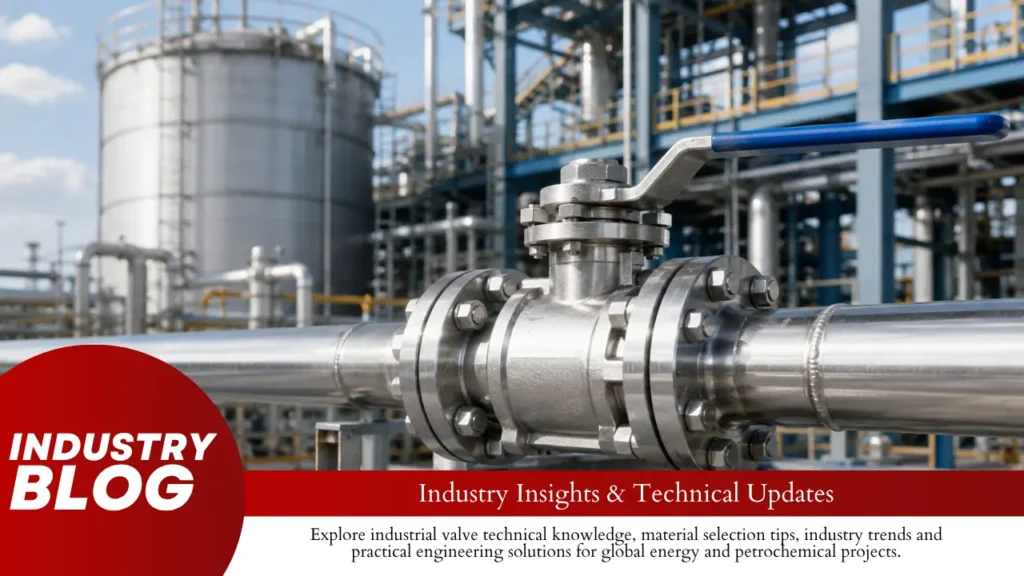
For clean methanol near room temperature, start with a carbon steel or 316 stainless steel ball valve, a PTFE-family soft seat, and an O-ring compound specifically confirmed for methanol. For colder service, high differential pressure, contaminated methanol, fire-critical isolation, or automated ESD duty, the specification must change. Do not approve a valve only because the datasheet says “316 SS + PTFE + Viton.” Pure Methanol Property Typical Value Valve Relevance Density at 20°C ≈ 792 kg/m³ Flow, loading and mass calculations Viscosity at 25°C ≈ 0.544 mPa·s Methanol is a low-viscosity liquid Vapor pressure at 20°C ≈ 12.8 kPa absolute Important for flashing during throttling Boiling point at 1 atm ≈ 64.6°C Important for warm service and pressure drop Freezing point ≈ -97.6°C The fluid may remain liquid below the safe temperature of the valve Thermal expansion coefficient at 20°C ≈ 0.00149/°C Important for trapped body-cavity pressure Closed-cup flash point ≈ 12°C Fire risk exists near normal ambient temperature Flammable range in air ≈ 6.0–36.5 vol.% Wide combustible vapor range Autoignition temperature ≈ 470°C Different from flash point These values are for pure methanol. Water, hydrocarbons and process contaminants change the fluid properties and can also change the correct metal, seat and elastomer choice.[1] Methanol Institute also states that its compatibility data should be treated as a starting point and checked against the actual service conditions.[2] Actual Service Good Starting Point Do Not Approve Until You Check Clean methanol, 0–40°C, moderate pressure Carbon steel or 316 SS + PTFE-family seat Exact O-ring, seat pressure-temperature rating Methanol with water/chlorides 316/316L often becomes more useful Actual contaminant concentration About -40°C Low-temperature body and qualified seals Body toughness, O-ring, packing, actuator torque -50°C and below Purpose-designed low-temperature valve ISO 28921-1 where applicable Large valve or high differential pressure Trunnion-mounted design may be better Torque and seat design Fire-critical isolation Fire-tested valve API 607 / ISO 10497 certificate scope Continuous throttling V-port/control ball valve Cv, vapor pressure, flashing, cavitation Send These Service Conditions to the Valve Supplier Information What to Provide Why It Changes the Valve Methanol concentration Example: 99.85%, 80%, recovered methanol Changes seal and corrosion conditions Water content Actual percentage where known Can change corrosion and freezing behavior Other chemicals Chlorides, acids, gasoline, oils, catalyst residue A seal suitable for neat methanol may fail in the mixture Solids Clean fluid or particle-containing fluid Particles can scratch the ball and cut soft seats Operating temperature Minimum, normal and maximum Affects body toughness, seals and torque Design temperature Minimum and maximum design values Used for material and pressure-boundary checks Line pressure Normal and design pressure Controls body pressure rating Differential pressure Maximum pressure difference when opening/closing Strongly affects seat load and actuator torque Cycles Example: 2/year, 10/day, 100/day Changes seat and packing wear Standby time Days, months or years without movement Can increase breakaway torque Valve duty Isolation, ESD or flow control Changes valve and actuator design Other fluids Hydrotest water, flushing fluid, cleaning chemicals These fluids also contact the seals Maximum differential pressure is especially important. A valve with 40 bar upstream and 35 bar downstream sees only 5 bar differential pressure. A second valve with 40 bar upstream and 0 bar downstream sees 40 bar differential pressure. Both are in a 40 bar system, but the second valve may require much more operating torque. Carbon Steel, 316 SS, or Low-Temperature Steel? Body Material Where It Makes Sense Main Limitation ASTM A216 WCB Clean methanol at suitable temperatures Low-temperature toughness must be checked ASTM A105 Forged carbon-steel valves for clean methanol Same temperature and contamination checks apply 304/304L General stainless construction Less chloride resistance than 316 316/316L Water/chloride contamination, clean-process service, cold service Higher cost does not automatically mean better service life ASTM A352 LCB/LCC Low-temperature cast-steel designs Actual impact-test and MDMT limits still need verification Methanol Institute gives favorable neat-methanol compatibility ratings to common carbon-steel valve materials including A105, WCB and LCB.[3] This is why 316 stainless steel should not be specified automatically for every methanol line. 316/316L becomes more useful when water or chlorides are present because its molybdenum content improves resistance to chloride-related pitting and crevice corrosion compared with 304.[3] For a wider comparison of carbon steel, stainless steel and duplex valve bodies, see the site’s ball valve material selection guide. For LCB and LCC, ASTM A352 lists -50°F (-46°C) as the usual minimum impact-test temperature.[4] This does not mean every LCC valve is automatically approved to -46°C, and it certainly does not mean an LCC valve is automatically suitable at -60°C. Check the actual material certificate, impact test, wall thickness and project code. Aluminum should be reviewed by exact alloy rather than accepted from a general “aluminum is compatible” statement. Methanol Institute notes that some aluminum alloys can be attacked and that contamination can make the problem worse.[3] PTFE, RPTFE, PEEK, or Metal Seat? Seat Good Fit What to Verify Virgin PTFE Clean methanol, moderate pressure and temperature Creep and pressure-temperature limit RPTFE Higher seat load or wear than virgin PTFE Filler type and actual seat rating Modified PTFE Where lower creep or better dimensional stability is needed Manufacturer’s exact compound and rating PEEK Higher mechanical load or temperature Torque, leakage and pressure-temperature data Metal seat High temperature, abrasive particles, erosion or severe wear Leakage class and operating torque Methanol Institute rates PTFE favorably for neat methanol and lists it for ball-valve seats and seals.[5] PTFE’s main weakness in a ball valve is normally mechanical rather than chemical. Under continuous seat load it can creep or cold-flow. High pressure and higher temperature make this more important. The four failure modes worth checking are: Failure What Happens Typical Result PTFE creep The seat slowly changes shape under continuous load Lower sealing force or changed torque Extrusion Soft material is pushed into a clearance Seat damage or leakage Thermal movement Metal and polymer expand/contract differently Leakage or torque change at hot/cold conditions Particle damage Solids cut the seat or scratch the ball Permanent internal leakage path A soft-seated ball valve
How to Select a Ball Valve for Slurry Service | Solids, Full Bore, Seat Design
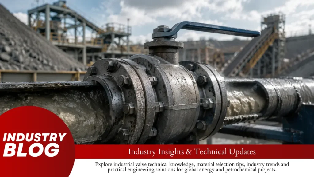
For on/off slurry service, select the valve from six items first: maximum particle size, particle hardness, solids concentration, settling behavior, maximum differential pressure, and required shutoff. Full bore is usually the safer starting point for isolation. Fine, soft solids may allow a polymer seat. Hard or abrasive solids may require metal seats and hard-facing. Fast-settling slurry needs cavity and seat-pocket control. High differential pressure requires a torque and erosion check before the actuator is selected. Main Slurry Problem Check First Hard abrasive particles Ball, seat, coating, seat geometry Large particles Minimum clear bore and closing path Fast settling Body cavity, seat pockets, flushing Sticky or scaling solids Scraping, flushing, shutdown cleaning High differential pressure Seat load, local velocity, valve torque Long shutdown Settling, hardening, restart torque Corrosive slurry Body, ball, coating, seals, temperature Specify the Slurry With Numbers Do not send an RFQ that only says “slurry service.” At minimum, give the valve supplier these values: solids concentration in wt.% or vol.% D50 D90 maximum particle size particle material or mineral particle hardness if known particle density or specific gravity normal and maximum flow upstream and downstream pressure maximum differential pressure normal, design, startup, and shutdown temperature cycles per day or year longest shutdown period These numbers tell the supplier whether the main risk is abrasion, particle trapping, settling, high torque, or chemical attack. Use wt.% and vol.% Correctly Weight concentration and volume concentration are not the same. Assume 100 kg of slurry contains 20 kg of mineral solids with a specific gravity of 2.65 and 80 kg of water. Item Example Value Total slurry mass 100 kg Solid mass 20 kg Particle specific gravity 2.65 Approx. solid volume 7.5 L Approx. water volume 80 L Solids by weight 20 wt.% Solids by volume About 8.6 vol.% So “20% solids” is not enough information. The RFQ should say either 20 wt.% or 20 vol.%. This is a calculation example only. Actual volume concentration changes with particle and liquid density. Use D50, D90, and Maximum Particle Size Together D50 is the size below which 50% of the stated cumulative particle distribution falls. D90 is the size below which 90% falls. The distribution may be based on mass, volume, or particle number, so the measurement basis should also be stated.[1] Laser diffraction is widely used for fine-particle sizing. ISO 13320 covers particle-size analysis by laser diffraction.[2] Useful conversions: 100 μm = 0.10 mm 500 μm = 0.50 mm 1,000 μm = 1.00 mm Do not select a valve from D50 alone. Particle Data Slurry A Slurry B D50 100 μm 100 μm D90 180 μm 600 μm Maximum particle 0.3 mm 2.0 mm Both slurries have the same D50, but Slurry B contains much larger particles. A 2 mm particle creates a very different closing problem from a 0.3 mm particle because it has a greater chance of becoming trapped between the ball and seat. Check Particle Hardness and Shape Hard particles can damage polymer seats, metal seats, and the ball surface. Common abrasive solids include: quartz silica sand ore particles ash metal oxides catalyst particles mineral tailings Fine particles are not automatically easy service. Small hard particles can remain suspended and repeatedly enter the sealing area. Angular particles usually cut a surface more aggressively than rounded particles of similar size. ASTM G75 provides the Miller Number for comparing slurry abrasivity and the SAR Number for comparing how materials respond to a particular slurry.[3] Check What Happens When Flow Stops For settling slurry, normal flowing conditions may not be the worst condition. Check whether the solids: settle within minutes or hours remain loose after settling compact into a dense bed form scale crystallize harden when dry Particle density, size, liquid viscosity, and particle shape all affect settling behavior.[4] Compare two valves carrying the same slurry: Valve A: operates every 4 hours. Valve B: may remain closed for 30 days. Valve B may have fewer annual cycles but a harder first movement because solids have had much more time to settle, compact, or crystallize. Keep Velocity Between Settling and Erosion Slurry velocity has two opposite risks: too high: more erosion too low: more settling There is no single correct velocity for every slurry. The acceptable range changes with particle size, particle density, solids concentration, pipe diameter, liquid properties, and how thick the slurry is. High local wear is most likely where flow: passes through a smaller opening changes direction hits a seat edge passes a partly open valve expands after a restriction Flow Condition What the Valve Sees Well suspended Solids remain distributed through most of the pipe. Uneven suspension More solids travel near the bottom. Moving solids bed A dense layer moves along the pipe bottom. Settled bed Solids stop moving and accumulate. A valve closing through a settled bed has a much higher chance of trapping solids than a valve closing through a well-suspended slurry. Use Full Bore for Isolation For on/off slurry isolation, full bore is usually preferred because it gives solids a larger and less restricted path. The effect of bore reduction is larger than it first appears. Bore Diameter Approx. Flow Area Relative Velocity at the Same Flow Rate 100 mm 7,854 mm² 1.00× 80 mm 5,027 mm² 1.56× Reducing a circular bore from 100 mm to 80 mm cuts flow area by about 36%. At the same incompressible volumetric flow rate, velocity through the 80 mm opening is about 56% higher. This does not mean every 80 mm bore will erode quickly. It shows why actual bore diameter matters in abrasive service. Do not rely only on “full port” or “full bore.” For piggable or coarse-solids service, specify: DN or NPS pipe schedule actual pipe ID required minimum clear valve bore The dimensional difference between full-bore and reduced-bore ball valves should be checked from the actual bore, not only nominal valve size. Full bore does not stop solids from entering the seat pockets or body cavity. Choose Polymer or Metal Seats by Wear Risk Seat Type
What Should Be Checked Before the First Operation of a Large Ball Valve? | Shipping Locks, Lubrication, Alignment
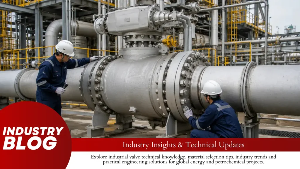
Before the first operation of a large ball valve, check the shipping restraints, bore and pipeline cleanliness, piping alignment, supports, actuator connection, travel stops, lubrication points, actuator supply, body-cavity fittings, valve position, and operating torque. A normal ball valve travels about 90° from fully closed to fully open. If it stops partway, makes a grinding noise, pulls on the pipe or actuator bracket, or needs much more torque than expected, do not force it. Find the cause first.Also record the pressure, actuator supply, opening time, closing time, and torque where available. Those numbers give you a useful reference for later maintenance. Isolate All Energy Before anyone works around the valve, make sure nothing can move unexpectedly and no stored pressure can be released. Block remote OPEN and CLOSE commands. Isolate electrical power where required. Isolate pneumatic or hydraulic supply where required. Check for stored pressure in accumulators. Account for stored spring energy in spring-return actuators. Confirm the required pipeline pressure condition. Treat the body cavity as pressurized until it has been safely checked. A pipeline gauge showing 0 bar only tells you what is happening at that gauge point. It does not prove that the valve body cavity, actuator cylinder, accumulator, or connected tubing is also at 0 bar. In U.S. workplaces, OSHA 29 CFR 1910.147 requires control of hazardous stored or residual energy during covered servicing and maintenance work.[1] Never put a hand, cloth, camera, or tool inside the bore while the actuator can move. Verify the Valve and Service Data Start with the nameplate and compare it with the approved datasheet and piping documents. The goal is simple: make sure the valve installed in the line is the valve the project actually called for. Check What to Confirm Tag Correct valve for the line Size For example NPS 12 / DN300, NPS 24 / DN600, or NPS 36 / DN900 Pressure class Matches the project specification Body material Matches the datasheet Seat type Soft seated or metal seated End connection Flanged or butt welded Actuator Correct model and fail action Pressure Actual upstream and downstream pressure Temperature Within the valve design condition Common pipeline-valve pressure classes include ASME Class 150, 300, 600, 900, 1500, and 2500. These class numbers are not fixed pressure values. The allowable pressure still depends on material and temperature. ASME B16.34 covers pressure-temperature ratings, materials, testing, dimensions, tolerances, and marking for valves within its scope.[2] ISO 14313:2025 applies to pipeline valves in ASME Classes 150, 300, 600, 900, 1500, and 2500 and covers design, manufacturing, materials, welding, assembly, testing, documentation, and process control.[3] Also identify whether the valve is floating or trunnion mounted. The difference between floating and trunnion-mounted ball valves affects how pressure loads the ball and seats. Seat construction matters too. Soft-seated and metal-seated ball valves do not respond the same way to dirt, temperature, and surface damage. Soft seats, in particular, can be damaged by sharp construction debris. Calculate Differential Pressure Use the upstream and downstream readings together. Differential pressure is the difference between them. Upstream Downstream Differential Pressure 100 bar 100 bar 0 bar 100 bar 95 bar 5 bar 100 bar 0 bar 100 bar The upstream gauge reads 100 bar in all three cases, but the load on the valve is not the same. Use the real differential pressure when checking actuator sizing and operating torque. Remove Shipping Restraints Large valves and actuators are often secured for transport. Before the first stroke, look for anything that was fitted only to stop movement during shipping. transport pins locking bolts steel brackets tie bars temporary supports protective blocks actuator transport restraints Do not remove a part just because it looks temporary. A permanent travel stop, valve lock, actuator lock, or structural bracket can look very similar. Use the valve drawing, actuator manual, packing drawing, or warning tag to identify the part before removing it. If a transport restraint is left in place, the actuator can push against a solid stop. That can damage the coupling, key, gearbox, actuator, or electric motor. Inspect the Bore and Ball The bore should be empty and clean before the ball moves across the seats. Remove: plastic covers wood foam tape desiccant bags cleaning cloths loose hardware Then check the ball and visible seat area for: weld spatter metal chips hard particles rust dents deep scratches Where the damage sits matters. A deep scratch across the seat contact path is more serious than a light mark outside the sealing area because it can create an internal leak path. Do not use wire brushes, abrasive paper, steel scrapers, or screwdrivers on the sealing surface unless the valve manufacturer allows it. Clean the Pipeline A new valve can be damaged during its first closing stroke if the pipeline still contains construction debris. Look for: weld slag grinding dust rust scale sand metal chips welding wire paint flakes gasket fragments nuts and bolts Do not rely only on a note saying the line was flushed. Check the actual result through: flushing discharge temporary strainer condition filter or screen condition collected debris visual bore inspection where possible Many ball valves are kept fully open during pipeline flushing so debris passes through the main bore instead of being dragged across the seat. Use the position specified by the valve manufacturer. If welding, grinding, cutting, or pipe modification took place after the last flush, check the line again. Remove Hydrotest Water Hydrotest water can remain in places that are not obvious from the outside. Check: the body cavity drain passages low points instrument tubing Remove or dry it as required by the project. Water left behind can lead to corrosion, freezing damage, or process contamination. Check Piping Alignment and Support The valve should fit the piping. The piping should not be pulled into position through the valve. Check: flange faces are aligned bolt holes line up pipe centerlines match the valve is not being pulled sideways supports carry the intended weight the actuator is not twisting the valve body Do
Why Does a Metal-Seated Ball Valve Leak More After Repeated Cycling? | Coating Wear, Lapping, Thermal Distortion
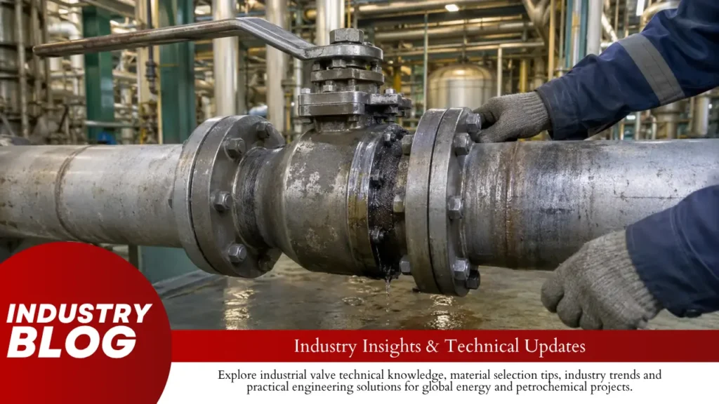
When a metal-seated ball valve starts leaking more after repeated cycling, the problem is usually at the ball-to-seat contact. The sealing surface may be scratched or worn, the coating may be damaged, the seat may no longer load the ball in the same way, or the ball may no longer return to exactly the same closed position. The leakage pattern often gives the first useful clue: did it rise slowly, appear suddenly, show up only when hot, happen mainly in one pressure direction, or begin right after maintenance? Leakage Pattern Most Likely Areas to Check First Slow increase over many cycles Coating wear, abrasion, erosion, loss of seat load Sudden increase Deep scratch, trapped particle, coating spall, stuck seat Leakage mainly when hot Thermal distortion, changing seat load, thermal interference Leakage after overhaul Ball/seat matching, actuator travel, assembly contamination Leakage mainly in one direction Pressure-assisted seat loading or one-sided damage Leakage and torque both rise Galling, deposits, rough coating, excessive local load In this article, leakage means internal seat leakage: fluid is getting through the closed valve between the ball and seat. Leakage from the stem packing, body joints, or flanges is a different problem. Start With the Leakage Pattern A cycle count by itself says very little. The same number of cycles can mean mild service in one plant and severe service in another. Operating Frequency Cycles per Day Approx. Cycles per Year 1 cycle every 8 hours 3 1,095 1 cycle per hour 24 8,760 1 cycle every 10 minutes 144 52,560 1 cycle per minute 1,440 525,600 A valve cycling once per minute can exceed half a million cycles per year. Even a very small amount of wear on each cycle can add up quickly at that frequency. But high cycle count does not automatically mean high damage. A valve completing 100,000 cycles in clean gas at stable temperature may still see less sealing damage than a valve completing 5,000 cycles in hot fluid carrying catalyst fines under high differential pressure. When leakage starts to rise, four operating details deserve attention first: differential pressure while the valve is opening and closing; temperature and temperature change during each cycle; solid-particle content and particle hardness; how long the valve spends partly open. These same points matter when specifying a valve for hot service. The high-temperature metal-seated ball valve guide covers them in more detail. Check the Seal Band The shutoff seal is not created by the whole ball surface. What matters most is the narrow circular band where the seat actually touches the ball. On inspection, look at whether that band is: continuous around the full seat; in the expected position; even in width; free from grooves that cross from one side to the other; free from isolated high-load areas. A surface can look polished and still leak. Under magnification, metal surfaces are made up of microscopic high points and valleys, so the true contact area is smaller than the area that appears to be touching.[1] That is why a small scratch can matter more than its appearance suggests. If the groove crosses the full sealing band, it can connect the high-pressure side with the low-pressure side and form a direct leak path. When the valve is dismantled, compare the scratch direction with the contact band. A large mark outside the sealing area may matter less than a narrow groove running straight across it. Check the Coating A hard-coated ball should not be judged only by how much of the surface still looks shiny. Look for: local coating loss; small pits; microcracks; flakes or chipped areas; exposed base metal; rough zones; uneven polishing; corrosion around damaged areas. Many tungsten-carbide surfaces are cermets. In simple terms, hard carbide particles sit inside a metallic binder. Research on WC-Co materials shows that the cobalt binder helps hold carbide grains together during sliding contact.[2] This matters in real service because the carbide does not have to become “soft” for the coating to fail. The binder can wear or corrode, carbide particles can pull out, or the coating can lose support from the base metal underneath. How the coating was applied and finished matters too. NIST thermal-spray research shows that process conditions can change coating structure and properties such as porosity, hardness, and bonding.[3] So two balls both described as “tungsten carbide coated” can perform differently if their coating thickness, porosity, bond quality, surface finish, substrate preparation, or grinding quality differs. For a repair decision, the useful questions are practical: How much coating remains? Is the coating still bonded? Has the base metal been exposed? Is the damage shallow enough to remove without changing geometry? Is the same damage likely to happen again in the same process? Separate Abrasion, Galling, and Erosion Abrasion, galling, and erosion can all damage a metal seat, but they do not point to the same root cause. Damage Type What Usually Causes It What It Often Looks Like Abrasion Hard particles trapped between ball and seat Directional scratches or grooves Galling Loaded metal surfaces sticking and tearing during sliding Rough, smeared, transferred metal Erosion High-velocity fluid or entrained particles Material loss near a jet or throttling area Abrasive damage depends on more than how much solid material is present. Particle hardness, shape, size, and the load pressing the particle between the ball and seat all affect the result. A small amount of hard angular debris can be more damaging than a larger amount of soft powder. If loose debris rolls or slides between the ball and seat, the process is often called three-body abrasion: the ball is one surface, the seat is the second, and the particle is the third body. Galling comes from a different mechanism. NIST describes it as severe sliding wear involving surface roughening, plastic deformation, fracture, and material transfer.[4] When galling develops, closing torque may rise because the surfaces become rougher and friction goes up. Erosion often takes over after a leak path already exists. A narrow groove can focus the flow into a
What Causes Ball Valve Seat Extrusion at High Pressure? | Polymer Clearance, Differential Pressure, Temperature
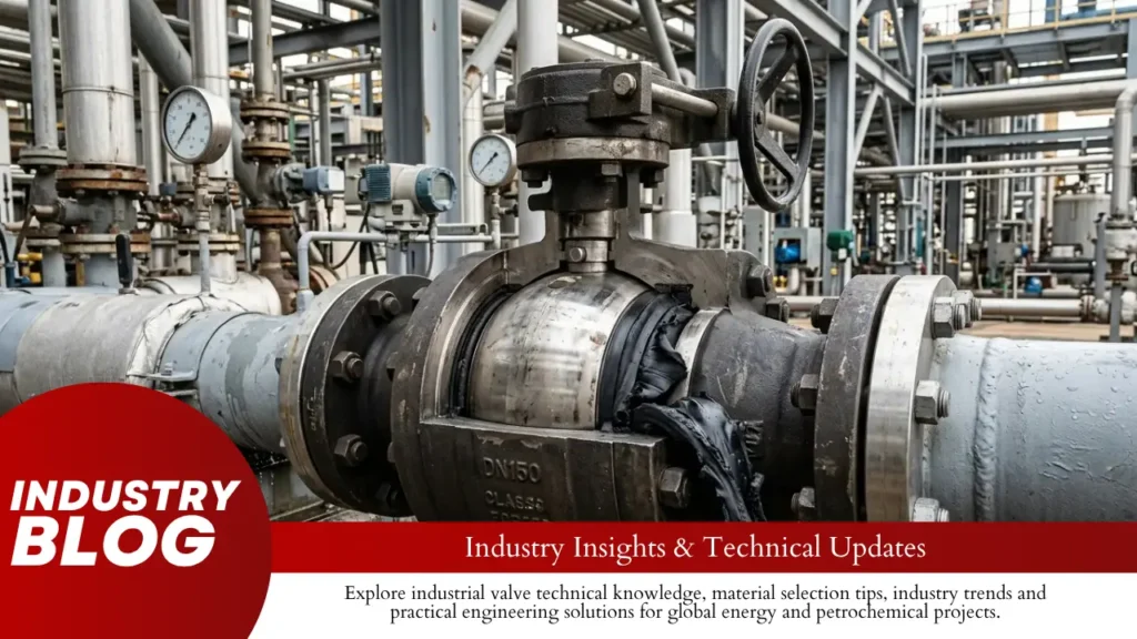
Ball valve seat extrusion usually starts when differential pressure pushes PTFE, RPTFE, PEEK or another polymer into a gap that does not give the seat enough support. When checking a failed valve, start with three things: the real pressure difference across the seat, the largest gap that exists when the valve is hot and pressurized, and whether the seat material can hold its shape under that load for the required time.The damage itself often gives useful clues. A thin lip pushed into a metal clearance strongly points to extrusion. A seat that stays flattened is more likely dealing with creep or too much compression. If the downstream seat of a floating ball valve is much worse than the upstream seat, downstream seat load should be checked first. If both seats are damaged, body-cavity pressure or reverse pressure also needs attention. Find the Gap Where the Polymer Moved Before deciding whether PTFE, RPTFE or PEEK is the problem, look at where the material actually went. Common extrusion paths include: between the seat outside diameter and the seat pocket; between the polymer seat and metal retainer; behind the seat; between a polymer insert and metal carrier; beside the seat edge near the valve bore. Follow the pressure direction. The first polymer edge that loses full metal support is usually the area worth checking most closely. A thin lip pushed into that gap is not the same as ordinary wear. Extrusion moves material into a space. Erosion removes material from the seat. Check the Hot Gap, Not the Drawing Gap The clearance shown on a drawing is only the starting point. The seat may see a different gap once the valve is assembled, pressurized and hot. The operating gap can change because of: seat OD and ID tolerance; seat thickness tolerance; seat-pocket diameter; retainer dimensions; ball diameter; seat-carrier dimensions; pressure-induced movement of metal parts; different thermal expansion of polymer and metal; assembly preload. Small changes are easy to ignore when looking at one part, but several changes can stack together. For example, if three dimensions each move only 0.02 mm in the unfavorable direction, the combined dimensional change can reach 0.06 mm. That is still a small number, but it can matter when the unsupported edge beside the seat is only a fraction of a millimetre wide. The same issue applies to a nominal gap. If an unsupported gap starts at 0.05 mm and tolerance, heat or pressure movement adds another 0.05 mm, the available extrusion path has doubled. These figures are illustrative, not universal valve tolerances. The value that matters is the worst operating clearance for the actual valve. Use Differential Pressure, Not Line Pressure For a closed valve, upstream pressure by itself does not tell you how hard the seat is being loaded. Upstream Downstream End-to-End ΔP 200 bar 180 bar 20 bar 200 bar 0 bar About 200 bar The upstream gauge reads 200 bar in both cases. The second condition, however, has about 10 times the end-to-end differential pressure. Pressure-generated force follows: Force = Differential Pressure × Effective Pressure Area The effective pressure area comes from the valve and seat geometry. It should not automatically be treated as the valve bore area. For illustration, a 10 MPa differential acting over a circular effective diameter of 25 mm gives an area of about 491 mm² and a force of about 4.91 kN. Illustrative Effective Diameter Area Force at 10 MPa 25 mm 491 mm² 4.91 kN 50 mm 1,963 mm² 19.63 kN 75 mm 4,418 mm² 44.18 kN These are pressure-area examples, not valve ratings. The useful point is the change in force: when effective diameter doubles, area and pressure force increase by about four times. This is also why a ball valve leaking at low differential pressure needs a different diagnosis from a valve damaged after a large ΔP event. One gauge reading does not show the full seat-loading condition. Do Not Read Pressure Class as a Seat Limit Pressure class, shell strength and polymer-seat life are different checks. ASME B16.34 covers pressure-temperature ratings, materials, dimensions, tolerances, examination, testing and marking for valves within its scope.[1] For a soft-seated ball valve, check three separate limits: Pressure boundary: whether the body and pressure-containing parts can safely hold the pressure. Shutoff: whether the seat can achieve the required leakage performance at the actual differential pressure. Seat life: whether the polymer can keep its shape after pressure, temperature, time and cycling. ISO 17292:2015 also covers metal ball valves as complete valve assemblies and includes material, inspection and testing requirements.[2] A high pressure class does not mean every polymer seat can run at the class maximum pressure and the seat’s highest temperature at the same time. For elevated-temperature service, use the rating for the actual body material, pressure class and seat configuration. The site’s ball valve pressure-class selection at elevated temperature explains why Class 150, 300 or 600 is not a fixed psi value. A Floating Ball Usually Loads the Downstream Seat Harder A floating ball can move slightly between the two seats. Once the valve closes and differential pressure builds, the ball is pushed toward the downstream seat. That means the downstream seat can carry far more load than the upstream seat. If the downstream seat is heavily damaged while the upstream seat still looks relatively normal, check: actual pressure direction; maximum ΔP; ball movement; downstream seat support; ball diameter; seat interference; contact-band width. A soft-seated floating ball valve uses this pressure-assisted downstream sealing action. The contact mark left on the removed seat is useful. A narrow, deeply compressed band suggests the load was concentrated over a small area. If the band is uneven around the circumference, check misalignment, dimensional variation, ball runout or debris before blaming the polymer alone. Larger Floating Valves Can Create Much Higher Seat Force Two valves can run at the same pressure and still place very different loads on their seats. In otherwise similar floating-ball designs, a larger valve usually has a larger projected pressure area.
Why Does a Ball Valve Leak at Low Pressure
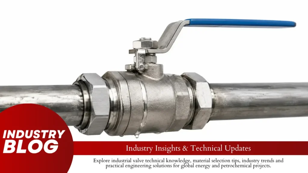
A ball valve that leaks at low pressure but seals better as pressure rises usually has one of four problems: the valve does not have enough seat force at low differential pressure, the seat or ball is damaged, a movable seat cannot move freely, or the ball is not reaching its full closed position.The first thing to check is not the pressure shown on one gauge. What matters is the pressure difference across the closed valve. If upstream pressure is 10 bar and downstream pressure is 9.9 bar, the valve sees only 0.1 bar ΔP. On the same effective pressure area, 0.1 bar produces only one-hundredth of the pressure force produced by 10 bar. If the seat is worn, dirty, deformed, or not moving properly, that lower force can make the leak show up. Safety: Do not loosen valve parts while the system is pressurized. Isolate and safely release stored pressure before removing an actuator, opening the body, or servicing seals. OSHA requires hazardous stored energy to be controlled during maintenance where unexpected release could cause injury.[1] Check Differential Pressure First Upstream pressure by itself does not tell you how much pressure is actually acting across the closed valve. ΔP = upstream pressure − downstream pressure Useful conversions: 0.1 bar ≈ 10 kPa ≈ 1.45 psi 0.5 bar ≈ 50 kPa ≈ 7.25 psi 1 bar = 100 kPa ≈ 14.5 psi 10 bar = 1,000 kPa ≈ 145 psi Upstream Downstream ΔP 1.0 bar 0 bar 1.0 bar 5.0 bar 4.5 bar 0.5 bar 10.0 bar 9.9 bar 0.1 bar 10.0 bar 10.0 bar 0 bar The last two rows show why line pressure can be misleading. A system may be running near 10 bar while the valve itself sees very little differential pressure. The same thing happens during pressure equalization. If upstream pressure stays at 5 bar while downstream pressure rises from 0 to 4.9 bar, ΔP falls from 5 bar to 0.1 bar—a 98% reduction. If the leak gets worse as ΔP drops, note that before taking the valve apart. That pattern helps narrow the fault quickly. Find the Leak Path Before checking seats or actuators, confirm where the fluid is actually going. Leak Type Typical Location Check First Internal leakage Upstream to downstream through closed valve Seat, ball, seat loading, travel Stem leakage Around stem or packing Packing and stem seals Body leakage Body joint, flange, thread, vent, drain Gasket, seal, bolting, pressure boundary These are different problems and should not be treated the same way. A leak through the closed valve points toward the ball, seat, seat loading, or travel. Fluid coming out around the stem or body points toward the external sealing parts instead. ISO 15848-1 deals with external leakage from valve stem or shaft seals and body joints in relevant valve applications.[2] If the leak location is uncertain, use a stem-leak vs. seat-leak check before removing the valve. Identify the Valve Type Floating-ball and trunnion-mounted valves do not build sealing force in exactly the same way. Knowing which type you have changes what should be checked first. Valve Type What Moves Low-ΔP Check Floating ball Ball can move slightly toward downstream seat Seat preload and downstream seat condition Trunnion ball Ball is supported; seats normally move Seat springs, seat friction, rear seals, seat movement In a floating soft-seated ball valve, upstream pressure can push the ball toward the downstream seat. In a soft-seated trunnion ball valve, the ball is supported, while spring-loaded seats move toward it. So if a floating valve leaks mainly at low ΔP, look closely at seat preload and the downstream sealing surface. On a trunnion valve, seat movement, spring condition, and friction also deserve attention. Compare Seat Force at Different ΔP The effect of pressure is easier to see with numbers. Assume a hypothetical effective pressure area of 20 cm², or 0.002 m². ΔP Pressure Force on 20 cm² 0.1 bar 10 kPa 20 N 0.5 bar 50 kPa 100 N 1 bar 100 kPa 200 N 5 bar 500 kPa 1,000 N 10 bar 1,000 kPa 2,000 N The table uses force = pressure × area. It is only an example, not a calculation for a specific valve. Actual seat force depends on valve geometry and the real effective pressure area. What matters here is the scale of the change: increasing ΔP from 0.1 bar to 10 bar increases pressure-generated force on the same area by 100 times. If a valve becomes tight only after ΔP rises sharply, the higher pressure is hiding the problem rather than fixing it. The next step is to find out why the seat needs that extra force. Check Seat Preload Seat preload is the force already pushing the seat against the ball before process pressure adds much more load. Loss of preload is more likely when: The valve used to seal at low ΔP but no longer does. The leak becomes much smaller as ΔP rises. The seat looks flattened or permanently compressed. The valve has spent long periods at elevated temperature. The seat has seen many operating cycles. An incorrect replacement seat has been fitted. Soft polymer seats can slowly change shape under load. The seat may still look usable but no longer press against the ball with the same force it had when new. Before replacing it, inspect the ball as well and look for the reason the preload was lost. Fitting another seat without correcting the cause can lead to the same leak again. Inspect the Seat and Ball When the valve is opened for inspection, focus on the sealing band rather than every cosmetic mark. What You Find Likely Meaning Narrow groove across seat Hard particle dragged across sealing surface Flattened seat area Long-term compression, creep, or excessive loading Missing seat material Erosion, cutting, chemical damage, or excessive heat Particles embedded in seat Dirty pipeline or contaminated process Scratch across ball sealing band Possible direct leakage path Uneven wear around seat Misalignment, body distortion, or uneven loading
Why Does a Ball Valve Jam After Shutdown
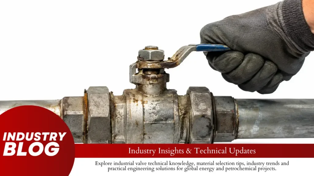
A ball valve usually jams after shutdown because the torque needed to start it has increased, or the actuator can no longer deliver enough torque. In practice, the quickest clues are pressure, temperature, what happened to the process fluid while the line was stopped, and whether the actuator is actually turning the valve.A standard ball valve moves through about 90° from fully closed to fully open. Where it becomes hard to turn during that 90° travel can tell you a lot about what is wrong. Symptom Most Likely Causes First Check Very hard only at the start Pressure load, seat friction, deposits Upstream/downstream pressure Hard only after cooling High viscosity, crystals, solidification Shutdown temperature and fluid properties Hard after heating Trapped liquid, thermal expansion, pipe movement Cavity condition and pipe temperature Hard through most of the 90° stroke Deposits, tight packing, body distortion Stem friction and contamination Stops at the same angle every time Foreign object, damaged seat, mechanical failure Internal and drive components Actuator moves but the valve does not Coupling, gearbox, adapter, or stem failure Actuator-to-stem drive path Pressure Across the Valve A floating ball valve allows the ball to move slightly between the seats. When pressure is higher on one side, that pressure pushes the ball toward the downstream seat. That helps the valve seal, but it also creates more friction. This becomes important after shutdown. For example, the valve may close while pressure is almost equal on both sides. During shutdown, the downstream side is depressurized but upstream pressure remains. When the valve has to open again, it is now working against a much larger pressure difference. Pressure load is a strong suspect when: the valve becomes harder as differential pressure increases; it becomes easier after pressure is safely equalized; it operates normally when depressurized; most resistance occurs during the first few degrees of movement. The first few degrees matter because a stationary valve can need more torque to start moving than it needs once the ball is already turning. That starting force is commonly called breakaway torque. If the valve is very tight at first and then moves freely through most of its 90° travel, pressure load, seat friction, or deposits around the closed position are more likely than a blockage running through the whole valve. The different torque points are covered in the ball valve torque curve guide. Pressure Trapped Inside the Valve A line can show little or no pressure while liquid is still trapped inside the valve body. The reason is simple: the ball sits inside a body that is larger than the flow bore. Depending on the seat design and valve position, fluid can remain in the space around the ball after the main line has been drained. That trapped fluid creates a different issue from differential pressure across the valve. A nearby pressure gauge showing zero does not confirm that every enclosed space inside the valve is also at zero pressure. If the trapped material is liquid and its temperature rises, the risk becomes more serious. Liquid is far less compressible than gas, so a liquid-filled cavity with little free space can develop a large pressure increase as the liquid expands. For valves within the scope of API Specification 6D, automatic cavity relief is required when liquid trapping is possible. For temperatures up to 250°F (121°C), the specified cavity relief pressure must not exceed 33% differential pressure above the valve pressure rating.[1] Cavity pressure may be controlled by self-relieving seats, a defined relief direction, or another engineered relief system. A vent or drain connection by itself does not prove that the valve automatically relieves cavity pressure. The seat arrangement matters, especially in trunnion designs. The article on pressure buildup inside a closed ball valve explains how trapped liquid, temperature, and relief direction interact. Fluid Becomes Thick or Solid Many shutdown problems come from the fluid rather than the valve itself. A product that flows normally while hot or moving can behave very differently after sitting still. What Happens to the Fluid Typical Effect on the Valve Viscosity rises Thick fluid increases resistance around the ball Wax or product solidifies The ball can become partly locked in place Resin or polymer cures Hard material bonds to internal surfaces Water or solvent evaporates Dry residue remains around the ball and seats Dissolved material crystallizes Hard crystals form at seats and cavity surfaces Heavy oils, wax-containing hydrocarbons, resins, fats, bituminous products, polymers, adhesives, and concentrated chemical solutions can all change significantly when temperature or flow changes. Another practical issue is that the valve cavity can hold process fluid even when the main bore looks empty. Material left around the ball may cool, harden, dry, or react while the system is stopped. If a valve works hot but jams after cooling, check the actual shutdown temperature against the fluid’s: viscosity-temperature curve; crystallization temperature; freezing point; pour point; solidification temperature; known precipitation conditions. Using more actuator torque does not remove hardened material. It only transfers more load into the stem, seat, coupling, and actuator. Crystals and Scale A fluid does not need to freeze completely to jam a valve. Dissolved material can leave the liquid and form hard crystals while the remaining fluid is still liquid. This often happens when a concentrated solution cools after shutdown. Crystals can build on the ball, seat edges, stem area, and cavity walls. The operating pattern is often gradual: the valve becomes a little harder after one shutdown, harder again after the next, and eventually needs enough force to crush or scrape through the deposit. Scale can also come from: mineral precipitation; evaporation; corrosion products; chemical reactions; changing fluid concentration. If flushing brings the valve back to normal but the same problem returns after every shutdown, the issue is usually the material being left inside the valve, not simply actuator size. Sand, Sludge, and Other Solids Particles that stay suspended while the line is flowing can settle once the system stops. Sand, rust, catalyst fines, mineral particles, pulp,
When Should Valve Sealant Be Injected
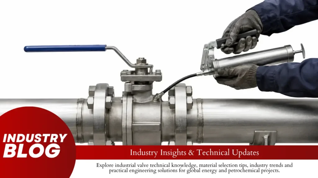
Use valve sealant only when the valve has an injection system made for the problem you are dealing with. In practice, that usually means minor seat leakage, certain stem leaks, or routine sealant service on valves that rely on injected sealant. If the problem is a cracked body, leaking flange, broken seat, actuator fault, or unexplained high torque, sealant is not the answer. What You Find What to Do Minor seat leakage Sealant may help if the valve has a seat injection system Minor stem leakage Use the stem injection system if the valve provides one Valve is becoming harder to turn Find the cause first; lubricant may be needed instead Lubricated plug valve due for service Follow the manufacturer’s sealant interval Flange, body, bonnet, or structural leak Do not treat it with normal valve sealant Leak returns sooner after each injection Plan inspection or repair instead of repeated injection Inject for Minor Seat Leakage Seat sealant is useful when the seat is still doing most of its job, but a small leak path has appeared between the seat and the ball or gate. Common causes include: Sand trapped between the seat and ball Rust or pipe scale Welding debris Hard process deposits Small scratches Minor seat wear A healthy seat makes continuous contact with the ball. Once a scratch cuts across that sealing band, fluid can pass through the small gap. If the valve has an approved seat-injection passage, sealant can fill that path and reduce the leakage. In the field, injection has a better chance of working when: The valve reaches its full closed position. The seat still contacts the ball. The leak is small and stable. The damage is limited to a scratch, small gap, or minor wear. The injection passage is open. Once the damage becomes mechanical rather than minor surface wear, the situation changes. A torn soft seat, badly eroded metal seat, deformed seat ring, damaged ball, or broken internal part cannot be rebuilt with sealant. Seat material also changes the way damage develops. PTFE, PEEK, and metal seats behave differently under temperature, particles, pressure, and wear. The differences are covered in this PTFE, PEEK, and metal seat comparison. If a ball valve leaks only when pressure comes from one side, do not assume both seats are bad. The cause may be one damaged seat, a rear seat seal, seat orientation, or the SPE/DPE arrangement. This one-direction ball valve leak diagnosis covers the main checks before sealant is injected. Inject for Some Stem Leaks Stem sealant only makes sense when the valve has a dedicated stem or packing injection point. Typical signs are: Liquid around the stem Drops below the packing area Gas detected around the stem Process residue under the gearbox or actuator Repeated fugitive-emission readings On many valves, the packing or stem seal is still the main long-term sealing part. The injected sealant works as a backup around small leakage paths. If the leak stops after injection, the worn packing underneath has not been restored to new condition. Gas leakage is different from a visible liquid leak because there may be nothing to see. ISO 15848-1 covers testing of external leakage from valve stem or shaft seals and body joints for valves used with volatile air pollutants and hazardous fluids.[1] Some lubricated plug valves work differently. On those designs, injected packing or sealant can be part of the normal sealing system, not just an emergency backup. Use Lubricant for Torque Problems A valve that is getting harder to turn may need attention, but that does not mean it needs sealant. Possible causes include: Dry or aged lubricant Deposits or dirt Corrosion Seat swelling Bearing damage Gearbox problems Actuator problems Mechanical jamming High differential pressure Breakaway torque is the turning force needed to start a stationary valve moving. If that force rises slowly over months or years, friction, deposits, or aging lubricant may be involved. A sudden change should be treated differently. For example, if the same valve suddenly requires about 2× its normal operating torque, that is a fault worth investigating. The 2× figure is an example of a major change, not a universal alarm limit. The cause may be a damaged part, foreign material, severe corrosion, abnormal pressure load, or a gearbox or actuator problem. Simply applying more force can make the damage worse. If torque is normal when pressure is equalized but rises sharply under full differential pressure, process pressure may be a major part of the problem. The trunnion ball valve maintenance guide covers lubrication, torque changes, and common internal problems. Match the Valve Design Sealant practice changes with valve design, so one rule does not fit every valve. Trunnion-mounted ball valves often have separate seat and stem injection systems, especially in larger pipeline sizes. Their internal layout can be seen in this guide to trunnion ball valve construction. A forged soft-seated trunnion ball valve may therefore include maintenance features that are not present on smaller floating valves. Floating ball valves use line pressure to push the ball toward the downstream seat. Many smaller floating designs have no field seat-sealant system. The practical differences are shown in the floating vs. trunnion ball valve comparison. Lubricated plug valves may use injected sealant as part of normal operation. API 6D requirements for hydrogen service specifically require the lubricant/sealant used in lubricated plug valves to be validated for the valve’s rated temperature range.[2] Gate valves are less predictable in this respect. Some have seat or stem injection fittings and some do not, so the exact model needs to be checked before any injection equipment is connected. Many butterfly, globe, check, control, and small ball valves have no field sealant-injection system at all. Do Not Inject for These Faults Normal valve sealant is not a repair for structural or major mechanical damage. A cracked body or bonnet Severe corrosion or wall loss A failed flange gasket A badly damaged seat A broken ball, gate, plug, or stem A gearbox failure An actuator failure
How Often Should Pipeline Ball Valves Be Exercised
For a normally static, non-regulated pipeline ball valve in clean, stable service, 6–12 months can be used as a maintenance planning range. That works out to about 1–2 planned checks per year. Where the valve has a critical isolation duty, handles dirty fluid, sits in a harsh environment, or needs closer monitoring, a 3–6 month range, or about 2–4 checks per year, may make more sense. These are planning ranges, not API requirements or universal industry rules. Valve condition Practical interval Approx. checks/year Clean, stable, non-regulated service 6–12 months may be used for planning 1–2 Critical or severe service 3–6 months may be justified 2–4 Frequently operated valve Use operating history and condition data Condition-based Valve showing abnormal torque, travel, leakage, or actuator faults Investigate and repair as required Do not rely on the calendar Regulated pipeline valve Follow the applicable legal interval As required by regulation Use These Five Inputs to Set the Interval The calendar is only one part of the decision. In practice, the interval should come from the items below, starting with anything that is mandatory. Input What to check Effect on the interval Regulation Mandatory inspection or operating interval Never exceed the legal maximum OEM and site procedure Valve manual, actuator manual, O&M procedure, safety-system test plan Use the specified interval if one is given Isolation duty What happens if the valve cannot close? Higher consequence normally needs closer verification Service condition Solids, wax, corrosion, water, temperature, flooding, salt, dust Faster deterioration may justify shorter checks Condition trend Torque, stroke time, leakage, actuator behavior, position feedback Worsening data requires investigation An ESD or SIS valve should not be put on a 3- or 6-month cycle just because it is used for emergencies. Its approved functional-safety and proof-test program comes first. IEC 61511 covers the specification, design, installation, operation, and maintenance of safety instrumented systems in the process industries.[1] If the valve already has a known fault, a shorter calendar interval is not the fix. Find the cause, repair it where needed, verify the result, and then decide how closely it should be watched. Choose Partial or Full Stroke Based on What You Need to Prove Test What it can show What it does not prove Visual inspection External leakage, corrosion, damage, access problems That the valve can move Partial stroke The valve and actuator can start moving through the tested travel Full travel or seat tightness Full stroke Complete mechanical travel Leak-tight shutoff by itself Position check Local and remote indication agree with field position Seat tightness Seat or leakage test Shutoff performance under the test conditions Future actuator reliability A conventional quarter-turn ball valve has about 90° of full travel. A 20° movement is about 22% of that travel. This is only a mathematical example; it is not a recommended partial-stroke setting. Partial stroke is useful when you want to confirm that the valve can start moving without fully shutting the line. It may expose a seized valve, actuator trouble, loss of instrument pressure, a control fault, a position-feedback error, or an unusually slow response. What it cannot tell you is whether the valve can finish the remaining travel or whether the seats will actually stop flow. A full stroke checks the whole movement. It is more likely to expose resistance near the closed position, incorrect stops, gearbox trouble, weak actuator output, or incomplete travel. Because full closure can disturb pipeline operation, it should only be done when the approved operating procedure allows it. Check Movement, Position, and Shutoff Separately Failure Typical signs Likely area to check Valve will not move High torque, actuator stall, no travel Seats, stem, bearings, gearbox, actuator Valve reaches position but leaks Flow continues after closure Seats, ball surface, debris, bypass path Valve moves but indication is wrong Local and remote positions disagree Limit switch, transmitter, coupling, wiring, SCADA A valve may complete its 90° travel and still leak through damaged or contaminated seats. That is why “closed,” “operable,” and “leak-tight” should not be treated as the same result. When the valve moves normally but fluid still passes through it, the next step is to work out where the leak is coming from. This ball valve leakage troubleshooting guide covers the main checks for stem leakage, seat leakage, and other common field symptoms. Shorten Checks for These Service Conditions Condition What it can do to the valve Wax or heavy deposits Increase resistance around the seats Sand, rust, or scale Abrade ball and seat surfaces Slurry or hard solids Increase erosion and seat damage Water or corrosive contamination Attack internal parts, stems, gearboxes, or actuators Salt or coastal exposure Accelerate external corrosion Flooding Damage gearboxes, switches, electrical parts, and valve-box access Rarely operated emergency isolation duty Provides little normal operating data before demand Two valves of the same size can behave very differently if one sees clean gas and the other sees wax, sand, water, or corrosive material. Service conditions matter because they affect the parts that actually move and seal. Valve construction matters too. The main differences are shown in this comparison of trunnion-mounted and floating ball valves. For example, a soft-seated trunnion ball valve may use SPE/SPE, DPE/DPE, or SPE/DPE seat arrangements. Seat direction affects sealing and how trapped cavity pressure is handled, so the exact valve drawing and manual matter during maintenance. Compare Torque Under Similar Pressure Conditions Breakaway torque is the torque needed to start moving a stationary valve. If it keeps rising under similar test conditions, something in the valve or drive train may be getting harder to move. Test Breakaway torque Change from baseline January, Year 1 720 N·m Baseline July, Year 1 790 N·m +9.7% January, Year 2 910 N·m +26.4% July, Year 2 1,080 N·m +50.0% Here, the valve still moves, but breakaway torque has increased by 360 N·m, or 50%. That is a clear reason to look at deposits, corrosion, stem friction, bearings, gearbox condition, seat damage, or contamination. It is not a universal failure limit. Pressure can change
Why Is a New Ball Valve Hard to Turn
A new ball valve is usually hard to turn for one of four reasons: new seat and stem-seal friction, high starting torque, pressure loading the seats, or stress added during installation. If the handle feels firm but moves smoothly, that may be normal. If it grinds, sticks at the same position, suddenly becomes tight after installation, or takes enough force to bend the handle, something needs checking. What You Notice Check First Hard before installation Seat friction, stem packing, lock, stop, storage condition Hard only when movement starts Breakaway torque Hard only under pressure Differential pressure and seat load Easy before installation, hard afterward Pipe alignment, connection load, body stress Hard at the same position every time Debris, seat damage, stop or mechanical interference Hard after actuator installation Coupling alignment, actuator output, mounting bracket Hard after several days of service Deposits, contamination, fluid condition, temperature Hard Before Installation If the valve is already firm before it goes into the pipe, pipe stress and system pressure are not the first things to blame. The resistance is coming from the valve itself. On a soft-seated ball valve, the seats press against the ball so the closed valve can seal. That contact naturally creates friction, even before the valve sees line pressure. The seat load needs to be high enough to seal, but not so high that friction and wear become excessive.[1] A firm new valve is usually less concerning when: the movement is smooth; there is no scraping or gritty feel; the valve reaches both intended stops; resistance is similar on repeated normal cycles. Before looking for an internal fault, check the obvious items. A locking tab, detent pin or transport restraint may still be engaged. The handle may also be catching on nearby hardware. Do not expect every new valve to become much easier after several cycles. Operating torque can rise or fall over time because of wear, contamination, deposits, packing condition and long periods without operation. Hard Only When Movement Starts Some valves need the most effort right at the start. The handle feels heavy for the first few degrees, then the movement becomes smoother. That usually points toward breakaway torque. Breakaway torque is the torque needed to get a stationary ball moving. At that moment, the valve has to overcome static friction at the seats, stem packing and thrust surfaces. Once the ball is already moving, the torque may be lower. For example, if one specific valve needs 30 N·m to start moving but 20 N·m during mid-stroke travel, its starting torque is 50% higher than its running torque. These figures are only a calculation example, not normal values for all ball valves. This matters when an actuator is selected. The actuator has to cover the highest torque the valve needs, not just the easier part of the stroke. The ball valve torque curve guide explains break torque, running torque and sizing margin in more detail. Hard Only Under Pressure A valve that turns normally with no pressure but becomes much harder once the line is pressurized is giving you a useful clue: look at the differential pressure across the valve. This matters especially on a floating ball valve. With the valve closed, pressure can move the ball slightly toward the downstream seat. The seat then presses harder against the ball, so more friction has to be overcome when the valve opens. Line pressure and differential pressure are not the same thing. Example 1: upstream: 150 psi; downstream: 0 psi; differential pressure: 150 psi. 150 psi is approximately 10.3 bar or 1.03 MPa. Example 2: upstream: 150 psi; downstream: 140 psi; differential pressure: 10 psi. 10 psi is approximately 0.69 bar or 69 kPa. The upstream pressure is the same in both examples, but the pressure difference across the closed valve is very different. These values only show the calculation and are not pressure ratings for a particular valve. Floating and trunnion-mounted valves also carry pressure loads differently. The site’s floating vs. trunnion ball valve comparison explains the structural difference. Never loosen, vent or partly dismantle a pressurized valve just to see whether the handle becomes easier. Hard After Installation If the valve was fine in your hand but becomes noticeably tighter after the piping is connected, start with the installation. The body does not have to look visibly bent. A relatively small external load can shift the alignment of the body, stem, ball and seats enough to increase operating torque. Check for: flanges that do not naturally line up; pipe being pulled into position through the valve; unsupported pipe hanging from the valve; a heavy actuator loading the stem sideways; excessive tightening of connections; thermal pipe movement after startup. A valve should sit between correctly aligned pipes. It should not be used as the part that forces the piping into position. The change in torque can be more useful than the final number itself. If the same valve requires 20 N·m before installation and 35 N·m immediately afterward under similar test conditions, torque has increased by 75%. That does not prove that 35 N·m is unsafe, but the increase is a strong reason to check alignment and installation load. The ball valve installation and post-installation testing guide covers useful checks before and after the valve enters the piping system. ASME B16.34 covers pressure-temperature ratings, materials, dimensions, testing and other requirements for many industrial metallic valves.[2] Hard After Threaded or Union Connections Are Tightened Threaded valves and plastic true-union valves can both become harder to turn after installation, but the way the load gets into the valve is different. With a threaded valve, excessive tightening or poor wrench placement can send twisting force through the body. Use the wrenching points and tightening method specified for that valve rather than holding the far end of the body and applying large torque through the whole valve. For PVC, CPVC and PP true-union valves, check: whether the pipe ends naturally line up; whether the pipe is pushing or pulling on the
