
The pressure behavior described below mainly applies to trunnion-mounted ball valves with spring-loaded moving seat rings. Floating ball valves use ball movement to load the downstream seat and should be checked separately.
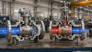
SPE vs DPE Under the Same Pressure
| Pressure Condition | SPE Seat | DPE Seat |
|---|---|---|
| Pressure enters from the pipe end | Moves toward the ball | Moves toward the ball |
| Cavity pressure becomes higher | Can move away from the ball | Moves more firmly toward the ball |
| Automatic relief through the seat | Yes, after the opening differential is reached | Normally no |
| Can one seat hold pressure from both sides? | Not as a lasting full-pressure barrier | Yes, subject to the approved design and test |
| Common complete arrangement | SPE/SPE | DPE/DPE |
| Common valve function | API-style DBB | DIB-1 |
| Main risk | Relief may enter an unsafe pipe end | Liquid pressure may remain trapped between the seats |
SPE and DPE describe one seat. DBB, DIB-1 and DIB-2 describe the complete valve. A supplier should not claim DIB performance only because DPE seats are installed. The seat arrangement, pressure direction and factory test must all match.
100 Bar Can Create 10–20 kN of Seat Force
The seat force comes from pressure acting over an effective ring-shaped area:
Seat force = pressure × effective pressure area
| Pressure | Effective Area | Calculated Force |
|---|---|---|
| 50 bar | 1,000 mm² | 5 kN |
| 100 bar | 1,000 mm² | 10 kN |
| 150 bar | 1,000 mm² | 15 kN |
| 100 bar | 2,000 mm² | 20 kN |
These are calculation examples, not valve ratings. The real effective area is set by the seat-ring diameters, rear-seal positions and internal pressure passages.
Doubling the pressure doubles the pressure-generated force. Doubling the effective area also doubles the force. This is why two seats of similar size can behave differently when their rear seals are installed at different diameters.
At low differential pressure, the springs provide most of the seat load. At higher pressure, fluid pressure adds more force. A DPE seat can therefore seal from both pressure directions, but it can still leak at low pressure if the springs, ball surface, seat surface or rear seals are damaged.
An SPE seat opens only after cavity pressure creates enough force to overcome:
- Spring preload
- Rear-seal friction
- Seat-to-ball friction
- Pressure acting in the closing direction
- Dirt or deposits behind the seat ring
The opening pressure and reseating pressure may differ. The test report should record both values instead of stating only “self-relief passed.”
At 100/80/20 Bar, Only the Right SPE Can Relieve
A closed valve may have three different pressures: left-side pressure, cavity pressure and right-side pressure.
| Left Side | Cavity | Right Side | Seat Pressure Difference |
|---|---|---|---|
| 100 bar | 50 bar | 0 bar | Right SPE sees a 50-bar opening differential |
| 100 bar | 80 bar | 20 bar | Right SPE sees 60 bar; left SPE remains pressure-loaded toward the ball |
| 100 bar | 110 bar | 90 bar | Left SPE sees 10 bar; right SPE sees 20 bar |
| 80 bar | 80 bar | 80 bar | No cavity-to-line differential |
In the 100/80/20-bar case, cavity pressure does not exceed the 100-bar left side. It can still relieve through the right SPE because the cavity is 60 bar above the right side.
Each SPE seat responds only to:
- Cavity pressure
- Pressure at its own adjacent valve end
- Its spring and friction forces
The seat does not compare both pipe pressures and actively choose the lowest side. The actual opening differential must be supplied or tested for the specific valve.
A 20°C Rise Can Add About 80 Bar in an Idealized Cavity
A body cavity may contain process liquid, hydrotest water, condensate, cleaning fluid or liquid entering through a leaking seat. A completely liquid-filled cavity can gain pressure quickly when heated.
A simple screening calculation is:
Pressure rise ≈ bulk modulus × volume expansion coefficient × temperature rise
Using an idealized water-like liquid near room temperature:
- Bulk modulus: 2.0 GPa
- Volume expansion coefficient: 0.0002 per °C
- No gas pocket
- No leakage
- No seat movement
- No valve-body expansion
| Temperature Rise | Idealized Pressure Rise |
|---|---|
| 5°C | 2 MPa, about 20 bar |
| 10°C | 4 MPa, about 40 bar |
| 20°C | 8 MPa, about 80 bar |
| 30°C | 12 MPa, about 120 bar |
These values show the risk of liquid trapping; they are not predictions for a real valve. Actual pressure depends on the fluid properties, gas volume, starting pressure, valve-body flexibility, seal compression and leakage paths.
API 6D Addendum 3 requires automatic cavity relief when liquid trapping is possible. For temperatures up to 250°F or 121°C, the cavity-relief pressure must not exceed a 33% differential above the applicable valve pressure rating.[1]
| Valve Rating at Temperature | 33% Differential | Arithmetic Upper Value |
|---|---|---|
| 100 bar | 33 bar | 133 bar |
| 160 bar | 52.8 bar | 212.8 bar |
| 250 bar | 82.5 bar | 332.5 bar |
The table only shows the arithmetic. The 33% figure is a maximum limit under the stated conditions, not a standard relief-valve setting. The final setting must also allow for relief-device tolerance, backpressure, pressure accumulation and the ratings of connected fittings and instruments.
API 6D also requires the manufacturer to determine whether liquid can be trapped with the valve open, closed or in both positions. Some valves use a hole through the ball or another internal pressure-balance passage. That feature must appear on the approved sectional drawing.
More causes and pressure patterns are covered in the guide to pressure buildup inside a closed ball valve.
SPE/SPE Relieves Pressure but Does Not Give Full DIB
An SPE/SPE valve has one self-relieving seat at each end. In a standard symmetrical design, either seat can become the pressure-side seat.
| Condition | SPE/SPE Response |
|---|---|
| Pressure comes from the left | Left SPE provides the main barrier |
| Pressure comes from the right | Right SPE provides the main barrier |
| Cavity pressure rises above the right side | Right SPE may open after its relief differential is reached |
| First seat leaks | Opposite SPE may hold temporarily, then relieve |
| Both pipe ends are depressurized | Cavity pressure may discharge through either SPE, depending on the design |
SPE/SPE is commonly used for API-style DBB because the valve can block pressure entering from either end and the cavity can be vented.
It should not be treated as DIB from one pressure source. If the first SPE leaks, the second SPE may initially hold cavity pressure, but it can open when its relief differential is reached.
SPE/SPE is suitable when:
- Automatic internal cavity relief is required
- Pressure may come from either valve end
- One main pressure barrier is acceptable
- Cavity fluid may safely enter an adjacent pipe
A forged soft-seated trunnion ball valve should be ordered with the exact SPE/SPE arrangement stated on the data sheet and sectional drawing.
DPE/DPE Gives DIB-1 but Needs Separate Relief
A DPE/DPE valve uses two seats that can be pressure-loaded from the line side or cavity side.
With pressure from the left:
- The left DPE provides the first barrier.
- If it leaks, pressure enters the cavity.
- Cavity pressure loads the right DPE toward the ball.
- The right DPE provides the second barrier.
When pressure comes from the right, the two seats exchange roles. This is why DPE/DPE is commonly used for DIB-1.
DPE/DPE is suitable when:
- Two tested barriers are required from either valve end
- One leaking seat must not pressurize protected equipment
- Reverse pressure is possible
- Metering or proving accuracy depends on tight isolation
- Cavity relief can be routed through a separate system
If liquid can be trapped, neither DPE seat normally opens to release it. The valve therefore needs an automatic cavity-relief path separate from the two seats.
For a large-valve example, see this DN600 PN63 DIB-1 trunnion ball valve project.
SPE/DPE Gives DIB-2 in One Direction
Assume the SPE seat is on Side A and the DPE seat is on Side B.
| Pressure Source | First Barrier | Second Barrier | Relief Path |
|---|---|---|---|
| Side A | Side A SPE | Side B DPE | Back toward Side A through the SPE |
| Side B | Side B DPE | Side A SPE may hold only until its relief point | Toward Side A when the SPE opens |
For the intended DIB-2 direction, the SPE normally faces the defined pressure source and the DPE faces the protected side.
If pressure reverses, the valve may still provide basic shutoff, but the same two-barrier DIB-2 function cannot be assumed.
The pressure direction must be checked for:
- Normal operation
- Reverse flow
- Hydrostatic testing
- Nitrogen purging
- Pig launching and receiving
- Pump or compressor shutdown
- Backflow from storage or process equipment
If leakage appears only after pressure is reversed, check the installed direction, seat arrangement and condition of both seats. See the one-direction ball valve leakage guide.
DBB, DIB-1 and DIB-2 Are Different Requirements
| Function | Common Seat Arrangement | What It Provides | Pressure Direction |
|---|---|---|---|
| API-style DBB | SPE/SPE | Blocking from both valve ends plus cavity bleed | Basic shutoff from either end |
| DIB-1 | DPE/DPE | Two barriers from one source | Either valve end |
| DIB-2 | SPE/DPE | Two barriers plus an SPE relief path | One specified source direction |
These are common arrangements, not automatic certificates. API 6D Addendum 2 also requires covered double-seated valves that seal against the pressure source with the upstream seat to have a drain or vent connector, except for its stated Annex M condition.[2]
A cavity connector allows draining, venting, pressure measurement or relief-device connection. A closed manual vent is not automatic pressure protection.
For an isolation assembly rather than a single valve, check the DBB valve assembly design guide.
OSHA uses a different DBB definition for permit-required confined-space isolation. It requires two in-line valves to be closed and locked or tagged, with the drain or vent between them opened and locked or tagged.[3]
A single API-style DBB ball valve does not automatically meet that OSHA definition.
A Relief Valve Needs Both a Set Pressure and Enough Capacity
A DPE/DPE cavity-relief system may use:
- A spring-loaded relief valve
- A pilot-operated relief device
- A return line to the pressure-source pipe
- A closed-drain connection
- A flare or recovery connection
- An approved pressure-equalizing system
| Relief Item | Question It Must Answer |
|---|---|
| Set pressure | At what pressure does the device start opening? |
| Relieving capacity | Can it discharge fluid faster than pressure is building? |
| Outlet backpressure | Will downstream pressure delay or stop opening? |
| Discharge destination | Where will the released fluid go? |
| Isolation arrangement | Can a closed root valve disable the only relief path? |
| Pressure Source | Expected Flow | Design Check |
|---|---|---|
| Slow liquid heating | Small but continuous liquid displacement | Stable opening and reseating |
| Leaking pressure-side seat | Continuous inflow from the pressurized line | Relief flow capacity |
| Rapid vapor formation | Gas or two-phase flow | Two-phase sizing and backpressure |
| External fire | Continuous heat input | Separate fire-case calculation |
A small thermal-relief valve may handle liquid expansion but fail to handle continuous flow through a damaged seat.
API 6D specifies these minimum external cavity-relief valve and port sizes, based on closure-member size:
- NPS 1/4 or DN 8 for NPS 4 or DN 100 and smaller
- NPS 1/2 or DN 15 for sizes above NPS 4 or DN 100
These are minimum connection sizes, not proof of sufficient relieving capacity.[4]
The Relief Destination Can Create a New Hazard
An SPE seat may protect the valve body but send fluid into the wrong system.
Before approving internal seat relief, check whether the receiving side is:
- A live process line
- A depressurized vessel
- A meter skid
- A utility or water line
- A pump or compressor connection
- Equipment prepared for maintenance
Internal relief may:
- Repressurize isolated equipment
- Expose workers to process fluid
- Contaminate another product
- Send hydrocarbons into a utility line
- Create reverse flow
- Fail if receiving-side pressure becomes too high
Where neither pipe end is a safe destination, DPE/DPE with a closed external relief route may be the better system design.
Soft and Metal Seats Can Open at Different Differentials
SPE and DPE describe pressure action, not seat material.
| Seat Condition | Possible Effect on SPE Relief |
|---|---|
| Swollen elastomer rear seal | More friction and a higher opening differential |
| Soft-seat cold flow | Changed contact load and reseating behavior |
| Metal-to-metal contact | Higher friction and larger opening/reseating difference |
| Low-temperature shrinkage | Reduced preload or changed seal clearance |
| Particles behind the seat ring | Delayed movement or complete blockage |
| Particles on the sealing band | Failure to reseal after relief |
Changing from a soft seat to a metal seat does not automatically change SPE into DPE. The pressure areas, rear-seal diameters and seat-ring geometry must also change.
For material limits and leakage differences, see the soft versus metal trunnion ball valve seat guide.
Choose the Arrangement from Four Questions
- Can pressure come from one valve end or both?
- Is one pressure barrier enough, or are two tested barriers required?
- Can liquid be trapped with the valve open or closed?
- Can cavity fluid enter a pipe end, or must it go to a closed system?
| Operating Need | Practical Arrangement |
|---|---|
| Automatic seat relief and shutoff from either end | SPE/SPE |
| Two barriers from either pressure direction | DPE/DPE with automatic cavity relief |
| Two barriers from one fixed source direction | SPE/DPE or DPE/DPE |
| Relief must enter a closed system | External relief, often combined with DPE/DPE |
| Pressure reverses regularly | Do not depend on one directional SPE/DPE arrangement |
| Solids may stop seat movement | Review seat pockets, flushing and independent relief |
Transmission pipeline: SPE/SPE may be suitable when pressure can come from either end and released cavity fluid can safely enter the connected pipe.
Metering skid: DPE/DPE may be suitable when one leaking seat could affect measurement. Route cavity relief outside the measurement boundary.
Fixed pressure source: SPE/DPE may be suitable when the SPE faces the source and the DPE protects equipment on the opposite side.
Hazardous fluid: DPE/DPE with closed external relief may be preferable when neither pipe end is a safe discharge destination.
The RFQ Must State the Seat Direction and Relief Route
Include these requirements in the RFQ:
- SPE/SPE, DPE/DPE or SPE/DPE
- Required DBB, DIB-1 or DIB-2 function
- Normal pressure-source side
- Possible reverse-pressure cases
- Required number of tested barriers
- Open- and closed-position liquid-trapping assessment
- Internal or external relief method
- Required relief-pressure range
- Maximum permitted cavity pressure
- Relief destination and backpressure
- Required test direction
- Leakage acceptance criteria
Request these documents before approval:
- Valve sectional drawing
- Seat detail drawing
- SPE and DPE identification
- Pressure-direction drawing
- Expected opening and reseating pressures
- External relief diagram
- DBB or DIB test procedure
- Cavity-relief test procedure
- Measured factory-test report
- Approved replacement-seat part numbers
The purchase order should identify API 6D, 25th Edition, and the applicable addenda instead of stating only “latest API 6D.” API identifies the 25th Edition as the current published edition.[5]
ISO 14313:2025 supplements API 6D, 25th Edition, for the stated pipeline-valve scope and covers the listed ASME Classes 150, 300, 600, 900, 1500 and 2500.[6]
Other purchase-order fields are listed in the API 6D ball valve specification guide.
Only Separate Tests Prove Relief and DIB Performance
| Test | What It Proves | What It Does Not Prove |
|---|---|---|
| Shell test | Pressure-boundary integrity | SPE relief or DIB performance |
| Normal seat test | Leakage in the stated pressure direction | Second-barrier performance |
| Cavity-relief test | Opening pressure, relief direction and reseating | DIB isolation |
| DIB test | Independent barriers under a defined pressure sequence | Relief-device flow capacity |
An SPE cavity-relief report should record:
- Valve position
- Test medium
- Pressure at both valve ends
- Starting cavity pressure
- Cavity pressure at first relief
- Receiving valve end
- Pressure after reseating
- Leakage after reseating
| Example SPE Record | Example Reading |
|---|---|
| Left-side pressure | 100 bar |
| Right-side pressure | 20 bar |
| Cavity pressure at first relief | 80 bar |
| Cavity-to-right differential | 60 bar |
| Cavity pressure after reseating | 72 bar |
| Post-test leakage | Measured value compared with the specified limit |
The example shows the required report format; it is not a universal acceptable relief range.
API 6D Addendum 1 states that DIB testing is performed when specified. DIB-1 follows steps 1 through 9 and repeats the test from the opposite side. DIB-2 follows steps 1 through 8 in the specified direction. The sequence includes applying cavity pressure up to 145 psi or 10 bar.[4]
Under that procedure:
- Soft-seated valves must meet ISO 5208 Rate A.
- Metal-seated valves tested with liquid must meet Rate C.
- Metal-seated valves tested with gas must meet Rate D.
Test connections are shown in the ball valve testing equipment guide. Purchaser witness points can be defined with the API 6D factory acceptance test checklist.
Field Pressure Patterns Point to Specific Failures
| Field Reading | Likely Cause | First Check |
|---|---|---|
| Cavity pressure returns after venting | Seat leakage or continued heating | Compare cavity pressure with both line pressures |
| Cavity pressure remains close to the left-side pressure | Leakage through the left seat | Left-seat leakage test |
| Cavity pressure rises above both line pressures | Thermal expansion, vapor formation or gas generation | Temperature trend and relief path |
| SPE opens above the factory value | Dirt, swollen seals, higher friction or lower receiving-side availability | Seat pocket, seal condition and line pressure |
| SPE opens but does not reseal | Particles, damaged sealing band or blocked movement | Ball and seat contact surfaces |
| External relief valve opens repeatedly | Continued heating, seat leakage or unsuitable setting | Pressure and temperature history |
| Cavity gauge always reads zero | Blocked port, closed root valve or failed instrument | Gauge connection and root valve |
| DIB works from only one end | Directional SPE/DPE arrangement, wrong installation or seat damage | Approved seat-direction drawing |
Do not treat a zero cavity reading as proof that the valve is safe to open. The gauge port may be blocked, or pressure may rebuild after venting.
Use the ball valve field leak diagnosis guide to separate seat leakage from stem, flange and body-joint leakage.
FAQ
Does DPE automatically mean DIB?
No. DPE describes one seat. DIB must be proved on the complete valve in the specified pressure direction.
Can an SPE relieve when both pipe ends are pressurized?
Yes. It can relieve when cavity pressure exceeds the pressure at its adjacent pipe end by the required differential.
Can SPE/DPE be installed in either direction?
Not when DIB-2 is required. The SPE must face the approved pressure-source side and the DPE must face the protected side.
Does a manual vent provide automatic relief?
No. A closed manual vent cannot respond to an unattended temperature rise.
Can an SPE fail to relieve?
Yes. Dirt, ice, swollen seals, damaged springs, high friction or high pressure at the receiving end can delay or stop movement.
Can a metal-seated valve use SPE seats?
Yes. SPE and DPE depend on pressure areas and rear-seal positions, not on whether the contact surface is metal or polymer.
Can a valve pass a normal seat test but fail its relief test?
Yes. A normal seat test measures leakage. It does not prove the SPE opening pressure, relief direction or reseating performance.
Finally
SPE and DPE solve different problems. SPE can release trapped cavity pressure after the cavity-to-line differential overcomes the springs and friction. DPE keeps the seat loaded from either side and can provide a second barrier, but two DPE seats can trap liquid pressure. In the idealized calculation above, a 20°C temperature rise adds about 80 bar, while 100 bar acting over 1,000 mm² creates 10 kN of seat force. Approve the valve only after checking the SPE/DPE direction, safe relief destination, opening-pressure range, DIB test and measured leakage results.







