
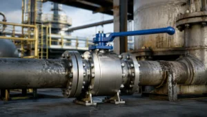
When Metal Seats Make Sense
Metal seats are normally considered when a polymer seat may be cut, softened, deformed, extruded, chemically attacked, or filled with deposits.
- Slurry containing sand, catalyst, ash, scale, minerals, or metal particles
- Hot gas, steam, thermal oil, or refinery process fluid
- Coking, polymerizing, crystallizing, or sticky media
- High-cycle automated isolation
- Large valves operating against high differential pressure
- Processes in which solids collect around the ball or seats
- Applications requiring a qualified fire-tested valve design
Metal seats are not the correct answer for every difficult application. Clean fluid may be sealed more tightly by PTFE, reinforced PTFE, PEEK, or another compatible soft-seat material. Continuous throttling may require a V-port, segmented ball, or purpose-built control valve. Cryogenic, oxygen, chlorine, hydrogen, and nuclear applications require separate reviews.
Fluid Data
A supplier cannot select the correct materials, coating, clearances, or actuator from a fluid name such as “slurry,” “steam,” or “dirty gas.”
For solids and slurry, provide:
- Normal and maximum solids concentration
- Typical particle-size range
- Maximum particle size
- Particle hardness and shape
- Particle density
- Fluid viscosity at operating temperature
- Normal and maximum flow rate
- Whether the solids settle, pack, stick, or form lumps
Large hard particles may chip a brittle coating or stop the valve from closing. Fine particles can enter seat pockets, springs, bearings, and stem clearances. Flat particles may bridge a narrow gap, while dense particles may collect at the bottom of the body after flow stops.
Do not report only an average particle size. For example, a process may contain mostly particles between 50 and 300 μm but occasionally carry 1 mm pieces of scale. The fine particles may fill the seat pocket, while the larger pieces may damage the coating.
For corrosive service, provide:
- Complete chemical composition
- Water and chloride content
- Acid, caustic, sulfur, or H2S concentration
- Gas and liquid phases
- Normal and upset temperature
- Possible condensation
- Cleaning and flushing chemicals
The review may need to cover general corrosion, pitting, crevice corrosion, stress corrosion cracking, galvanic attack, hydrogen-related cracking, and corrosion beneath a damaged coating.
For sticky or reactive media, explain:
- What causes the fluid to polymerize, coke, crystallize, or freeze
- How quickly deposits form
- Whether the deposits become hard or remain soft
- Whether air, moisture, cooling, or pressure loss starts the reaction
- How the line is cleaned before shutdown
The cleaning fluid may create a more severe condition than the normal process. Steam can raise temperature, solvent can damage secondary seals, and water can react with process residue.
Operating Conditions
Normal operation is only one part of the valve duty. Maximum pressure, maximum temperature, maximum differential pressure, and the highest solids concentration may occur at different times.
- Minimum, normal, maximum, and design temperature
- Short-term temperature peaks
- Heating and cooling rate
- Normal and maximum line pressure
- Maximum differential pressure while opening
- Maximum differential pressure while closing
- Vacuum and reverse-pressure conditions
- Pressure and temperature during cleaning
- Emergency shutdown conditions
- Time normally held open or closed
Line pressure is the pressure inside the valve. Differential pressure is the difference between the upstream and downstream sides. Differential pressure often has the greatest effect on seat load and actuator torque.
A valve may normally operate with only 5 bar differential pressure but be required to close against the full line pressure during an emergency. That emergency condition must be included in the actuator calculation.
The following table shows how one project may contain several different design cases.
| Illustrative Operating Case | Line Pressure | Temperature | Operating Differential Pressure | Valve Duty |
|---|---|---|---|---|
| Normal production | 65 bar | 180°C | 5 bar | Remains open |
| Normal isolation | 65 bar | 180°C | 65 bar | Closes |
| Steam cleaning | 8 bar | 300°C | 2 bar | Operates twice |
| Cold startup | 20 bar | 25°C | 20 bar | Opens after a 48-hour hold |
The values above are an illustrative example, not universal design limits. Replace them with the actual project conditions.
External conditions also matter. State the expected pipeline vibration, pipe load, thermal expansion, flange or weld-end misalignment, outdoor temperature, dust, salt, rain, ice, insulation, heat tracing, flooding, fire, and seismic requirements.
Floating or Trunnion
Floating ball: The ball is held mainly by the seats. Line pressure moves it slightly toward the downstream seat to create shutoff. This design is compact and often economical for smaller valves and moderate differential pressure.
As the sealing diameter and differential pressure increase, the ball is pushed harder against the downstream seat. This can raise contact stress, friction, wear, and operating torque.
Trunnion-mounted ball: The ball is mechanically supported at the top and bottom. The seats move toward the ball under spring and pressure loading. This structure is commonly used for larger sizes, higher differential pressure, automated isolation, and DBB or DIB arrangements.
Neither structure is automatically better. Selection should be based on seat load, torque, pressure direction, valve size, isolation function, and maintenance requirements. See CARILO’s floating and trunnion ball valve comparison for more detail.
Seat Pressure Effect
A trunnion valve may use single-piston-effect seats, double-piston-effect seats, or one of each.
Single-piston-effect seat: Line pressure normally pushes the seat toward the ball. If the cavity pressure rises above the pressure on one side by the amount required by the design, the seat can move away from the ball and release pressure.
Double-piston-effect seat: Pressure from either side can push the seat toward the ball. This can provide additional isolation, but the seats may not automatically relieve trapped cavity pressure. A separate relief device may be required.
DBB, DIB-1, and DIB-2 should not be ordered by name alone. The specification should state:
- Which side must remain isolated
- Normal and reverse pressure direction
- How the bleed point will be used
- How cavity pressure will be relieved
- How the isolation function will be tested
Bore Size
At the same flow rate, a smaller bore creates a smaller flow area, higher local velocity, and greater pressure loss. This can increase erosion when the fluid contains solids or liquid droplets.
| Reduction in Bore Diameter | Reduction in Flow Area | Increase in Velocity at the Same Flow Rate |
|---|---|---|
| 10% | 19.0% | 23.5% |
| 20% | 36.0% | 56.3% |
| 25% | 43.8% | 77.8% |
These values are calculated from the area of a circular bore. They show the geometric effect only. Actual pressure drop depends on the valve’s Cv or Kv, internal shape, fluid properties, and the complete piping system.
Full bore is often selected for piggable lines, high continuous flow, pump suction, and fluids containing deposits. However, a “full bore” label does not prove that a valve is piggable. Check the minimum internal opening, seat intrusion, ball alignment, weld penetration, and actual pig dimensions.
See CARILO’s full bore and reduced bore comparison for additional flow and pigging considerations.
Body Design
Two-piece body: Uses fewer main body joints and provides a compact structure. Internal access may be more limited than with a three-piece design.
Three-piece body: In many designs, the center body can be removed or swung out after the body bolts are released while the end pieces remain connected to the pipeline. The exact method depends on the valve construction and available space.
Top-entry body: Allows internal parts to be removed from above while the main body remains connected to the pipeline. The system must still be isolated, depressurized, drained, and confirmed safe.
Fully welded body: Removes large bolted body joints and reduces external leak paths. Internal repair is more difficult, so seat life, corrosion, coating quality, and spare-valve planning become more important.
For welded-end valves, the installation procedure must limit heat transferred to the packing, bearings, springs, secondary seals, and coated parts. The manufacturer should state the required ball position during welding and whether post-weld heat treatment is allowed.
ASME B16.34 applies to new valve construction within its scope and addresses pressure-temperature ratings, materials, dimensions, tolerances, nondestructive examination, testing, and marking.[1]
Seat and Cavity Design
A metal seat is a moving assembly, not just a metal ring. It may include:
- Seat ring and carrier
- Springs
- Graphite or another secondary seal
- Guide surfaces
- Pressure-balance areas
- Hardfacing or coating
- Contact band
- Debris space
- Cavity-relief path
Seat load can come from spring force, line pressure, cavity pressure, thermal expansion, assembly dimensions, and movement of a floating ball.
Too little load can cause leakage. Too much load increases friction, coating stress, wear, and actuator torque. The seat must remain effective at low pressure, maximum differential pressure, minimum temperature, maximum temperature, and after expected wear.
The contact band is the area where the seat touches the ball. A narrow band creates high local pressure and may cut through light deposits, but it may wear quickly. A wider band lowers local pressure but normally needs more force to seal.
Ball and seat pairs may be lapped together. The maintenance instructions should state whether the seats are interchangeable or whether the ball and seats must remain a matched set.
A closed ball valve can trap liquid in its body cavity. If the liquid becomes hotter, thermal expansion can raise cavity pressure quickly. Possible protection methods include self-relieving seats, an external thermal-relief connection, an internal relief path, or controlled venting.
A body drain is not automatically a thermal-relief device. It works as one only when it is correctly connected, pressure-rated, open when needed, and protected from blockage.
When API 6D is the governing specification and liquid trapping is possible, Addendum 3 to the 25th edition requires automatic cavity relief. For temperatures up to 250°F (121°C), the cavity-relief pressure must not exceed 33% above the applicable valve pressure rating.[2]
This API 6D requirement should not be copied into every industrial valve specification without checking the product standard, fluid state, temperature, valve rating, and project requirements.
Seat Pocket and Purging
Many severe-service valves leak because material enters the space behind the seat. Packed solids can stop seat movement, block springs, and hold the seat away from the ball even when the coating remains usable.
Possible controls include:
- Shielded seat pockets
- Protected springs
- Reduced dead space
- Scraper features
- Drainable cavities
- Purge or flush connections
A purge connection provides little value unless the plant defines the purge medium, pressure, flow rate, timing, discharge route, and contamination risk. A connection into the body cavity may not clean the area behind the seat.
Scraper edges also need control. A scraper may remove deposits, but a sharp or misaligned edge can damage the ball coating, especially when hard particles become trapped between the parts.
Coating and Material Selection
Do not select a coating from hardness alone. Start with the main form of damage:
- Abrasion: particles slide across the surface
- Erosion: particles or droplets strike the surface at speed
- Galling: metal transfers between sliding surfaces
- Impact: large particles chip or crack the surface
- Corrosion: fluid attacks pores, binder, or base material
- Thermal fatigue: repeated heating and cooling crack the surface
Tungsten carbide can provide strong resistance to fine-particle abrasion. The binder, corrosion environment, temperature, impact, and substrate stiffness must still be checked.
Chromium carbide is often considered for wear at higher temperature. Performance depends on the matrix, porosity, oxidation conditions, and application process.
Cobalt-based hardfacing can resist galling, heat, corrosion, and wear. Some plants restrict cobalt because of contamination or radiation-control requirements.
Nickel-based hardfacing can provide corrosion resistance and useful toughness. The exact alloy, hardness, thickness, and application process must be stated.
Similar or poorly matched metal surfaces can gall under high load, especially in dry gas or high-temperature service. A hardness difference alone does not prevent galling.
The base material must also support the coating. If the substrate bends, the coating may crack. If corrosion develops below a porous or damaged layer, the coating may separate.
For defined H2S-containing oil and gas production environments, ISO 15156-2 addresses cracking-resistant carbon and low-alloy steels, while ISO 15156-3 covers corrosion-resistant and other alloys.[3][4]
These standards do not replace a full corrosion review and do not automatically cover every refinery or chemical application.
For high-temperature material selection, see CARILO’s metal seated ball valve guide for 400°C service.
Coating Inspection
The coating specification should require measured results rather than a general coating name.
| Inspection Record | What Should Be Reported |
|---|---|
| Applied thickness | Measured thickness before final grinding |
| Finished thickness | Measured thickness after grinding and lapping |
| Hardness | Actual result, location, scale, and test method |
| Porosity | Measured percentage and inspection method |
| Bond strength | Test result and method, where required |
| Surface roughness | Final measured Ra value |
| Ball roundness | Maximum measured deviation |
| Seat contact | Contact pattern or approved inspection result |
Finished thickness should be checked after final machining. A coating that is thick enough after spraying may become too thin after grinding.
A witness coupon can show hardness, porosity, thickness, and bond quality on a sample. It cannot prove correct ball roundness, edge coverage, seat contact, hot leakage, or operating torque.
Repair rules should be agreed before production. Local grinding, recoating, or weld repair can change geometry, heat input, residual stress, and final thickness.
Small Parts
Springs, bearings, thrust washers, fasteners, packing, and secondary seals can set the real operating limit.
- A spring may lose preload after long high-temperature exposure.
- A bearing may wear quickly in dry gas or abrasive fluid.
- A secondary seal may set a lower temperature limit than the metal seat.
- A fastener may exceed a hardness limit for H2S service.
- A thrust washer may swell or soften in the process fluid.
- A small carbon-steel part may corrode inside an alloy valve.
The supplier should provide a complete bill of materials, not only the body, ball, seat, and stem materials.
High Temperature
The ball, seats, body, stem, springs, bearings, and packing do not heat at the same rate. Temporary temperature differences can change clearance, alignment, contact load, and torque.
- Expansion of the ball, seats, stem, and body
- Loss of material strength at temperature
- Spring stress relaxation
- Packing and bearing temperature
- Coating and substrate expansion difference
- Uneven heating from insulation or heat tracing
A valve may pass a room-temperature test but leak when hot. It may also seal when hot and become difficult to operate during cooldown.
High-temperature testing should measure temperature near the critical internal parts. A thermocouple on the outside of the body does not prove that the ball and seats have reached a stable temperature.
An illustrative thermal test may heat a prototype from ambient temperature to 300°C, hold it until the internal sensors are stable, operate it three times, complete the hot leakage test, cool it to ambient temperature, and then repeat the leakage and torque measurements. The actual temperature, hold period, cycle count, and pressure must come from the project test plan.
Cryogenic service requires a separate review of material toughness, contraction, bonnet extension, packing location, and trapped liquid. See CARILO’s cryogenic ball valve range for this separate service category.
Throttling and Operating Speed
A standard ball valve is normally used for isolation, not continuous flow control.
At partial opening, flow passes through a small crescent-shaped area. Local velocity increases, and solids or droplets can strike the ball edge and downstream seat.
- Seat-edge erosion
- Coating loss
- Noise and vibration
- Cavitation or flashing
- Unstable torque
- Rapid leakage increase
Slow movement is not always safer. If the valve remains longer in the most erosive partial-open position, a slow stroke can increase damage. Some applications need slow movement near final closure and faster movement through the middle of the stroke.
Define the normal opening time, normal closing time, emergency stroke time, speed near the seats, end-of-stroke cushioning, and minimum actuator supply pressure.
A pneumatic spring-return actuator may move at a different speed during failure than during normal powered operation. Hydraulic accumulators can also create a different speed profile from the normal pump supply.
Torque and Actuator
Actuator sizing should use a documented torque calculation rather than one value from a general size chart.
- Break-to-open torque
- Running torque
- End-to-close torque
- Seating torque
- Maximum service torque
- Maximum allowable stem torque
Torque should be checked at the worst credible combination of differential pressure, temperature, packing load, deposits, seat load, and actuator supply pressure.
Additional margin may be needed for long static periods, solids buildup, corrosion, packing aging, cold startup, and manufacturing tolerance. The supplier should state the margin rather than hide it inside the actuator selection.
More actuator torque is not always safer. Excess output can twist the stem, break the drive key, damage the seats, overload the bracket, or force the valve against its stop.
MAST means maximum allowable stem torque. Maximum actuator output, including high supply pressure or electric-motor stall, should not exceed the safe capacity of the stem and drive parts.
For API 6D pipeline valves, API 6DX covers the mechanical integrity and sizing of electric, pneumatic, and hydraulic actuators and their mounting kits.[5]
The following example uses a torque index rather than one N·m value, because actual torque changes greatly with valve size, pressure, seat design, and actuator conditions.
| Illustrative Test Stage | Breakaway Torque Index | Running Torque Index | Leakage Result |
|---|---|---|---|
| Before testing | 100 | 100 | Within agreed limit |
| After thermal cycling | 108 | 104 | Within agreed limit |
| After mechanical cycling | 116 | 109 | Within agreed limit |
| After solids exposure | 124 | 115 | Compare with project limit |
The starting value is shown as an index of 100. This table is an example of trend reporting, not a universal acceptance limit.
Leakage, Emissions, and Fire Testing
“Zero leakage” is incomplete unless the test conditions are stated.
- Test standard
- Test medium
- Test pressure
- Pressure direction
- Valve temperature
- Hold time
- Permitted leakage
- Whether the test is before or after cycling
ISO 5208 covers examinations and tests used to verify the pressure boundary, closure tightness, and structural condition of metallic valves. The applicable product standard may add or change requirements.[6]
Shell test: Checks the pressure-containing body and joints.
Seat test: Checks leakage through the closed valve.
Low-pressure gas test: Can reveal small leakage paths that may not be visible during a liquid test.
Passing a shell test does not prove seat tightness. Passing a high-pressure water seat test does not automatically prove low-pressure gas tightness.
ISO 15848-1 covers classification and type testing of valve stem or shaft seals and body joints for fugitive emissions. ISO 15848-2 covers production acceptance testing.[7][8]
A type-tested design does not mean that every production valve receives the full type test. Check the qualified size, stem diameter, packing arrangement, pressure class, temperature range, cycle count, and permitted design changes.
A metal seated valve is not automatically fire-safe. Packing, gaskets, bearings, secondary seals, and body joints can still change during fire exposure.
API 598 covers valve inspection and pressure testing within its scope. API 607 covers fire testing of quarter-turn valves with metallic or nonmetallic seats and certain other operated valves. API 641 covers fugitive-emission type testing of quarter-turn valves.[9]
If the valve must move during a fire, the actuator, air tubing, solenoid valve, cable, hydraulic hose, switches, and control system may require separate protection.
For more test-planning details, see CARILO’s API 6D ball valve testing guide.
Standards
The purchase order should state the exact standard, edition, addenda, and project requirements.
- ASME B16.34: Pressure-temperature ratings and general construction requirements within its scope
- API 608: Specified metal ball valves with flanged, threaded, and welding ends
- API 6D: Pipeline and piping valves within its stated scope
- API 598 or ISO 5208: Inspection and pressure testing when specified
- API 607 or API 6FA: Fire testing, depending on the valve type and project
- API 641 or ISO 15848: Fugitive-emission testing
- ISO 15156 / NACE MR0175: Defined H2S-containing oil and gas production environments
API states that the 7th edition of API 608, Metal Ball Valves—Flanged, Threaded and Welding Ends, became effective on October 2, 2025.[10]
“Designed to,” “tested to,” “type tested,” “certified,” and “API Monogram marked” do not mean the same thing. Ask the supplier to identify the exact evidence supporting each statement.
Rapid Prototyping
Rapid prototyping should shorten the learning process, not remove safety checks.
| Prototype Type | What It Can Check | What It Cannot Prove |
|---|---|---|
| Appearance prototype | Size, connections, actuator space, maintenance access | Pressure, leakage, torque, temperature, or life |
| Functional prototype | Assembly, movement, seat travel, actuator connection | Full severe-service performance if materials are not representative |
| Production-intent prototype | Pressure, leakage, torque, heat, cycles, and wear | Every possible field condition |
| Qualification prototype | Agreed qualification tests and failure criteria | Automatic approval for field use after destructive testing |
A useful severe-service prototype should use the intended ball and seat materials, coating process, finished thickness, springs, bearings, packing, secondary seals, lapping method, and assembly procedure.
Digital design, fixtures, non-pressure mock-ups, and changes to an existing valve platform may be accelerated. Pressure-boundary materials, heat treatment, welding, coating, nondestructive examination, and required pressure tests should not be skipped.
Prototype Test Plan
Agree on the acceptance criteria before the prototype is manufactured.
- Confirm materials, dimensions, coating, and assembly records.
- Measure initial shell and seat leakage.
- Record torque through the full stroke.
- Perform the required thermal, pressure, cycle, or solids exposure.
- Repeat leakage and torque checks at planned intervals.
- Complete the final pressure and functional tests.
- Disassemble and inspect the valve.
- Correct the design and repeat affected tests when needed.
For an illustrative 1,000-cycle prototype test, torque and leakage may be checked at cycles 0, 250, 500, 750, and 1,000. The actual cycle count and inspection intervals must be agreed before testing.
| Illustrative Checkpoint | Required Records |
|---|---|
| Cycle 0 | Initial leakage, breakaway torque, running torque, and position |
| Cycle 250 | Leakage and torque trend |
| Cycle 500 | Leakage, torque, packing condition, and actuator travel |
| Cycle 750 | Leakage and torque trend |
| Cycle 1,000 | Final leakage, torque, full function, and strip inspection |
Possible failure criteria include:
- Leakage above the agreed limit
- Torque above the actuator or stem limit
- Failure to complete the full stroke
- Coating cracking, chipping, or separation
- Seat or spring jamming
- Stem or body-joint leakage
- Permanent deformation
- Failure of the cavity-relief function
After testing, inspect the contact band, scratch direction, coating loss, cracks, edge damage, springs, bearings, packing, deposits, and dimensional change.
A laboratory cycle count does not automatically equal a fixed number of field years. Prototype testing reduces uncertainty but cannot reproduce every plant condition.
Production Control
A successful prototype must be transferred into controlled production documents.
- Approved drawings and bill of materials
- Material and heat-treatment records
- Welding and hardfacing procedures
- Coating parameters and inspection limits
- Grinding and lapping procedures
- Critical dimensional records
- Assembly instructions
- Torque and pressure-test procedures
- Repair and nonconformance rules
- Final document requirements
Changing the coating supplier, ball material, seat material, spring, bearing, packing, heat treatment, critical clearance, or lapping process should require engineering review.
A different coating supplier is not automatically equivalent. Equipment, powder, process settings, grinding, and inspection can change the finished result.
Installation and Maintenance
A correctly designed valve can be damaged during installation. Keep welding slag, sand, scale, tools, and other debris away from the sealing surfaces.
Before commissioning, confirm:
- Correct flow direction and orientation
- Correct actuator stops and position indication
- Connected purge, drain, and relief lines
- Minimum actuator supply pressure
- Manual override operation
- No pipe strain or external interference
- Baseline torque or actuator-pressure reading
Do not use the valve to pull misaligned piping together. Do not lift the valve by its actuator, tubing, or handwheel unless the manufacturer has approved the method.
Maintenance instructions should state whether the ball and seats must be replaced as a matched set, which coatings can be repaired, and which work must return to the factory.
Track torque or actuator pressure over time. A gradual increase may indicate deposits, packing friction, bearing wear, corrosion, or seat damage. A sudden decrease may indicate a broken drive part or loss of seat loading.
CARILO’s industrial valve service page lists available engineering support, spare parts, material verification, NDE, testing, and documentation services.
Supplier Review
Ask the supplier to support its proposal with:
- References from technically similar service
- Material-selection basis
- Seat and cavity-relief explanation
- Coating procedure and inspection method
- Torque calculation and actuator curve
- Prototype test procedure
- Production inspection plan
- Material traceability example
- Repair and nonconformance procedure
- Sample final data book
A reference from the same industry is not enough. Compare the actual fluid, solids, pressure, temperature, valve size, differential pressure, cycle rate, leakage limit, and operating time.
Ask which coating, heat-treatment, inspection, and testing work is completed in-house and which is outsourced. Also ask what design changes require repeat qualification.
RFQ Checklist
Valve information:
- Size, quantity, pressure class, and end connection
- Pipe schedule and minimum clear bore
- Full or reduced bore
- Body style and installation position
- Flow and sealing direction
- Pigging and maintenance-space requirements
Process information:
- Complete fluid composition
- Solids concentration, size, shape, and hardness
- Viscosity and vapor pressure
- Normal and maximum flow
- Operating and design pressure
- Maximum differential pressure during movement
- Minimum, normal, maximum, and transient temperature
- Startup, shutdown, cleaning, and upset conditions
Operating information:
- Isolation, switching, emergency, or throttling duty
- Normal and total expected cycles
- Time held in one position
- Opening and closing time
- Fail position
- Reverse-pressure requirement
Performance information:
- Leakage limit and complete test conditions
- Fire-test requirement
- Fugitive-emission requirement
- Cavity-relief method
- DBB or DIB function
- Maximum torque and cycle-life target
Quality information:
- Applicable standards, editions, and addenda
- Material certificates and PMI
- Nondestructive examination
- Coating records
- Prototype and production tests
- Customer and third-party witness points
- Final documentation
The following example shows how the main data can be written in one RFQ line:
NPS 6, Class 600, full bore, trunnion mounted, 65 bar normal line pressure, 65 bar maximum operating differential pressure, 180°C normal temperature, 300°C steam-cleaning temperature, 3% solids by weight, 50–300 μm normal particle size, 1 mm occasional maximum particle size, 20 operations per month, fail-close pneumatic actuator.
This is an illustrative RFQ example only. Replace every value with the actual project data.
If a parameter is unknown, mark it as unknown rather than entering an unverified estimate. Ask the supplier to state the resulting assumption, risk, design margin, or added test requirement.
Request Engineering Review
A useful engineering response should include:
- A list of missing process data
- The proposed valve structure
- Ball, seat, coating, and small-part materials
- Seat-pocket and cavity-relief design
- Pressure-temperature basis
- Leakage acceptance criteria
- Torque and actuator-sizing basis
- Applicable standards and deviations
- Prototype level and manufacturing plan
- Inspection and test plan
- Production-release requirements
The review may conclude that a standard valve is suitable, an existing design needs limited changes, a full prototype is required, or a ball valve is not the correct valve type.
Send the process datasheet, existing valve information, failure photographs, project specifications, quantity, and required delivery date through CARILO’s engineering review and quotation page.
Conclusion
A reliable custom metal seated ball valve starts with measurable data, not a general “severe service” label. Provide the particle range, maximum operating differential pressure, real pressure-temperature combinations, stroke time, cycle count, and exact leakage test. A production-intent prototype should use the final ball, seats, coating, springs, bearings, packing, and lapping process. Record leakage and torque at cycle 0 and at agreed test intervals, then inspect the contact band, coating, springs, and bearings. Release production only after all failures are corrected and the approved materials, clearances, coating process, actuator sizing, inspection points, and repair limits are frozen.







