
Full bore ball valves are usually better for piggable pipelines, high continuous flow, pump suction lines, and fluids containing solids or deposits. Reduced bore valves can reduce purchase cost and weight, but they create a smaller flow area, higher local velocity, and greater pressure loss.
A reduced bore valve is suitable when the line is clean, flow is low or intermittent, pigging is not required, and the calculated pressure loss remains within the system limit. The final choice should be based on the actual bore, Cv or Kv, pipe dimensions, flow rate, fluid properties, torque, and total lifecycle cost.
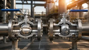
Quick Comparison
| Item | Full Bore | Reduced Bore |
|---|---|---|
| Internal opening | Close to the required pipe bore | Smaller than the pipe bore |
| Flow capacity | Higher | Lower |
| Pressure drop | Lower | Higher |
| Local velocity | Lower | Higher |
| Conventional pigging | Usually suitable after passage checks | Usually unsuitable unless specially engineered |
| Solids and deposits | Better passage | Higher blockage and wear risk |
| Valve weight | Usually higher | Usually lower |
| Operating torque | Often higher | Often lower |
| Initial cost | Usually higher | Usually lower |
| Energy cost | Usually lower | Can be higher |
These are general differences. Two valves with the same nominal size can have different bore dimensions, flow coefficients, seat designs, body lengths, weights, and torque values.
Bore Size
NPS and DN are nominal connection sizes. They do not show the exact inside diameter of a pipe or valve. Pipe inside diameter changes with wall thickness and schedule, so an NPS 8 pipe does not always have an 8-inch inside diameter.[1]
The minimum valve passage may be limited by:
- The opening through the ball
- The seat-ring opening
- The valve body passage
- The flange or weld-end bore
- Internal coating or lining
- Weld metal projecting into the pipe
- Misalignment between the ball, body, and connecting pipe
The smallest opening controls pig clearance. The complete internal shape affects pressure loss.
The terms full bore, full port, and full opening are often used for the same basic design. Reduced bore, reduced port, and standard port usually describe a smaller opening. Because manufacturers may use these terms differently, check the minimum bore shown on the certified drawing.
Bore type is not the same as pressure class. A reduced bore valve can have the same pressure class as a full bore valve. Pressure class tells you the valve’s pressure-temperature rating. Bore type tells you the size of the flow passage.
For more detail, see this guide to full bore ball valves and pigging requirements.
Flow Area
Flow area depends on the square of the bore diameter:
A = πD² / 4
This means a small decrease in diameter produces a much larger decrease in flow area.
| Bore Diameter Reduction | Remaining Flow Area | Flow Area Lost |
|---|---|---|
| 10% | 81.0% | 19.0% |
| 15% | 72.3% | 27.8% |
| 20% | 64.0% | 36.0% |
| 25% | 56.3% | 43.8% |
| 30% | 49.0% | 51.0% |
For example, reducing an opening from 8 inches to 6 inches reduces the diameter by 25%, but it removes about 44% of the flow area.
| Opening | Flow Area | Area Compared with 8 Inches |
|---|---|---|
| 8 inches | 50.3 in² | 100% |
| 6 inches | 28.3 in² | 56.3% |
The area ratio does not directly equal the pressure-loss ratio. Pressure drop also depends on the seat opening, passage length, inlet shape, downstream expansion, internal surface, and pressure recovery. Use the exact valve Cv or Kv for pressure-drop calculations.
Flow Velocity
When the same flow passes through a smaller area, local velocity increases:
V = Q / A
The table below shows how bore reduction affects velocity when the flow rate stays the same.
| Bore Diameter Reduction | Remaining Flow Area | Local Velocity Increase |
|---|---|---|
| 10% | 81.0% | 23% |
| 15% | 72.3% | 38% |
| 20% | 64.0% | 56% |
| 25% | 56.3% | 78% |
| 30% | 49.0% | 104% |
A 30% reduction in bore diameter leaves only 49% of the original flow area. Local velocity therefore becomes slightly more than twice the original value.
Assume a water flow of 3,000 US gallons per minute, or about 6.68 ft³/s.
| Opening | Area | Local Velocity |
|---|---|---|
| 8 inches | 0.349 ft² | 19.1 ft/s |
| 6 inches | 0.196 ft² | 34.0 ft/s |
The 6-inch opening raises local velocity by about 78%.
These values are calculation examples, not recommended operating limits. Acceptable velocity depends on the fluid, pipe material, vapor pressure, solids content, noise limit, and erosion risk.
The higher velocity exists inside the smaller valve passage. The velocity in the larger upstream and downstream pipe remains based on the pipe’s own inside diameter.
Higher local velocity can increase:
- Erosion from sand, scale, rust, or catalyst particles
- Noise and vibration
- Seat and coating wear
- Downstream turbulence
- Cavitation risk in liquid service
Pressure Drop
Cv and Kv are the main values used to compare the flow capacity of actual valve models.
Cv is commonly used with US customary units. For a water-like liquid under suitable conditions:
ΔP = SG × (Q / Cv)²
- ΔP = pressure drop in psi
- SG = liquid specific gravity relative to water
- Q = flow in US gallons per minute
- Cv = valve flow coefficient
Kv is the metric flow coefficient. K is a dimensionless resistance value often used in complete pipe-network calculations.
Valve sizing standards use different equations and correction factors for liquids, gases, viscosity, attached fittings, choking, and pressure recovery.[2]
Use the Cv or Kv for the exact valve size, pressure class, bore, seat design, end connection, flow direction, and opening position.
The table below shows how a lower Cv affects pressure drop when flow and liquid specific gravity stay unchanged.
| Valve Cv Compared with the Reference Valve | Pressure-Drop Multiplier |
|---|---|
| 90% | 1.23× |
| 80% | 1.56× |
| 70% | 2.04× |
| 60% | 2.78× |
| 50% | 4.00× |
| 40% | 6.25× |
| 25% | 16.00× |
If one valve has half the Cv of another valve, it creates four times the pressure drop at the same liquid flow. If its Cv is one-quarter of the reference value, it creates 16 times the pressure drop.
This mathematical relationship does not mean every reduced bore valve has the same Cv reduction. Use certified data for the offered model.
For more examples, see this guide to ball valve pressure-drop calculations.
Pressure-Drop Example
Assume a manufacturer offers two NPS 8 valves with the following full-open Cv values:
- Full bore Cv: 10,000
- Reduced bore Cv: 2,500
For water at 3,000 gpm:
| Valve | Calculation | Pressure Drop |
|---|---|---|
| Full bore | (3,000 / 10,000)² | 0.09 psi |
| Reduced bore | (3,000 / 2,500)² | 1.44 psi |
The reduced bore valve adds:
1.44 – 0.09 = 1.35 psi
Its pressure drop is 16 times the full bore value in this example. However, the more useful figure is the absolute difference of 1.35 psi because this can be compared with the pressure available in the system.
A 1.35 psi loss may be acceptable in a line with ample pressure. It may be important in a pump suction line, gravity system, compressor suction line, or pipe network with several valves.
Pressure drop rises approximately with the square of flow when the valve Cv and liquid properties remain unchanged.
| Flow Increase | New Pressure Drop | Pressure-Drop Increase |
|---|---|---|
| 10% | 1.21× | 21% |
| 20% | 1.44× | 44% |
| 25% | 1.56× | 56% |
| 50% | 2.25× | 125% |
| 75% | 3.06× | 206% |
| 100% | 4.00× | 300% |
A 50% flow increase makes pressure drop 2.25 times higher. Doubling flow makes pressure drop four times higher.
For the reduced bore valve with Cv 2,500:
| Flow | Calculated Pressure Drop |
|---|---|
| 1,000 gpm | 0.16 psi |
| 2,000 gpm | 0.64 psi |
| 3,000 gpm | 1.44 psi |
| 4,000 gpm | 2.56 psi |
| 5,000 gpm | 4.00 psi |
Check normal, maximum, emergency, and future flow before selecting the valve bore.
Energy Cost
A pump must provide the pressure lost across the valve when the system is required to maintain the same flow. Unnecessary pressure loss can therefore increase energy use.[3]
For a water-like liquid:
Hydraulic hp = Q × ΔP / 1714
Using the extra 1.35 psi from the previous example:
Hydraulic hp = 3,000 × 1.35 / 1714 = 2.36 hp
Assume the combined pump, motor, and drive efficiency is 70%:
Input power = approximately 2.52 kW
The table below shows how annual operating hours affect energy cost at $0.12/kWh.
| Annual Operating Hours | Added Energy | Added Electricity Cost |
|---|---|---|
| 1,000 hours | 2,520 kWh | $302 |
| 2,000 hours | 5,040 kWh | $605 |
| 4,000 hours | 10,080 kWh | $1,210 |
| 6,000 hours | 15,120 kWh | $1,814 |
| 8,000 hours | 20,160 kWh | $2,419 |
A valve used only 1,000 hours per year creates a much smaller energy penalty than the same valve operating continuously.
Electricity price also changes the result. Using approximately 20,100 kWh per year:
| Electricity Price | Annual Added Cost |
|---|---|
| $0.08/kWh | $1,608 |
| $0.10/kWh | $2,010 |
| $0.12/kWh | $2,412 |
| $0.15/kWh | $3,015 |
| $0.20/kWh | $4,020 |
For six valves with the same additional 1.35 psi loss:
- Total additional pressure drop: 8.1 psi
- Additional input power: approximately 15.1 kW
- Annual cost at 8,000 hours and $0.12/kWh: approximately $14,500
The real result depends on the pump and control method:
- A fixed-speed pump may produce less flow when system resistance rises.
- A variable-speed pump may increase speed to hold the required flow.
- A pressure-control system responds according to the pressure-measurement location.
A proper energy review should use the pump curve, system curve, load profile, and efficiency at the actual operating point. The US Department of Energy recommends checking the complete pumping system rather than evaluating the pump alone.[4]
If a full bore valve costs $8,000 more, its simple payback depends on the annual saving:
| Annual Saving | Simple Payback |
|---|---|
| $1,000 | 8.0 years |
| $2,000 | 4.0 years |
| $2,420 | 3.3 years |
| $4,000 | 2.0 years |
| $8,000 | 1.0 year |
Simple payback does not include discount rate, changing energy prices, maintenance, or future flow increases.
Liquid Limits
The basic Cv equation is suitable for an early comparison of water-like, single-phase liquids. It may need correction for:
- High-viscosity oil
- Entrained gas
- Two-phase flow
- Flashing
- Cavitation
- Attached reducers or fittings
Permanent pressure loss and the lowest pressure inside the valve are not the same.
Permanent pressure loss affects pump duty and energy use.
Local minimum pressure affects cavitation and flashing.
If pressure inside the valve falls below the liquid vapor pressure, vapor forms. If the bubbles later collapse, the condition is cavitation. If the vapor remains downstream, the condition is flashing.
A small inlet-to-outlet pressure drop does not prove that cavitation cannot occur. Severe liquid service requires the manufacturer’s pressure-recovery data and a suitable sizing method.
Pressure loss is especially important at a pump suction because it reduces the available net positive suction head, or NPSH. Too little NPSH margin can cause noise, vibration, reduced pump performance, and impeller damage.
Gas Service
Do not use the simple liquid equation for natural gas, hydrogen, air, or steam.
Gas calculations require:
- Absolute upstream and downstream pressure
- Temperature
- Gas specific gravity or molecular weight
- Compressibility factor
- Specific-heat ratio
- Valve Cv
- Valve pressure-ratio factor
- Attached fitting corrections
A reduced bore valve may lower downstream pressure and increase local velocity, aerodynamic noise, vibration, and dynamic loading.
Gas flow can also become choked. After the valve reaches its choked-flow limit, lowering downstream pressure further does not increase flow in the same proportion. The limit depends on the exact valve design and gas properties, not on one universal pressure ratio.
Pigging
Pipeline pigs are used to clean the line, remove liquid, separate products, check internal clearance, or inspect the pipe.
PHMSA describes cleaning pigs, gauging pigs, and instrumented inspection tools. Instrumented tools can identify problems such as corrosion, cracks, dents, gouges, and buckles.[5]
| Tool | Main Use | Risk at a Restriction |
|---|---|---|
| Foam pig | Light cleaning and drying | Tearing, bypass, or loss of movement |
| Cup or disc pig | Cleaning, batching, and liquid removal | Cup damage or sticking |
| Gauge pig | Check minimum pipeline clearance | Bent plate or pig stoppage |
| Caliper tool | Measure internal geometry | Mechanical-arm damage |
| MFL tool | Detect metal loss | Magnet, sensor, or body damage |
| Ultrasonic tool | Measure wall thickness or cracks | Sensor damage or poor measurement |
A conventional pigging or in-line inspection route should normally have a verified full-opening passage unless the tool supplier has approved every known diameter reduction.
US gas pipeline rules generally require covered new transmission lines and replaced line pipe, valves, fittings, or other components to accommodate instrumented internal inspection devices, subject to listed exceptions.[6]
US hazardous-liquid pipeline rules contain a similar requirement for covered new pipelines and replaced main-line components, also with stated exceptions.[7]
A full bore valve alone does not make the whole pipeline piggable. Check:
- Minimum valve bore
- Seat and ball alignment
- Weld penetration
- Internal steps
- Bend radius
- Tees and branches
- Reducers
- Check valves
- Dents and deposits
The valve must also reach its true fully open position. A wrongly adjusted actuator stop can leave the ball partly closed even when the external indicator shows “open.”
Specify the minimum clear bore, maximum internal step, bore alignment tolerance, pig dimensions, valve orientation, and full-open stop setting.
Dirty Service
A reduced bore valve creates higher local velocity and a smaller passage. This can increase wear and blockage when the fluid contains solids or deposits.
| Material in the Fluid | Main Risk | Possible Result |
|---|---|---|
| Sand, rust, or scale | High-speed impact | Ball, seat, and body wear |
| Wax or sludge | Deposit buildup | Higher torque and smaller effective bore |
| Fibers | Bridging or wrapping | Partial or complete blockage |
| Crystals | Growth around the seat | Failure to fully open or close |
| Polymerizing fluid | Reaction in trapped fluid | Valve seizure or contamination |
Full bore is commonly preferred for waxy crude oil, produced water containing sand, slurry, pulp, catalyst fines, scaling liquid, and wastewater containing fibers.
Full bore does not remove every wear problem. Severe service may also require:
- Metal seats
- Hard-coated balls and seats
- Erosion-resistant trim
- Cavity flushing
- Drain or vent connections
- A pocketless or reduced-cavity design
See this guide to protecting ball valves from sand and abrasive media.
Bore type and seat type are separate choices. This soft-seated vs metal-seated valve comparison explains when each seat construction is suitable.
Weight and Torque
A reduced bore valve can use a smaller ball, seat, stem, body cavity, and actuator. This often reduces weight and cost.
However, weight differences cannot always be attributed to bore size alone. One valve may also use a shorter face-to-face pattern or a different body design.
When comparing valve weight, confirm that both quotations use:
- The same pressure class
- The same face-to-face length
- The same body material
- The same valve construction
- The same gearbox or actuator scope
Operating torque is affected by more than ball diameter:
- Differential pressure
- Seat material and preload
- Floating or trunnion-mounted construction
- Stem packing
- Temperature
- Deposits and contamination
- Time left in one position
- Required operating speed
A floating ball valve uses line pressure to push the ball against the downstream seat. A trunnion-mounted ball valve supports the ball with bearings and normally suits larger sizes and higher differential pressures.
Request:
- Breakaway torque
- Running torque
- Closing torque
- Maximum service torque
- Maximum allowable stem torque
- Actuator safety factor
- Minimum actuator supply pressure
This guide to reading a valve torque curve explains the main torque values used for actuator selection.
Cost Analysis
The lowest valve price does not always produce the lowest total cost.
Total cost = Purchase + Installation + Energy + Maintenance + Risk
| Cost Group | Items to Include |
|---|---|
| Purchase | Valve, gearbox, actuator, mounting kit, and controls |
| Installation | Freight, lifting, supports, labor, welding, inspection, and commissioning |
| Energy | Pumping or compression power caused by pressure loss |
| Maintenance | Seats, seals, actuator service, draining, and flushing |
| Risk | Stuck pigs, inspection-tool damage, shutdown, excavation, and lost production |
A reduced bore valve may have the lowest total cost when:
- The line is not piggable
- Flow is low or intermittent
- The fluid is clean
- Pressure margin is large
- Weight and installation space are important
A full bore valve may have the lowest total cost when:
- The line operates continuously at high flow
- Several valves are installed in series
- Pigging or in-line inspection is required
- The fluid contains solids or deposits
- Future flow may increase
- Downtime is expensive
Control Service
A standard isolation ball valve should not be used for continuous throttling unless the manufacturer approves that service.
Partial opening can create high jet velocity, seat-edge wear, cavitation, noise, vibration, and unstable torque. Continuous flow control normally requires a purpose-designed V-port, characterized, or segmented-ball control valve.
Standards
API Specification 6D covers the design, manufacturing, testing, marking, and documentation of pipeline valves. API 6D, 25th edition, was issued in November 2021. Addendum 3 was issued on March 5, 2025, with an API Monogram Program effective date of September 5, 2025.[8]
See this API 6D forged ball valve overview for available full bore and reduced bore configurations.
ISO 14313:2025 covers pipeline valve design, manufacturing, materials, welding, quality control, testing, and documentation for ASME Classes 150, 300, 600, 900, 1500, and 2500. It supplements API 6D, 25th edition.[9]
ASME B16.34 covers pressure-temperature ratings, materials, dimensions, tolerances, nondestructive examination, testing, and marking for applicable valves.[10]
Compliance with a valve standard does not automatically confirm acceptable pressure drop, pig passage, velocity, torque, or suitability for dirty service. These requirements must be stated separately in the purchase specification.
Procurement Checks
| Check | Required Evidence | Warning Sign |
|---|---|---|
| Minimum bore | Certified drawing with dimensions and tolerances | “Full port” is stated without a bore dimension |
| Flow capacity | Cv or Kv for the exact offered valve | A generic value is copied from another model |
| Pressure drop | Calculation at normal, maximum, and future flow | Only “low pressure drop” is stated |
| Pig passage | Written check against the actual pig dimensions | The valve is called piggable without tool data |
| Torque | Breakaway, running, closing, and maximum torque | Only one unexplained torque value is supplied |
| Actuator | Sizing at minimum supply with a stated safety factor | The actuator model is listed without a calculation |
| Weight | Complete valve, gearbox, actuator, and controls | Only bare-valve weight is shown |
| End bore | Drawing matched to the pipe schedule | The weld-end opening does not match the pipe |
| Testing | Defined shell, seat, functional, fire, and emissions tests | Required tests or reports are excluded |
Before ordering, provide the supplier with:
- Pipe size, schedule, and inside diameter
- Pressure class
- Required minimum clear bore
- Fluid composition, density, viscosity, and vapor pressure
- Minimum, normal, maximum, and future flow
- Operating and design pressure
- Operating and design temperature
- Solids type, size, and concentration
- Pig or inspection-tool dimensions
- Minimum Cv or Kv
- Maximum permitted pressure drop
- Seat and sealing requirements
- Actuator supply and operating time
- Applicable standards and editions
Conclusion
Full bore is normally the better choice for piggable lines, high continuous flow, pump suction, and fluids containing solids or deposits. Reduced bore is suitable when the line is clean, non-piggable, and the calculated loss is acceptable. A 25% reduction in bore diameter removes about 44% of the flow area and raises local velocity by about 78%. In the worked example, reducing Cv from 10,000 to 2,500 increased pressure drop from 0.09 to 1.44 psi at 3,000 gpm. Before ordering, verify the clear bore, Cv or Kv, maximum torque, complete valve weight, pig dimensions, and lifecycle cost.
Engineering note: The calculations in this article are examples. Final valve sizing, actuator selection, pigging review, and pressure-system design should be checked by qualified engineering personnel using certified supplier data and the project’s actual operating conditions.







