
| What You Notice | Check First |
|---|---|
| Hard before installation | Seat friction, stem packing, lock, stop, storage condition |
| Hard only when movement starts | Breakaway torque |
| Hard only under pressure | Differential pressure and seat load |
| Easy before installation, hard afterward | Pipe alignment, connection load, body stress |
| Hard at the same position every time | Debris, seat damage, stop or mechanical interference |
| Hard after actuator installation | Coupling alignment, actuator output, mounting bracket |
| Hard after several days of service | Deposits, contamination, fluid condition, temperature |
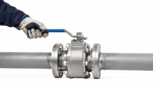
Hard Before Installation
If the valve is already firm before it goes into the pipe, pipe stress and system pressure are not the first things to blame. The resistance is coming from the valve itself.
On a soft-seated ball valve, the seats press against the ball so the closed valve can seal. That contact naturally creates friction, even before the valve sees line pressure. The seat load needs to be high enough to seal, but not so high that friction and wear become excessive.[1]
A firm new valve is usually less concerning when:
- the movement is smooth;
- there is no scraping or gritty feel;
- the valve reaches both intended stops;
- resistance is similar on repeated normal cycles.
Before looking for an internal fault, check the obvious items. A locking tab, detent pin or transport restraint may still be engaged. The handle may also be catching on nearby hardware.
Do not expect every new valve to become much easier after several cycles. Operating torque can rise or fall over time because of wear, contamination, deposits, packing condition and long periods without operation.
Hard Only When Movement Starts
Some valves need the most effort right at the start. The handle feels heavy for the first few degrees, then the movement becomes smoother. That usually points toward breakaway torque.
Breakaway torque is the torque needed to get a stationary ball moving. At that moment, the valve has to overcome static friction at the seats, stem packing and thrust surfaces. Once the ball is already moving, the torque may be lower.
For example, if one specific valve needs 30 N·m to start moving but 20 N·m during mid-stroke travel, its starting torque is 50% higher than its running torque. These figures are only a calculation example, not normal values for all ball valves.
This matters when an actuator is selected. The actuator has to cover the highest torque the valve needs, not just the easier part of the stroke. The ball valve torque curve guide explains break torque, running torque and sizing margin in more detail.
Hard Only Under Pressure
A valve that turns normally with no pressure but becomes much harder once the line is pressurized is giving you a useful clue: look at the differential pressure across the valve.
This matters especially on a floating ball valve. With the valve closed, pressure can move the ball slightly toward the downstream seat. The seat then presses harder against the ball, so more friction has to be overcome when the valve opens.
Line pressure and differential pressure are not the same thing.
Example 1:
- upstream: 150 psi;
- downstream: 0 psi;
- differential pressure: 150 psi.
150 psi is approximately 10.3 bar or 1.03 MPa.
Example 2:
- upstream: 150 psi;
- downstream: 140 psi;
- differential pressure: 10 psi.
10 psi is approximately 0.69 bar or 69 kPa.
The upstream pressure is the same in both examples, but the pressure difference across the closed valve is very different. These values only show the calculation and are not pressure ratings for a particular valve.
Floating and trunnion-mounted valves also carry pressure loads differently. The site’s floating vs. trunnion ball valve comparison explains the structural difference.
Never loosen, vent or partly dismantle a pressurized valve just to see whether the handle becomes easier.
Hard After Installation
If the valve was fine in your hand but becomes noticeably tighter after the piping is connected, start with the installation.
The body does not have to look visibly bent. A relatively small external load can shift the alignment of the body, stem, ball and seats enough to increase operating torque.
Check for:
- flanges that do not naturally line up;
- pipe being pulled into position through the valve;
- unsupported pipe hanging from the valve;
- a heavy actuator loading the stem sideways;
- excessive tightening of connections;
- thermal pipe movement after startup.
A valve should sit between correctly aligned pipes. It should not be used as the part that forces the piping into position.
The change in torque can be more useful than the final number itself. If the same valve requires 20 N·m before installation and 35 N·m immediately afterward under similar test conditions, torque has increased by 75%. That does not prove that 35 N·m is unsafe, but the increase is a strong reason to check alignment and installation load.
The ball valve installation and post-installation testing guide covers useful checks before and after the valve enters the piping system.
ASME B16.34 covers pressure-temperature ratings, materials, dimensions, testing and other requirements for many industrial metallic valves.[2]
Hard After Threaded or Union Connections Are Tightened
Threaded valves and plastic true-union valves can both become harder to turn after installation, but the way the load gets into the valve is different.
With a threaded valve, excessive tightening or poor wrench placement can send twisting force through the body. Use the wrenching points and tightening method specified for that valve rather than holding the far end of the body and applying large torque through the whole valve.
For PVC, CPVC and PP true-union valves, check:
- whether the pipe ends naturally line up;
- whether the pipe is pushing or pulling on the valve;
- whether the union nuts were overtightened;
- whether the connected pipe is properly supported.
If a plastic valve turns normally before the union nuts are tightened and becomes hard immediately afterward, installation load is more likely than sudden internal seat damage.
ISO 16135 covers design, functional requirements, connections, pressure-temperature ratings and testing for thermoplastic ball valves used in industrial piping systems.[3]
Hard at the Same Position Every Time
A valve that is simply firm usually feels fairly consistent. A valve that catches at the same angle every time is different.
Possible causes include:
- metal chips;
- welding debris;
- rust scale;
- sand or dirt;
- plastic shavings;
- PTFE tape;
- excess thread sealant;
- a damaged seat or ball;
- a bent stop or other mechanical interference.
A hard particle between the ball and a soft seat can make the valve feel gritty or scratchy. Forcing it through that point can cut the seat or scratch the polished ball surface, creating a leak path and causing more damage on later cycles.
If several new valves on the same line become rough soon after startup, look at pipeline cleanliness before assuming several valves failed independently.
Hard Through the Entire Stroke
When the resistance stays high from open to closed instead of appearing at one point, the main suspects are seat load, stem packing and the valve’s normal design torque.
The stem passes through the pressure boundary, so it needs a sealing system. Depending on the design, this may include PTFE or graphite packing, O-rings, thrust washers and gland parts.
Too much packing load can make the stem harder to turn.
Do not loosen the stem nut by trial and error. On many designs that nut changes packing compression. Less compression may reduce torque, but it can also cause leakage.
For a useful comparison, use torque data for the same valve model, size, bore, seat material, pressure and temperature—not another valve that only happens to have the same pipe size.
Hard When Hot or Cold
A valve that changes noticeably with temperature may be reacting to more than one thing at once.
Temperature can change:
- seat dimensions and stiffness;
- packing friction;
- approved lubricant behavior;
- process-fluid viscosity;
- pipe length through thermal expansion.
For example, a valve checked at 20°C and later operated at 120°C has experienced a 100°C temperature change. This does not mean the valve is rated for 120°C; it shows why a room-temperature hand test may not match operation at process temperature.
If the valve is easy while cold, tight when the line heats up and easier again after cooling, check the piping as well as the valve. Thermal movement can put extra load into the body or actuator mount.
Very low-temperature service needs materials designed for that temperature. NIST research has documented changes in sealing-material behavior at cryogenic temperatures.[4]
A stainless-steel body alone does not make a valve suitable for LNG or other cryogenic service. Seats, body seals, stem seals and packing must also be suitable. Cryogenic ball valves use designs intended for these conditions.
Hard After an Actuator Is Installed
If the valve works properly by hand and only becomes difficult after the actuator is mounted, do not jump straight to a larger actuator.
The valve stem, coupling, mounting bracket and actuator output shaft need to line up correctly. If they do not, the actuator can push sideways on the stem instead of applying clean rotational torque.
ISO 5211:2026 specifies interface dimensions and reference torque values for connections between part-turn actuators and industrial valves.[5]
Use this fault split:
- Valve normal alone, complete assembly hard: check coupling and mounting alignment.
- Valve already hard alone: check the valve, piping, pressure and contamination.
- Valve normal and mounting correct, actuator stalls: check actuator output, supply pressure, voltage and control settings.
If the valve needs 100 N·m at its highest-torque point but the actuator can supply only 90 N·m under the actual operating condition, the actuator cannot provide enough torque.
If the actuator can supply 130 N·m, the numerical margin is 30 N·m, but that does not automatically make the selection correct. The required margin still depends on the manufacturer’s sizing method and operating conditions.
ISO 5115:2023 addresses part-turn actuated valve assemblies and information needed for actuator sizing, selection and assembly.[6]
The site’s ball valve actuator selection guide covers pneumatic, electric and hydraulic options.
Hard After Several Days of Service
A valve can be fine during installation and still become difficult once real process fluid has been through it for several days.
Check whether the fluid contains:
- solids;
- crystals;
- fibers;
- scale;
- sticky residue;
- heavy oil;
- slurry;
- material that can harden or settle during shutdown.
The timing helps narrow the cause:
- Hard immediately after first flow: pipeline debris is possible.
- Hard after shutdown: deposits or settled material may be involved.
- Hard mainly when cold: fluid viscosity or material temperature may matter.
- Several valves become hard together: check the process or pipeline, not just individual valves.
Hard After Long Storage
An unused valve may have been sitting in storage for months or years.
During that time, internal cleanliness, approved lubricants, elastomer seals, packing and corrosion protection can all be affected. Missing port covers can also let moisture or dirt into the valve.
If an old-stock valve is unusually stiff before installation, check its manufacturing date, storage condition and the manufacturer’s inspection or recommissioning instructions before putting it into service.
Handle Stops Before the Expected Position
Before assuming the ball is jammed internally, look at the external stop and locking parts.
A standard two-way quarter-turn ball valve normally travels about 90°, or one-quarter of a full revolution. A handle near 45° is roughly halfway through that travel.
Check for:
- a bent stop plate;
- a locking tab;
- a detent pin;
- an incorrectly fitted handle;
- contact with insulation or nearby piping.
Do not apply the 90° rule to every design. Three-way, multiport and specialty valves can have different travel arrangements.
If the valve body has a flow-direction arrow, follow it. Many normal two-way ball valves are bidirectional, but special seat, vent or cavity-relief designs may require a particular direction.
Two Valves of the Same Size Feel Different
Pipe size by itself is not enough to compare torque.
Two DN50 (NPS 2) valves can have different:
- bore diameters;
- seat materials;
- pressure classes;
- stem sizes;
- packing systems;
- floating or trunnion construction.
A soft-seated ball valve can therefore have different operating characteristics from a metal-seated ball valve of the same nominal size.
Where possible, compare the same valve model and configuration.
The Valve Is Hard and You Want to Add Lubricant
General-purpose lubricant is not a safe default fix.
The product may be unsuitable for:
- seat or seal materials;
- oxygen service;
- drinking water;
- food or pharmaceutical service;
- process chemicals;
- high-purity systems.
It may not solve the mechanical problem either. The friction may be between the internal ball and seats or deeper inside the stem packing, where an external spray will not reach.
Use only a lubricant and procedure approved for the exact valve and process.
The Valve Is Hard and You Want More Leverage
Do not put a pipe over the handle until you know why the valve is tight.
Torque increases directly with lever length:
Torque = force × lever length
If 100 N of force is applied at the end of a 200 mm (0.20 m) handle:
100 N × 0.20 m = 20 N·m
If an extension increases the effective length to 400 mm (0.40 m):
100 N × 0.40 m = 40 N·m
The same force now puts twice as much torque into the stem.
Those numbers demonstrate leverage only. They are not allowable torque limits for a valve.
Excess torque can damage the stem, seats, ball, handle, stop, coupling or actuator mount. It can also cause the handle to release suddenly when the obstruction moves.
If a large valve genuinely needs more manual torque than the normal operator can provide, a properly sized gearbox or actuator may be required.
How to Decide Whether the Torque Is Abnormal
There is no single torque value that applies to every ball valve.
Claims such as “all 2-inch valves should require X N·m” are not useful because the result depends on the exact valve and service condition.
A useful comparison keeps these variables as similar as possible:
- manufacturer and model;
- size and bore;
- seat material;
- pressure and differential pressure;
- temperature;
- process fluid;
- starting position.
For example, Valve A at 25 N·m and Valve B at 40 N·m tell you little if they are different designs.
But if the same valve measures 25 N·m before installation and 40 N·m afterward under similar conditions, torque has increased by 60%. That change is useful diagnostic evidence.
If torque is measured, record the test condition. “DN50 valve is unusually difficult to open from fully closed at approximately 10 bar differential pressure” is far more useful than “the valve is tight.”
ISO 5208:2015 specifies pressure-boundary and closure testing for industrial metallic valves.[7] Passing factory pressure testing does not prevent a valve from later being affected by shipping damage, contamination or poor installation.
Stop Turning the Valve If You See These Signs
- grinding or scratching;
- a sudden hard stop;
- strong handle flexing;
- visible stem bending;
- movement of the valve body or connected pipe;
- cracking sounds;
- new leakage around the stem;
- leakage from body joints.
Do not loosen body bolts, union nuts, end connections, stem parts or other pressure-retaining components while the system is pressurized.
OSHA requires hazardous stored or residual energy to be controlled before servicing and maintenance work begins.[8]
Opening piping that has carried flammable, corrosive or toxic material, inert gas, or fluid at a pressure, temperature or volume capable of causing injury can also fall under OSHA’s definition of line breaking.[9]
Natural gas, LPG, fuel, steam, oxygen, toxic chemicals, corrosive fluids, high-pressure systems and unknown process media should not be treated as ordinary DIY valve troubleshooting.
Quick Troubleshooting Table
| Symptom | Most Likely Area to Check |
|---|---|
| Hard only at startup | Breakaway torque |
| Firm but smooth through full travel | Seat and stem friction; compare with specified torque |
| Hard only under pressure | Differential pressure and seat loading |
| Hard immediately after installation | Pipe alignment and connection load |
| Same hard point every cycle | Debris, damaged seat or mechanical interference |
| Gritty or scratching movement | Internal contamination or ball/seat damage |
| Hard only after actuator mounting | Coupling and bracket alignment |
| Actuator stalls but valve turns normally by hand | Actuator output, supply or controls |
| Hard only when hot or cold | Seats, packing, fluid condition or pipe movement |
| Hard after several days | Deposits, contamination or process conditions |
| Several valves become hard together | Pipeline contamination or system-wide process problem |
Finally
Use the change in valve behavior as your first clue. A valve that rises from 20 N·m before installation to 35 N·m afterward has increased 75%, so alignment and pipe load deserve attention. If it becomes hard only under pressure, differential pressure is more likely. A repeatable gritty spot points toward debris or seat damage. A 200 mm handle producing 20 N·m at a given hand force will produce 40 N·m if an extension doubles the effective length to 400 mm, so extra leverage can damage the valve quickly. Before applying more force, compare the exact valve, pressure, temperature and seat design with the manufacturer’s data.







