
How to Procure Industrial Ball Valves for Power Plant Projects | Bid Package and Vendor Qualification

Power plant ball valve procurement depends on process duty, pressure class, material compatibility, inspection evidence, certification scope, and delivery risk. A reliable procurement package converts these requirements into measurable bid documents, verifiable vendor qualification criteria, and enforceable inspection controls. In large thermal power projects, total valve quantities can reach tens of thousands when main process systems, auxiliary systems, utility systems, and balance-of-plant scope are counted together. In internal planning records for 600 MW to 1,000 MW class thermal power projects, ball valves commonly represented a mid-teen percentage of the valve list. However, the value of a ball valve procurement package depends heavily on package boundary, size range, pressure class, metallurgy, actuation, inspection level, and spare-parts scope. For small and medium general-service packages, RMB 3 million to 8 million can be realistic; high-pressure, large-bore, actuated, cryogenic, or special-alloy packages may be materially higher. My project records include three overseas EPC power plant valve procurement projects, more than 120 technical bid reviews, and over 90 vendor qualification dossiers across seven project sites in three countries. In addition, several domestic project reviews are used below as case examples where they are directly relevant to specification control, factory audit, inspection planning, and delivery acceptance. Procurement Stage Main Work Key Output Bid Preparation Technical specification, valve list, tag numbering, and bid evaluation rules Clear bid package and measurable evaluation criteria Vendor Qualification Certificate verification, track record review, and factory audit Qualified vendor shortlist and risk ranking Contract Execution ITP control, expediting, progress tracking, delivery, and acceptance Traceable quality records and controlled delivery risk Bid Preparation Technical Specification The technical specification is the core document of a ball valve bid package. It converts process requirements into measurable and verifiable technical parameters. Applicable ball valve standard: ISO 17292:2015 specifies requirements for metal ball valves used in petroleum, petrochemical, natural gas plants, and related industrial applications. Its official scope covers defined nominal sizes and pressure designations, so it should not be used as the only basis for every high-pressure power plant valve requirement[1]. Pipeline valve standard: API 6D defines requirements for the design, manufacturing, materials, welding, quality control, assembly, testing, marking, documentation, and process controls of axial, ball, check, gate, and plug valves for petroleum and natural gas industry applications where specified by the project[2]. Pressure-temperature basis: ASME B16.34 covers pressure-temperature ratings, dimensions, tolerances, materials, nondestructive examination, testing, and marking for flanged, threaded, and welding-end valves[3]. Material grades: common examples include ASTM A105/A105M for forged carbon steel piping components such as flanges, fittings, valves, and similar parts, and ASTM A182/A182M for forged or rolled alloy and stainless steel pipe flanges, forged fittings, valves, and valve parts[4][5]. Pressure classes: Class 150 through Class 2500 should be defined according to the project piping class, ASME B16.34, ASME B16.5, API 6D, or the approved project specification rather than by ISO 17292 alone. End connections: RF, RTJ, BW, SW, and NPT connections should be listed clearly according to the piping class and applicable dimensional standards. Testing requirements: the specification should define shell hydrostatic testing, seat leakage testing, low-pressure pneumatic testing where required, fugitive-emission requirements, and fire-safe requirements where applicable. In a 2×660 MW coal-fired project in Fuqing, the technical specification did not clearly require low-leakage emission performance for selected services. As a result, 18% of the delivered valves in the affected package required factory rework for packing replacement, causing a direct loss of RMB 420,000. After that case, ISO 15848-1 fugitive-emission type testing was added as a mandatory requirement in later bid evaluations for services where external leakage control was important. ISO 15848-1 specifies testing procedures for evaluating external leakage of valve stem seals and body joints of isolating valves and control valves used in volatile air pollutants and hazardous fluids[6]. Across the next three comparable project packages in my records, leak-test pass rates improved to 97%. Each critical parameter must be stated in the specification before factory acceptance testing begins. Shell hydrostatic test pressure: normally specified according to ASME B16.34, API 6D, ISO 5208, or the approved project specification. Seat leakage test: ISO 5208 can be used to define metallic valve pressure testing and closure tightness verification; the leakage rate should be selected according to seat design and service criticality[7]. Low-leakage performance: ISO 15848-1 or API 641 requirements should be written into the bid document when fugitive-emission control is required. Fire-safe performance: API 607 applies to fire testing of quarter-turn valves and valves equipped with nonmetallic seats; API 6FA or other project-specified fire-test standards may apply to other valve designs and service conditions[8]. When procuring API 6D standard ball valves, the specification should also define bore type, fire-safe design requirements, sealing test level, anti-static design, stem blowout prevention, cavity pressure relief, and any special bonnet or stem extension requirements. Incomplete specifications are a common cause of procurement change orders. In my project reviews, specification gaps were linked to about 17% of technical clarification or change-order cases. Further reading: Class 150-Class 2500 Ball Valve Actuator Selection Valve Material Corrosion Resistance Guide Valve List and Tag Numbering The valve list is the master equipment register for the bidding phase. Each valve should have a unique tag number that supports procurement, warehouse control, installation, commissioning, and maintenance traceability. ASME B16.34 provides requirements related to valve pressure-temperature ratings, materials, testing, and marking for applicable valve types[9]. End-to-end dimensions, flange dimensions, and interface dimensions should be checked against the applicable project dimensional standards. ISO 14224:2016 provides a structured basis for collection and exchange of reliability and maintenance data for equipment in petroleum, natural gas, and petrochemical industries. In power plant procurement, it can be used as a reference for disciplined equipment-data structure, but it should not be presented as a power-plant-specific tag numbering standard[10]. In a 2×450 MW gas turbine combined-cycle project in Pakistan, mismatched tag numbering caused 17 out of 238 valves to be installed incorrectly. This led to 19 days of piping rework. I resolved this by using the project BIM model to cross-check every tag number against its installation location. The Excel-based
How to Read a Valve Torque Curve | Break Torque, Run Torque, and Safety Factor Selection
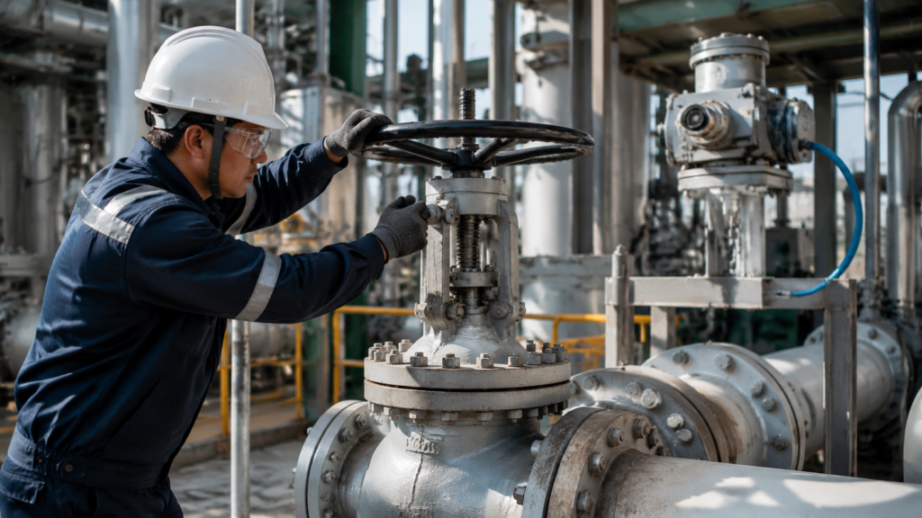
A valve torque curve is the main reference for actuator sizing. If the curve is read from only one value, the selected actuator may fail to open the valve, stop before full travel, or close without enough torque to achieve the required seat tightness. The opposite problem is also common: if a catalog value is multiplied by an extra safety factor without understanding whether the catalog value already includes a service margin, the actuator can become unnecessarily oversized. For quarter-turn ball valves, the torque curve should normally be read by stroke phase: break torque at initial opening, run torque during travel, and reseating torque near final closing. The exact relationship between these values is not universal. It depends on valve design, seat material, differential pressure, packing load, media, temperature, storage condition, and the actuator output curve. Balon, for example, states that its listed floating ball valve breakaway torque values do not contain service or safety factors and apply to standard seats controlling clean liquid or gas at ambient temperature. It also states that run torque is approximately 50% of breakaway torque and re-seat torque is approximately 75% of breakaway torque for that listed data set.[1] These ratios are useful as a manufacturer example, but they should not be treated as a universal rule for all ball valves. Torque item Valve phase Practical reference Main sizing role Break torque Opening from fully closed Usually the highest opening demand; must be taken from the exact valve and service condition Main opening benchmark for actuator sizing Run torque Continuous rotation after initial movement Often lower than break torque; manufacturer data can show values around 25%-50% or more depending on valve design Checks whether the actuator can continue moving the valve through the stroke Reseating torque Closing back into the seat Often lower than break torque, but can rise near the closing end; manufacturer examples may be around 75%, while some project data can be higher Confirms closing and sealing reliability Read the curve by stroke phase: opening peak, running load, and closing peak. Torque Components Break Torque Is Usually the Main Opening Peak Break torque is the torque needed at the moment the valve starts rotating from the fully closed position. In a floating ball valve, differential pressure pushes the ball against the downstream seat when the valve is closed. The actuator must overcome seat friction, stem packing friction, and any static adhesion before the ball starts moving. This is why break torque is normally higher than run torque. A high measured value on one valve size should not be generalized to the entire industry. For example, a DN80 floating ball valve under high differential pressure, high seat preload, special seat material, long idle time, or contaminated service can produce a much higher break torque than a clean-service catalog value. Published manufacturer data for a 3-inch floating ball valve can be far lower under standard clean liquid or gas service at ambient temperature.[1] Condition Possible torque effect Selection note Higher differential pressure Increases seat normal load and usually increases break torque Use the pressure point from the valve torque chart or test report Higher seat preload Can increase break torque and reseating torque Confirm preload assumptions with the valve manufacturer Low-emission packing Can increase stem friction if packing compression is high Use measured torque or packing torque limits, not a generic added value Long idle time Can increase first-cycle torque because of static adhesion Use a higher service factor or retest before installation For pipeline valves specified under API 6D, the actuator selection should be based on the valve design, pressure class, service condition, test documentation, and project torque data rather than an unsupported nominal value. API 6D defines requirements for pipeline valves, but the actual actuator sizing basis still needs the specific valve torque data and the applicable project conditions.[2] A practical sizing basis is: Use measured or manufacturer-confirmed break torque at the specified differential pressure. Confirm whether the torque value is raw torque or already includes service factors. Apply the selected application factor or safety factor only after the torque basis is clear. Check that the selected actuator does not exceed the valve stem maximum allowable torque. For product-specific data, use the valve manufacturer’s own torque table. For example, API 6D forged ball valve pages such as API 6D forged ball valves should be supported by torque data by bore size, pressure class, seat material, and service condition. Run Torque Is Lower but Still Must Be Checked Run torque is the torque required to keep the valve moving after the first movement has started. It is normally measured after the initial breakaway point, often after the first few degrees of travel. Run torque is usually lower than break torque because static friction has already been overcome. However, it is still important for actuator sizing. An actuator can have enough starting torque but still fail during travel if its continuous torque rating is too low. Balon’s floating ball valve torque data gives one manufacturer example: run torque is approximately one-half of breakaway torque for the listed standard-seat, clean-service conditions.[1] Other valve designs, seat materials, packing arrangements, and service conditions can produce different ratios. Run torque driver Effect on torque Recommended check Packing gland preload Excessive preload increases stem friction Verify packing compression procedure and measured torque during FAT Seat machining tolerance Uneven contact can create torque scatter across a batch Compare each unit against batch trend data Contamination or slurry Particles can increase friction and wear Use a severe-service factor and confirm seat material suitability Frequent operation Wear or packing degradation can change running torque over time Trend run torque during maintenance or partial-stroke testing ISO 15848-1 is often mentioned in low-emission valve projects, but it should be used correctly. ISO 15848-1 specifies testing procedures and a classification system for evaluating external leakage of valve stem seals, shaft seals, and body joints. It is not a universal source for added actuator torque. If low-emission packing is specified, the torque increase should
How to Select Valve End Connections for Industrial Pipelines | Flanged vs Buttweld vs Threaded
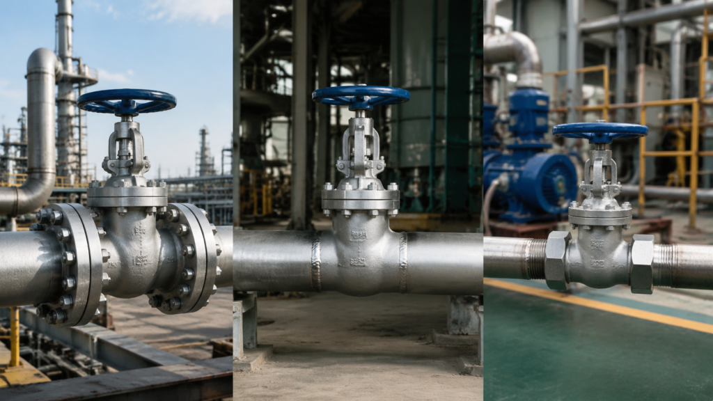
The choice of valve end connections in industrial pipelines directly affects sealing reliability, maintenance access, installation cost, and long-term safety. This article explains how to select flanged, buttweld, threaded, and clamp-type valve end connections for chemical plants, refineries, steam systems, hydrogen service, utility lines, and sanitary processes. The selection logic is based on commonly used piping and valve standards such as ASME B16.5 for pipe flanges, ASME B16.34 for valves, ASME B16.25 for buttwelding ends, ASME B31.3 for process piping, ASME PCC-1 for bolted flange joint assembly, ASME B1.20.1 for NPT threads, ISO 15848 for fugitive-emission testing, and project-specific engineering requirements. Connection Type Best Use Main Advantage Main Limitation Flanged General process lines, utility systems, maintenance points Easy disassembly and replacement Creates gasket and bolt-preload leakage paths Buttweld High-pressure, high-temperature, hydrogen, toxic, flammable, buried, or difficult-access service No gasketed end-joint leakage path Valve removal usually requires cutting and rewelding Threaded / NPT Small-bore auxiliary and low-risk service Compact and low cost Limited reuse reliability; sensitive to sealant, vibration, temperature, and installation quality Clamp Quick-Connect Sanitary, CIP/SIP, food, beverage, and pharmaceutical systems Very fast disassembly and cleaning Pressure and temperature limits depend strongly on clamp design and gasket material The correct valve end connection is not simply the cheapest option. It is the connection that matches design pressure, design temperature, leakage consequence, maintenance frequency, installation constraints, and applicable code requirements. Flanged Connections Raised Face vs Ring-Type Joint RF raised face and RTJ ring-type joint are common sealing face options for industrial valve flanges. The correct selection depends on pressure class, temperature, gasket type, leakage consequence, bolting control, and owner specifications. Item RF Raised Face RTJ Ring-Type Joint Common pressure class range Frequently used from Class 150 to Class 600; may also be used at higher classes where permitted by specification Frequently used from Class 600 upward in severe or high-pressure service Sealing method Soft, semi-metallic, or metallic gasket compression Metal ring gasket seating in machined grooves Typical application General refinery, chemical, water, steam, and utility service High-pressure steam, hydrogen, hydrocarbon, and severe-service applications Maintenance Gasket replacement is relatively simple Requires accurate groove condition, correct ring gasket, and controlled bolt loading RF flanges rely on gasket compression to fill surface irregularities and maintain sealing stress. RTJ flanges use a metallic ring gasket seated in a machined groove and are often selected where high pressure or severe leakage consequence makes gasketed RF sealing less desirable. ASME PCC-1 provides guidelines for pressure-boundary bolted flange joint assembly, including joint preparation, alignment, tightening practices, and gasket-stress control[1]. ISO 15848 fugitive-emission testing should not be used to qualify leakage at valve end connections, because ISO 15848-2 applies to external leakage from valve stems or shafts and body joints, while end-connection joints are excluded[2]. In one high-pressure steam valve review, an RF flange design showed gasket seating sensitivity during repeated assembly checks. Because the service involved elevated temperature, thermal cycling, and low tolerance for leakage, the engineering team evaluated RTJ as an alternative. The RTJ option reduced dependence on soft gasket recovery and provided a more robust sealing arrangement for the service. This type of result should be described as a project case example, not as an ISO 15848-2 Class A result. ISO 15848-2 is a fugitive-emission production acceptance test for valves and does not cover flange end-connection leakage. For Class 900 and above, or for services above about 350°C where leakage consequences are high, RTJ or buttweld ends should be evaluated instead of automatically selecting RF flanges. RTJ joints usually require more precise machining, correct ring-gasket selection, and better-controlled bolting practices than ordinary RF joints. Their initial cost is higher, but they can reduce leakage risk in severe services when correctly specified and assembled. For Class 600 and below in general process service, an RF flanged valve can provide a practical balance between cost, maintainability, and sealing performance. For high-pressure steam, hydrogen-rich media, or severe cyclic service, RTJ or buttweld ends should be evaluated during the valve specification stage. Further reading: CARILO API 6D Ball Valve Flange Specifications. ASME Pressure Classes from Class 150 to Class 2500 ASME pressure classes from Class 150 to Class 2500 cover most industrial flange and valve applications. The key rule is that pressure class must be checked at the actual design temperature and material group, not only at room temperature. Pressure Class Typical Use Approximate Rating at 38°C for Common Carbon Steel Group 1.1 Class 150 Low-pressure utility and general service About 1.96 MPa(g) Class 300 Medium-pressure process service About 5.11 MPa(g) Class 600 Refinery and chemical process service About 10.2 MPa(g) Class 900 High-pressure process and steam service About 15.3 MPa(g) Class 1500 Severe high-pressure service About 25.5 MPa(g) Class 2500 Very high-pressure severe service About 42.5 MPa(g) ASME B16.5 defines pressure-temperature ratings for pipe flanges and flanged fittings[3]. ASME B16.34 covers pressure-temperature ratings and other requirements for flanged, threaded, welding-end, and wafer-type valves[4]. Pressure-temperature ratings vary by material group and edition. Final selection must always be verified against the applicable standard edition and project design code. Material derating at elevated temperature is significant. For example, a Class 300 carbon steel flange rated around 5.1 MPa(g) at 38°C may have a lower allowable pressure at 260°C, 320°C, or 400°C. The exact value depends on the ASME edition, material group, and valve or flange standard used. On a chemical plant line with a design pressure of 2.5 MPa(g) and a design temperature around 260°C, Class 150 may appear acceptable if only ambient ratings are considered. However, after checking the pressure-temperature table at the actual design temperature and material group, Class 300 may be required to maintain adequate margin. Confirm the design pressure. Confirm the design temperature. Confirm the valve body and flange material group. Check the applicable ASME B16.5 or ASME B16.34 pressure-temperature table. Select the lowest class that safely covers both pressure and temperature, including project margin. Record the verification temperature and rating in the valve datasheet. A common specification mistake is selecting a pressure class based only on
Why Forged Ball Valves Outperform Cast 丨 Applications, Standards, and How to Verify a Forging
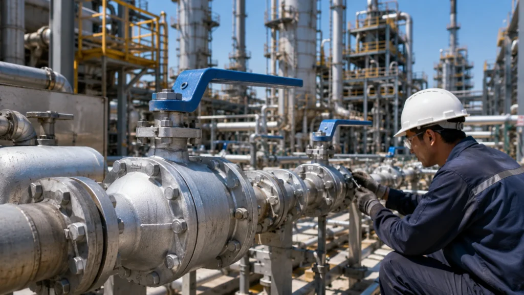
A procurement manager at an EPC firm once told me he’d been buying forged ball valves for fifteen years and had never seen a forging fail in service. Castings, yes. Weld-end valves, occasionally. But a properly forged body? Never. He wasn’t saying forgings are indestructible. He was saying that when the forging process is done right – proper reduction ratio, proper heat treatment, proper inspection – the failure modes that plague castings simply don’t exist. There’s no shrinkage porosity to find. No inclusions to act as crack initiation sites. No random grain structure that varies from thick sections to thin. Just continuous grain flow, uniform mechanical properties, and a predictable fatigue life. That’s what you’re buying when you specify a forged ball valve. Not a magic material. Not a guarantee against all possible failures. But a body whose quality is built into the manufacturing process itself, not verified after the fact by inspection that might miss something. Here’s what that means in practice – when you need it, what it costs, and how to make sure you’re getting what you paid for. The two things a forging guarantees that a casting can’t First: internal soundness. A properly forged body has no internal voids. The forging process mechanically works the steel under pressure, closing any porosity that existed in the original ingot. The resulting density is essentially 100% of theoretical. A casting, even a good one, has some level of microporosity. The question is whether it’s at a level that affects performance, not whether it exists. For most applications, properly inspected castings with porosity below the acceptance criteria perform fine. But for applications where any internal defect is unacceptable – high-pressure gas, cyclic loading, hydrogen service – the guaranteed soundness of a forging eliminates a failure mode that inspection can only manage, not eliminate. Second: directional grain flow. The forging process aligns the grain structure along the flow lines of the part. At a flange-to-body transition, the grain flow follows the contour of the radius, providing continuous load paths through the geometry. In a casting, the grain structure at that same transition is random, with grain boundaries oriented in all directions. Under cyclic pressure loading, cracks propagate along grain boundaries. A continuous grain flow forces the crack to cross grain boundaries, which requires more energy and takes more cycles. The fatigue life improvement is typically 15-20% for a forging compared to a casting of the same geometry and material. Forging vs. Casting: Key Differences Property Forging Casting Internal soundness No voids; ~100% density Some microporosity present Grain structure Continuous grain flow along part contours Random grain orientation Fatigue life improvement 15-20% better than casting Baseline When forged ball valves are mandatory – and when they’re overkill Class 900 and above: forged is standard. A Class 900 WCB carbon steel valve at 38°C sees 2,220 psi working pressure. The wall thickness for an 8-inch valve is about 38mm. The consequences of a body failure at this pressure are severe enough that the industry has standardized on forged bodies. I’ve seen specifications that allow cast bodies at Class 900 with 100% radiography and additional NDE, but these are exceptions, not the rule. Forged API 6D ball valves in Class 900 and 1500 are the default specification for pipeline and process plant isolation valves. Class 600: forged is preferred but not mandatory. A properly inspected cast body with 100% RT will perform adequately for most Class 600 applications. The decision typically depends on the service criticality and the end user’s material specification. Major oil companies often mandate forged at Class 600 as a blanket requirement in their valve specifications. Independent operators and EPC contractors focused on cost may accept cast with enhanced NDE. The cost difference is about 30-40% in favor of casting. For safety-critical isolation, emergency shutdown, and blowdown valves at Class 600, forged is worth the premium. Class 300 and below: forged is rarely necessary. The working pressures are low enough that a properly inspected cast body has ample design margin. Specifying forged at Class 300 adds cost without adding value. The exception is cyclic service – valves that cycle open and closed multiple times per day for years. The fatigue properties of a forging can extend service life in cyclic applications even at low pressure classes. Hydrogen service: forged is strongly recommended regardless of pressure class. Hydrogen embrittlement affects steel at the microstructural level, and the uniform grain structure of a forging provides better resistance than the variable structure of a casting. The forging’s lack of internal porosity also eliminates the hydrogen trapping sites that can cause blistering and cracking in castings exposed to high-pressure hydrogen. For hydrogen service at any pressure above about 300 psi, forged bodies are worth the cost premium. Forged ball valves for high-pressure gas service including hydrogen are increasingly specified as hydrogen blending and pure hydrogen pipelines become more common. What the ASTM standards actually require A105 is the standard forged carbon steel. The specification requires a minimum tensile strength of 485 MPa and minimum yield of 250 MPa. But those are minimums. A properly forged and normalized A105 body typically tests at 520-560 MPa tensile and 280-320 MPa yield. The difference between “meets the minimum” and “exceeds the minimum by 15-20%” is the difference between a forging that was properly worked and heat treated and one that barely met the specification. The mill certificate should show the actual test results, not just “conforms to A105.” If the results are right at the minimum, ask why. The forging ratio is not explicitly stated in A105. It’s implicit in the requirement that the forging be produced by a process that provides sufficient hot working to refine the grain structure. The industry standard is a minimum 3:1 reduction. Below that, the forging doesn’t develop full forging properties. This is why you can’t forge a 24-inch body from a 26-inch billet. The reduction ratio of 1.2:1 would produce a part with essentially the same grain structure as the
What Is an Industrial Ball Valve 丨 Types, Applications, and How to Choose the Right One
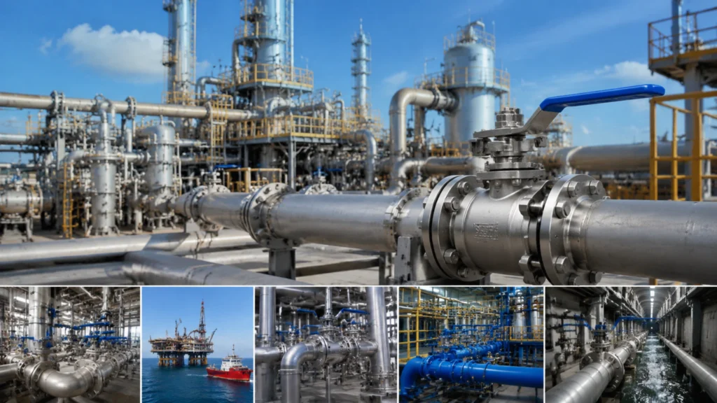
Walk into any refinery, chemical plant, or power station and count the valves. A medium-sized refinery has about 30,000 valves. Roughly 40% of them are ball valves. They are on cooling water lines, steam headers, product transfer lines, instrument air headers, and emergency shutdown systems. They range in size from half-inch instrument isolation valves to 42-inch pipeline isolation valves weighing over ten tons. They operate at pressures from near-atmospheric to 6,000 psi and temperatures from minus 196C to over 500C. The common thread: a ball with a hole through it, rotated 90 degrees, that stops or starts flow with a quarter turn. The industrial ball valve is the most widely specified quarter-turn valve in the world for a reason. It is simple and reliable. It seals tighter as the pressure increases, which is the opposite of most other valve types. It opens and closes in less than a second with a lever, or in a few seconds with an actuator. It is available from stock in virtually any size, material, and pressure class you could need. When properly specified and maintained, it can operate for decades without attention. Here is what an industrial ball valve actually is, how the different types work, and how to know which one you need. How a ball valve works in 30 seconds A ball valve has a spherical closure element—the ball—with a cylindrical hole bored through it. The ball sits between two seats inside a pressure-containing body. A stem passes through the top of the body and engages the ball. When the stem rotates 90 degrees, the ball rotates with it. When the bore aligns with the pipe, the valve is open. When the bore is perpendicular to the pipe, the valve is closed. That is it. There are no wedges to seat like a gate valve. There is no disc to lift like a globe valve. There is no clapper to swing like a check valve. It is just a ball that rotates. The simplicity has practical advantages. The 90-degree rotation means the valve opens and closes fast. A lever-operated 2-inch ball valve goes from fully closed to fully open in about a quarter of a second with a flick of the wrist. An actuated 12-inch ball valve takes 2 to 5 seconds depending on the actuator. Compare that to a gate valve of the same size, which might take 30 to 50 turns of a handwheel and 30 seconds to a minute to cycle. For emergency shutdown applications where speed matters, the ball valve’s quarter-turn operation is a critical advantage. Industrial ball valves are the standard isolation valve for process plants because their speed and reliability make them ideal for safety-critical applications. The self-energizing seal is the ball valve’s other key advantage. In a floating ball design, upstream pressure pushes the ball against the downstream seat. Higher pressure means tighter sealing. This is the opposite of a gate valve, where the sealing force comes from the wedge action and doesn’t increase with pressure. A ball valve that might weep slightly at 5 psi can seal bubble-tight at 500 psi. This makes ball valves the preferred choice for high-pressure gas service where positive shutoff is critical. Floating vs trunnion: the two ball valve architectures Every industrial ball valve falls into one of two categories based on how the ball is supported. The choice between them is determined primarily by valve size and pressure class. Floating Ball: The ball is not supported from below. It is held between two seats, and the stem engages it from above. Upstream pressure pushes the ball downstream against the seat to create the seal. This works well up to about 6 to 8 inches and Class 600. Trunnion Mounted: The ball is supported by upper and lower bearings (trunnions) that fix it in position. The seats are spring-loaded and press against the ball. This design scales to 60 inches and Class 2500 without excessive torque. In a floating ball valve, the stem has to transmit enough torque to rotate the ball against the friction of the loaded seat. Beyond 8 inches, this force becomes too large for the stem to overcome easily. Floating ball valves in carbon steel and stainless cover the size range from NPS 1/4 to NPS 8 for the vast majority of process plant applications. In a trunnion mounted ball valve, the trunnion bearings carry the pressure load. The stem only has to overcome the spring force on the seats and the friction in the bearings. Operating torque at 10 MPa on a 12-inch valve drops from over 1,800 Nm for a floating design to under 650 Nm for a trunnion design. Trunnion mounted industrial ball valves are the standard for pipeline service above 8 inches and Class 600. Here is the practical decision rule for choosing between them: Size and Pressure Class Recommended Design Reason Below 6 inches and Class 600 Floating is usually fine Torque requirements are manageable Above 8 inches or Class 600 Go with trunnion Torque is too high for floating design to handle efficiently Between 6 and 8 inches at Class 600 Depends on operating frequency Yearly cycling can be floating; daily cycling should be trunnion to reduce wear Full bore vs reduced port: the flow path decision Industrial ball valves come in full bore and reduced port configurations. Full bore: The ball opening matches the pipe ID. There is no restriction, no pressure drop, and you can pass pipeline inspection tools (pigs) through the valve. Reduced port: The ball opening is one pipe size smaller than the connection. This saves material cost and reduces operating torque, but creates a permanent restriction in the flow path. Full bore ball valves are mandatory on piggable pipelines, high-velocity gas lines, and slurry services. Reduced port is the standard for utility services where the pressure drop is negligible. The cost difference is about 15-25% in favor of reduced port. On a project with hundreds of valves, the savings from specifying reduced port
What Is an API 6D Ball Valve 丨 A Complete Guide for Engineers and Buyers
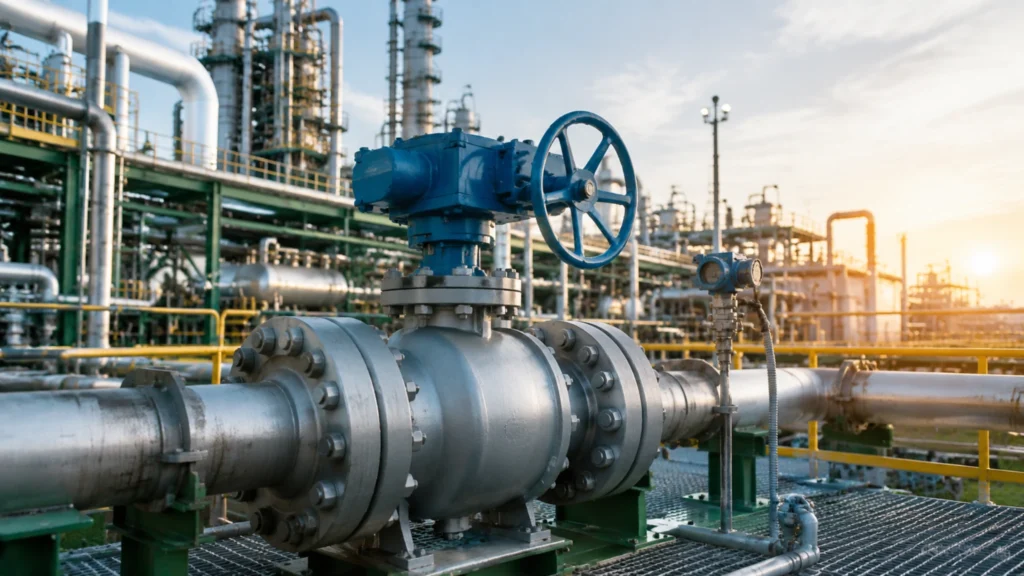
A few years ago, a project engineer at a gas pipeline company in Texas called me about a batch of 16-inch Class 600 ball valves that had just failed their site acceptance test. The valves were supposed to be API 6D compliant. They had the documentation. The nameplate said “API 6D.” But when the site inspector ran the hydro test at 1.5 times rated pressure, three out of twelve valves leaked at the stem. When he asked the manufacturer for the anti-blowout stem design verification records, they couldn’t produce them. The stems had been machined without the internal shoulder that API 6D requires. The valves were re-stamped with someone else’s certification number and shipped. The project was delayed four months while replacements were sourced from a different manufacturer. Total cost: roughly 2.1 million dollars in delays, rework, and expedited freight. API 6D is the most referenced standard for pipeline ball valves in the world, but I’ve learned over years of working with valve specifications that most people quoting the standard don’t actually know what it requires. They know it’s the pipeline valve standard. They know it’s what the datasheet asks for. But when you ask them what specific tests API 6D mandates, or what changed in the 2015 edition, or how it differs from API 608, you get blank stares. This is a problem because API 6D compliance isn’t a checkbox. It’s a detailed set of design, material, testing, and documentation requirements that directly affect whether your valve survives the first hydro test and the next twenty years of service. Here’s what API 6D actually means, in plain terms, without the standards-committee language that puts people to sleep. What API 6D actually covers (and what it doesn’t) API 6D is the Specification for Pipeline Valves. It covers gate, plug, ball, and check valves used in pipeline systems. It was first published in 1971 and has been revised multiple times, with the most significant update being the 24th edition in 2015, which was also adopted as ISO 14313. The 2015 edition made DBB and DIB configurations mandatory and completely revised the pressure-temperature rating tables for elevated temperatures up to 454°C. The standard covers valves from NPS 2 to NPS 60, Class 150 to Class 2500. It specifies design requirements, material requirements, testing and inspection procedures, marking, and documentation. It does not cover subsea valves (that’s API 17D), wellhead equipment (API 6A), or small-bore process valves (that’s API 608). If you’re specifying a ball valve for an onshore or offshore pipeline, compressor station, or refinery transfer line above NPS 4, API 6D is almost certainly what you need. API 6D ball valve manufacturers who are serious about the standard can produce full certification documentation for every pressure class from 150 to 2500. What API 6D covers vs other standards Standard Covers Size range Pressure class API 6D Pipeline gate, plug, ball, check valves NPS 2 – NPS 60 Class 150 – 2500 API 608 Metal ball valves for process piping NPS 24 max Class 600 max API 17D Subsea valves Various Various API 6A Wellhead equipment Various Various One thing people get wrong constantly: API 6D and API 608 are not interchangeable. API 608 covers metal ball valves for process piping in sizes up to NPS 24 and only up to Class 600. API 6D covers pipeline valves up to NPS 60 and Class 2500, with more stringent testing and documentation requirements. Chevron’s 2019 onshore pipeline specification actually mandates API 6D for all ball valves NPS 4 and above, replacing API 608 entirely at those sizes. If your project spec says “API 608” for a 12-inch Class 900 valve, it’s wrong. Someone copied the wrong standard number from an old datasheet. Pressure classes and the P-T curve nobody checks API 6D valves come in Class 150, 300, 600, 900, 1500, and 2500. But the Class number doesn’t tell you the working pressure. You need the pressure-temperature table for the specific material group per ASME B16.34. Typical working pressure for Class 300 WCB at various temperatures Temperature Working pressure (MPa) Working pressure (psi) 38°C (100°F) 5.1 740 260°C (500°F) 4.2 610 400°C (752°F) 2.8 400 That’s a 45% reduction in working pressure from ambient to 400°C. If you’re specifying a Class 300 valve for a 4 MPa steam line at 350°C, you’re right at the edge of the envelope with zero margin. I’ve seen plants operate valves at the P-T curve limit for years with no problem, and I’ve seen them crack at the body-to-bonnet joint because someone forgot that the process temperature spikes 30°C above normal during startup. The Class 2500 valves are in a different league entirely. Class 2500 WCB at ambient is rated for about 42 MPa. Beyond NPS 12, Class 2500 valves are typically custom-engineered with lead times that can stretch to 18 months. The valve body on a 12-inch Class 2500 trunnion ball valve can weigh over three tons. You don’t buy these off the shelf. API 6D pressure rating specifications need to be checked at the actual operating temperature, not the design temperature on the P&ID, because the P&ID doesn’t always account for process upsets. Every API 6D valve should come with a manufacturer’s P-T curve showing the maximum allowable working pressure at each temperature for that specific material group. If a manufacturer can’t produce this curve for your exact material and class, they don’t have a valid API 6D product. The curve is required by Section 7 of the standard. No curve, no compliance. The 2015 revisions that changed everything The 24th edition of API 6D in 2015 made two changes that affect every pipeline valve buyer. DBB and DIB mandatory: DBB (Double Block and Bleed) means the valve has two seating surfaces that, in the closed position, provide a seal against pressure from both ends of the valve, with a bleed between the seating surfaces. DIB (Double Isolation and Bleed) means each seat seals against pressure from one direction only, with a bleed between
What Is a Trunnion Mounted Ball Valve 丨 How It Works, When You Need One, and What to Look For
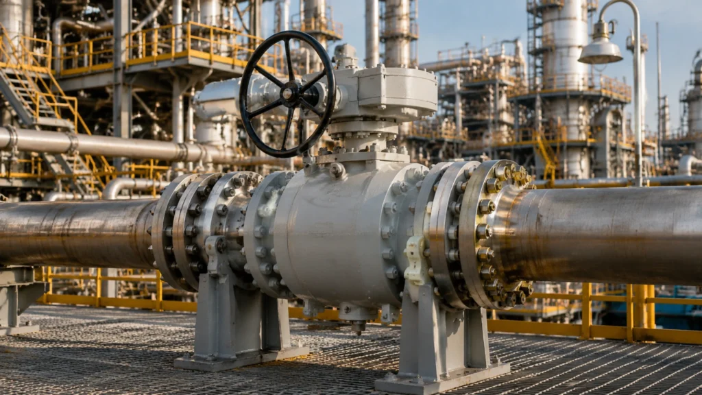
About ten years ago, I watched a crew try to close a 16-inch floating ball valve on a crude oil transfer line at 900 psi. The operator was a big guy, maybe 250 pounds, and he was hanging off the end of a four-foot cheater bar that was never supposed to be on that valve. The valve hadn’t been cycled in months. The ball was stuck against the downstream seat with about 180,000 pounds of force from the line pressure. He got it to move about ten degrees before the stem twisted. Not bent. Twisted. The square drive end of the stem sheared right at the keyway, and the valve was permanently jammed in a partially open position. They had to shut down the entire transfer line, drain 300 meters of 16-inch pipe, and cut the valve out. The replacement was a trunnion mounted ball valve of the same size and class. The operating torque dropped from “requires a cheater bar and a large human” to about 350 Nm, easily handled by a standard gear operator. Nobody ever installed a floating ball valve above 8 inches on that site again. Trunnion mounted ball valves solve a specific physics problem: when a ball valve gets big and the pressure gets high, the force on the ball becomes too large for a floating design to handle. The trunnion design fixes the ball in place with upper and lower bearings, so the line pressure pushes against the seats instead of pushing the ball into the downstream seat. This one design decision changes everything about how the valve performs at scale. It’s why virtually every pipeline ball valve above 8 inches and Class 600 is trunnion mounted. It’s why the torque stays manageable when the line pressure goes up. And it’s why the seats last five times longer in high-pressure service than they would in a floating design of the same size. Here’s how it works, when you actually need one, and how to not screw up the specification. How the trunnion design solves the force problem In a floating ball valve, the ball isn’t supported from below. It’s held between two seats, and when you pressurize the line, the ball floats downstream and presses against the downstream seat to create the seal. This works fine at small sizes and low pressures. At 4 inches and Class 300, the force on the ball is maybe a few thousand pounds, and the stem torque is under 100 Nm. You can operate it by hand. Scale that to 12 inches at Class 600 with 1,200 psi on the line. The ball has a projected area of about 113 square inches. At 1,200 psi differential, the force pushing the ball into the downstream seat is roughly 135,000 pounds. The friction between the ball and the seat at that force translates to a stem torque somewhere north of 2,000 Nm. That’s not hand-operable. That’s not even gear-operable without a massive gearbox. And if the valve has been sitting in one position for months, the seats can stick to the ball, and the breakaway torque can be double the running torque. A trunnion mounted ball valve fixes the ball with an upper stem bearing and a lower trunnion bearing. The ball can rotate, but it can’t translate downstream. The seats are spring-loaded, so they press against the ball rather than the ball pressing against them. The friction that creates operating torque comes from the spring force on the seat, not from the line pressure on the ball. At 12 inches and Class 600, the operating torque drops from over 2,000 Nm to around 350-450 Nm. That’s gear-operable with a standard worm gear drive. API 6D trunnion mounted ball valves in sizes up to NPS 48 and Class 2500 use this design because it’s the only way to make a valve that size both sealable and operable. The spring-loaded seats have another advantage: they maintain contact with the ball even as the seats wear. In a floating design, as the downstream seat wears, the ball moves further downstream to maintain contact, and the stem packing sees increasing side load. Eventually the packing deforms, the stem starts leaking, and you’re replacing the packing and possibly the stem. In a trunnion design, the spring-loaded seats take up the wear without affecting stem alignment. Seat replacement intervals on a trunnion valve are typically five to seven times longer than on a floating valve of the same size in the same service. When you need a trunnion mounted valve and when you don’t The industry rule of thumb is simple: above 6 inches or above Class 600, go trunnion. Below that, floating is fine. But like most rules of thumb, there are exceptions. Below 6 inches but high class: If your application is below 6 inches but you’re at Class 900 or 1500, the forces are high enough that a trunnion design makes sense even at small sizes. A 4-inch Class 1500 floating valve at 3,700 psi line pressure has about 46,000 pounds of force on the ball. The stem sees enough torque that you need a gear operator anyway. At that point, the trunnion design gives you lower torque and longer seat life for a marginal cost increase. Class 300 to 600, below 8 inches, clean service: If you’re at Class 300 to 600 and below 8 inches in clean service with infrequent cycling, a floating valve is usually the right choice. It’s cheaper, simpler, and perfectly adequate. Don’t over-specify a trunnion valve for a 4-inch Class 150 cooling water line. The valve will work fine, but you’ll pay 40-60% more than you need to. Full bore for pigging: If you need full bore for pigging, trunnion mounted is the standard above 4 inches. Full bore floating ball valves exist, but they get heavy fast because the ball diameter scales with the bore, and a larger ball means more surface area for the line pressure to push against. A full bore 8-inch
What Is a Side Entry Ball Valve 丨 Two-Piece vs Three-Piece, Maintenance, and Fire-Safe Design
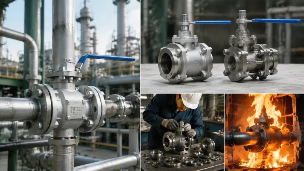
A few years ago, I was on a platform in the North Sea where a 16-inch Class 900 trunnion ball valve had developed a seat leak. The valve was a side entry design with a bolted two-piece body. The leak had been caught during a routine quarterly cavity vent check – pressure was building in the valve body cavity when it shouldn’t have been, which meant at least one seat was letting gas past the ball. Normally, fixing a seat leak on a valve that size means cutting the valve out of the line and shipping it to a workshop, which means a shutdown that costs hundreds of thousands of dollars a day. But because this valve was a side entry design, the maintenance crew was able to unbolt the body flange, remove the entire internal assembly – ball, seats, stem, everything – and replace the seats with the valve body still welded into the pipeline. Total downtime from isolation to back in service: 14 hours. The alternative – cutting out a welded-body valve and replacing it – would have been five to seven days. That’s why side entry exists. Side entry ball valves aren’t talked about as much as floating and trunnion designs, but the body construction style matters as much as the ball support mechanism. The side entry design is the dominant body style for pipeline ball valves above about 4 inches, and the reason is simple: maintainability. Here’s how it works, what the options are, and when it’s the right choice. What a side entry ball valve actually is A side entry ball valve has a body that splits into two or three pieces along a plane perpendicular to the pipe axis. The ball, seats, stem, and all internal components are installed from the side – that is, from one end of the valve body – and then the body pieces are bolted together to form the pressure-containing envelope. The split plane goes through the ball cavity, so when you unbolt the body and separate the pieces, you have direct access to the ball, both seats, and the stem. This is completely different from a top entry valve, where the bonnet comes off the top and the internals are removed through the top of the body without disturbing the pipeline connections. Top entry exists for the same reason – maintainability without cutting the valve out of the line – but it requires vertical clearance above the valve and a heavier, more expensive body casting. Side entry is simpler, cheaper, and easier to manufacture, which is why it’s the default body style for the vast majority of API 6D pipeline ball valves from NPS 2 to NPS 48. Side entry ball valves in two-piece and three-piece bolted configurations cover the entire range of pipeline valve applications from Class 150 to Class 2500. The gasket between the body pieces is the critical sealing element in a side entry valve. It has to contain the full line pressure without leaking, survive temperature cycles that expand and contract the body at different rates from the bolting, and maintain its seal for decades without replacement. The three most common gasket types are: Spiral-wound stainless steel with graphite filler for general service Ring-type joint metal gaskets for Class 900 and above Pressure-energized lip seals for applications where fire-safe certification requires a graphite seal that won’t burn out If the body gasket fails, the valve leaks to atmosphere at the split line, and the repair requires depressurizing the line and re-torquing or replacing the gasket. This is rare on a properly assembled valve, but it’s the one failure mode that a side entry valve has that a welded-body valve doesn’t. Two-piece vs three-piece bolted construction Side entry ball valves come in two-piece and three-piece configurations, and the difference affects both cost and maintainability. Two-piece design A two-piece side entry valve has one body piece that contains the upstream connection and half the ball cavity, and a second piece that contains the downstream connection and the other half of the ball cavity. The two pieces bolt together with a single gasket between them. The ball, seats, and stem are assembled into one body half, the gasket is placed, and the second body half is bolted on. This is the simplest and cheapest side entry configuration. It’s the standard for pipeline valves from NPS 2 to NPS 24 in Class 150 through 900. The limitation of a two-piece design is that to remove the internals, you have to completely separate the two body halves, which means you need enough axial clearance to pull one body half back by at least the length of the ball assembly. On a 16-inch valve, that’s about 18 to 24 inches of axial movement. In a tightly packed pipe rack, that clearance might not exist. If the valve is between two fixed flanges with nowhere to move the pipe, a two-piece body can’t be serviced in place – you have to cut it out. Three-piece design A three-piece side entry valve solves this with a center body section that contains the ball and seats, and two end connectors that remain bolted to the pipeline. To service the valve, you unbolt the end connectors from the center body, spread them apart just enough to extract the center body section – typically 6 to 8 inches of movement – and pull the entire ball and seat assembly out with the center body. The end connectors stay attached to the pipe. This requires far less axial clearance than a two-piece design and is standard for valves that are expected to need in-line maintenance, such as refinery isolation valves and compressor station valves. The tradeoff is that three-piece valves cost about 20-30% more than equivalent two-piece valves because they have more machined parts, more bolting, and an additional gasket. They’re also heavier because the center body section has to be thick enough to handle the full bolting load from both end connectors. A 12-inch
What Is a Reduced Port Ball Valve 丨 When It Is the Smart Choice and When It Will Cost You More Than You Saved
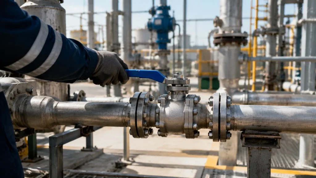
A project engineer at a chemical plant once showed me two quotes for 200 4-inch Class 300 ball valves. The full bore quote was 112,000 dollars. The reduced port quote was 87,000 dollars. A 25,000-dollar difference on one valve type alone. The plant had about 800 ball valves total across all sizes and classes. The engineer was applying reduced port everywhere except on the three lines that needed pigging and the two high-velocity gas lines where pressure drop mattered. Total saving across the project: roughly 85,000 dollars. Five years later, not one of those reduced port valves had caused a problem. The utility water valves, the instrument air valves, the lube oil valves – all running fine with reduced port. The money saved went toward upgrading the Class 900 isolation valves on the reactor feed lines from cast to forged bodies. That’s the right way to use reduced port. Reduced port ball valves are not the cheap alternative to full bore. They’re the correct choice for the majority of industrial ball valve applications, and specifying full bore everywhere is engineering waste. Here’s what reduced port means, when it’s the right call, and how to avoid the applications where it’ll cost you far more than you saved. What reduced port actually means A reduced port ball valve has a ball opening diameter that’s one or two nominal pipe sizes smaller than the valve’s end connection size. A 4-inch reduced port valve typically has a ball opening equivalent to a 3-inch pipe. A 6-inch reduced port valve has a roughly 4-inch opening. A 12-inch reduced port valve has a 10-inch opening. The standard reduction is one pipe size, though some manufacturers offer two-size reductions for larger valves where the cost saving is larger. The reduced port design saves material in two places: the ball itself is smaller, which reduces the amount of metal in the most expensive machined component, and the body cavity can be smaller because it only has to accommodate the smaller ball. A 6-inch Class 300 reduced port valve with a 4-inch ball weighs about 15-20% less than the full bore version with a 6-inch ball. The cost saving comes from less raw material, less machining time on the ball and body, and a lighter finished product that costs less to ship. The tradeoff is a permanent restriction in the flow path. When fluid enters the valve, it passes through the full-diameter end connection, then encounters the smaller ball opening. The flow accelerates through the restriction and then decelerates as it expands back into the downstream pipe. This acceleration and deceleration creates turbulence that dissipates energy as heat, which manifests as a pressure drop across the valve. For most applications, that pressure drop is too small to matter. For a few specific applications, it’s a deal-breaker. Reduced port ball valves are the standard specification for utility and secondary process services where the flow restriction is acceptable. The math of the pressure drop The pressure drop across a reduced port valve is predictable. For liquid service, the pressure drop is proportional to the velocity squared and inversely proportional to the port diameter. 6-inch valve with 4-inch reduced port, water at 10 ft/s: pressure drop ~0.3 to 0.5 psi. At 20 ft/s: pressure drop quadruples to 1.2 to 2.0 psi. Gas service (e.g. natural gas at 50 ft/s and 800 psi): pressure drop can be 3 to 8 psi. Over a short pipe run with one valve, this is negligible. Over a 50-mile transmission line with valves every 5 miles, ten reduced port valves with 5 psi drop each adds 50 psi of cumulative pressure loss. That 50 psi translates to additional compression horsepower at the upstream station, which costs real money in fuel or electricity every hour the line operates. Pressure drop across reduced port valves becomes economically significant on long pipelines and high-velocity gas service, and insignificant on short process piping runs. The Cv – the flow coefficient – quantifies this. Valve Type Size Cv Full bore ball valve 6-inch About 2,500 Reduced port version 6-inch About 1,000 The Cv is the flow rate in US gallons per minute of 60°F water that creates a 1 psi pressure drop. The higher the Cv, the lower the pressure drop for a given flow rate. The reduced port valve has 60% less flow capacity than the full bore version at the same pressure drop. Or, for the same flow rate, the reduced port valve creates about 2.5 times the pressure drop. The question is whether that matters for the specific application. Where reduced port is the smart choice For the vast majority of industrial ball valve applications, reduced port is the correct specification. The cost saving is real, the pressure drop is negligible, and there’s no operational penalty. Utility water systems. Cooling water, fire water, potable water, washdown water. These lines run at low velocity – typically 5 to 10 ft/s – and the pressure drop across a single reduced port valve is a fraction of a psi. A 6-inch reduced port valve on a cooling water line at 8 ft/s loses about 0.4 psi. The pump discharge pressure might be 60 psi. Nobody will ever notice that 0.4 psi. Instrument air and nitrogen. Clean, dry gases at moderate pressure – typically 80 to 120 psi. Flow rates are low. The valve is typically fully open or fully closed, never throttled. The pressure drop across a reduced port valve is negligible, and the cost saving on large instrument air headers with multiple isolation valves adds up fast. Lube oil and seal oil systems. Low-velocity liquid services where the valve is either open or closed and the flow rate is determined by pumps and orifices downstream. The pressure drop across the valve is a few tenths of a psi at most. Full bore adds cost and weight with no operational benefit. Steam condensate return. Low pressure, moderate temperature, and the valve cycles infrequently. Reduced port saves money and the pressure drop
What Is a High Pressure Ball Valve 丨 Design Limits, Material Requirements, and Testing Beyond the Minimum
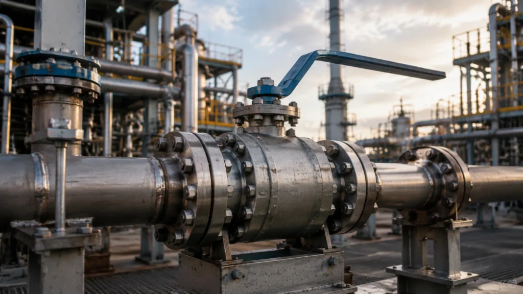
A pipeline operator in West Texas called me a few years ago about a smart pig that had gotten stuck. The pipeline was a 12‑inch crude oil line, Class 600, running about 40 miles between a gathering station and a central processing facility. The pigging operation was routine – they ran pigs every three months to clear paraffin buildup from the pipe wall. This particular pig had made it about 22 miles and then stopped. The pressure upstream of the pig was climbing, and the pressure downstream was dropping, which meant the pig was stuck, not just slow. They spent two days trying to free it with pressure pulsing before they had to shut down the line and dig. When they cut out the section of pipe where the pig had stopped, they found the problem: a reduced bore ball valve. The valve was 12‑inch flanged, Class 600, same as the pipe. But the ball opening was 10 inches instead of 12. The pig had entered the reduced opening, wedged itself into the 2‑inch diameter reduction, and locked solid. The valve had been in the line for years and nobody knew it was reduced bore because the external dimensions and flange size were identical to the rest of the valves on the line. It had been installed before the pigging program started, when someone saved about 800 dollars per valve by specifying reduced bore instead of full bore. The cost of the shutdown, excavation, pipe cutting, valve replacement, and two days of lost production: about 340,000 dollars. Full bore ball valves exist for one reason: to eliminate the diameter change inside the valve that creates a restriction, a pressure drop, and an obstacle to anything that needs to pass through the pipeline. The full bore design makes the ball opening match the pipe’s internal diameter exactly, so there’s no step change in cross‑section at the valve. For some applications, this is a convenience. For others, it’s a hard operational requirement that determines whether the pipeline can function as designed. Here’s when you need it, when you don’t, and what you’re paying for either way. What full bore actually means A full bore ball valve has a ball port diameter that matches the internal diameter of the connecting pipe. For a 12‑inch Schedule 80 pipe with an ID of 11.75 inches, a full bore valve has a ball opening of 11.75 inches, give or take a small tolerance. The API 6D tolerance for full bore valves is that the ball port diameter shall be not less than the specified minimum bore, which for most pipeline valves is the pipe ID minus a small manufacturing allowance. A reduced bore ball valve has a ball port one or two pipe sizes smaller than the connection size. A 12‑inch reduced bore valve typically has a 10‑inch ball opening. The external dimensions and flange size are the same as the full bore version. From the outside, the valves look identical. The only way to tell the difference without disassembling the valve is to measure the bore with a caliper through the end connection, or to check the manufacturer’s datasheet. Full bore forged ball valves are specified by the bore diameter as well as the connection size precisely because reduced bore valves can hide in plain sight. The full bore design adds cost, weight, and in some cases stem torque. The ball is physically larger because the bore is larger. A 12‑inch full bore ball is about 30% heavier than a 12‑inch reduced bore ball of the same material. The larger ball requires a larger body cavity, which means more metal in the body. The larger ball also has a higher moment of inertia, which increases the stem torque slightly. Property Full bore vs. reduced bore (12‑inch) Cost 15–25% more Weight 15–20% more Ball weight increase ~30% heavier But the full bore eliminates two problems that the cost saving of reduced bore creates: the permanent pressure drop across the valve, and the inability to pass pipeline inspection tools through the line. The value of those two things depends entirely on the application. Pigging: the application that makes full bore non‑negotiable Pipeline pigging is the single biggest driver of full bore ball valve specification. A pig – a Pipeline Inspection Gauge – is a device that travels through the pipeline to clean the pipe wall, remove accumulated deposits, separate different products in a multi‑product pipeline, or inspect the pipe condition with sensors. Pigs are sized to fit the pipe ID with a slight interference fit so they scrape the wall effectively. When a pig encounters a reduced bore valve, the diameter reduction wedges the pig in the valve, and the line stops. There are three types of pigging operations that require full bore valves: Cleaning pigs – remove wax, scale, and debris from the pipe wall. They have wire brushes or scraper blades that engage the pipe ID with significant force. A cleaning pig that hits a 2‑inch diameter reduction at 10 ft/s is going to stop hard, and it’s not going to free itself with pressure pulsing. Batching pigs – separate different products in a multi‑product pipeline (crude oil followed by diesel, for example). These pigs are typically foam or cup‑type designs that form a tight seal against the pipe wall. A batching pig that loses its seal at a reduced bore valve allows product mixing, which can ruin an entire batch. Intelligent pigs – carry inspection sensors (magnetic flux leakage, ultrasonic, or caliper tools) that measure the pipe wall thickness and detect corrosion and cracks. An intelligent pig that encounters a reduced bore valve can damage its sensor array on the abrupt diameter change, destroying an inspection tool that costs 50,000 to 200,000 dollars. API 6D full bore ball valves for pipeline service are mandatory on any line that operates a pigging program. The rule for pigging is simple: every valve on a piggable pipeline must be full bore, and the transition from the pipe
