
What Is a Full Bore Ball Valve 丨 When You Need It, When You Do not, and the Pigging Requirement Most People Learn the Hard Way
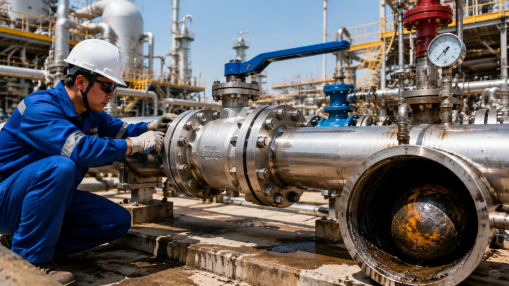
A pipeline operator in West Texas called me a few years ago about a smart pig that had gotten stuck. The pipeline was a 12‑inch crude oil line, Class 600, running about 40 miles between a gathering station and a central processing facility. The pigging operation was routine – they ran pigs every three months to clear paraffin buildup from the pipe wall. This particular pig had made it about 22 miles and then stopped. The pressure upstream of the pig was climbing, and the pressure downstream was dropping, which meant the pig was stuck, not just slow. They spent two days trying to free it with pressure pulsing before they had to shut down the line and dig. When they cut out the section of pipe where the pig had stopped, they found the problem: a reduced bore ball valve. The valve was 12‑inch flanged, Class 600, same as the pipe. But the ball opening was 10 inches instead of 12. The pig had entered the reduced opening, wedged itself into the 2‑inch diameter reduction, and locked solid. The valve had been in the line for years and nobody knew it was reduced bore because the external dimensions and flange size were identical to the rest of the valves on the line. It had been installed before the pigging program started, when someone saved about 800 dollars per valve by specifying reduced bore instead of full bore. The cost of the shutdown, excavation, pipe cutting, valve replacement, and two days of lost production: about 340,000 dollars. Full bore ball valves exist for one reason: to eliminate the diameter change inside the valve that creates a restriction, a pressure drop, and an obstacle to anything that needs to pass through the pipeline. The full bore design makes the ball opening match the pipe’s internal diameter exactly, so there’s no step change in cross‑section at the valve. For some applications, this is a convenience. For others, it’s a hard operational requirement that determines whether the pipeline can function as designed. Here’s when you need it, when you don’t, and what you’re paying for either way. What full bore actually means A full bore ball valve has a ball port diameter that matches the internal diameter of the connecting pipe. For a 12‑inch Schedule 80 pipe with an ID of 11.75 inches, a full bore valve has a ball opening of 11.75 inches, give or take a small tolerance. The API 6D tolerance for full bore valves is that the ball port diameter shall be not less than the specified minimum bore, which for most pipeline valves is the pipe ID minus a small manufacturing allowance. A reduced bore ball valve has a ball port one or two pipe sizes smaller than the connection size. A 12‑inch reduced bore valve typically has a 10‑inch ball opening. The external dimensions and flange size are the same as the full bore version. From the outside, the valves look identical. The only way to tell the difference without disassembling the valve is to measure the bore with a caliper through the end connection, or to check the manufacturer’s datasheet. Full bore forged ball valves are specified by the bore diameter as well as the connection size precisely because reduced bore valves can hide in plain sight. The full bore design adds cost, weight, and in some cases stem torque. The ball is physically larger because the bore is larger. A 12‑inch full bore ball is about 30% heavier than a 12‑inch reduced bore ball of the same material. The larger ball requires a larger body cavity, which means more metal in the body. The larger ball also has a higher moment of inertia, which increases the stem torque slightly. Property Full bore vs. reduced bore (12‑inch) Cost 15–25% more Weight 15–20% more Ball weight increase ~30% heavier But the full bore eliminates two problems that the cost saving of reduced bore creates: the permanent pressure drop across the valve, and the inability to pass pipeline inspection tools through the line. The value of those two things depends entirely on the application. Pigging: the application that makes full bore non‑negotiable Pipeline pigging is the single biggest driver of full bore ball valve specification. A pig – a Pipeline Inspection Gauge – is a device that travels through the pipeline to clean the pipe wall, remove accumulated deposits, separate different products in a multi‑product pipeline, or inspect the pipe condition with sensors. Pigs are sized to fit the pipe ID with a slight interference fit so they scrape the wall effectively. When a pig encounters a reduced bore valve, the diameter reduction wedges the pig in the valve, and the line stops. There are three types of pigging operations that require full bore valves: Cleaning pigs – remove wax, scale, and debris from the pipe wall. They have wire brushes or scraper blades that engage the pipe ID with significant force. A cleaning pig that hits a 2‑inch diameter reduction at 10 ft/s is going to stop hard, and it’s not going to free itself with pressure pulsing. Batching pigs – separate different products in a multi‑product pipeline (crude oil followed by diesel, for example). These pigs are typically foam or cup‑type designs that form a tight seal against the pipe wall. A batching pig that loses its seal at a reduced bore valve allows product mixing, which can ruin an entire batch. Intelligent pigs – carry inspection sensors (magnetic flux leakage, ultrasonic, or caliper tools) that measure the pipe wall thickness and detect corrosion and cracks. An intelligent pig that encounters a reduced bore valve can damage its sensor array on the abrupt diameter change, destroying an inspection tool that costs 50,000 to 200,000 dollars. API 6D full bore ball valves for pipeline service are mandatory on any line that operates a pigging program. The rule for pigging is simple: every valve on a piggable pipeline must be full bore, and the transition from the pipe
What Is a Forged Ball Valve 丨 Why Grain Structure Matters, When to Choose Forged Over Cast, and How to Verify You Got One
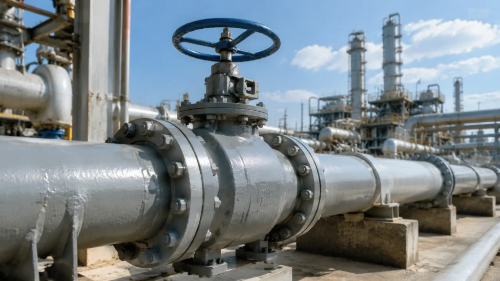
A few years ago I was called in to investigate a Class 900 10-inch ball valve that had cracked at the body during a hydro test. The valve was supposed to be forged A105 steel. The test pressure was 3,330 psi – standard 1.5 times the Class 900 rated pressure of 2,220 psi. The crack originated at an internal corner radius in the body cavity and propagated through the wall in about two seconds. Fortunately, nobody was standing close. When we sectioned the body, the fracture surface told the story immediately. The grain structure was coarse, random, and contained internal porosity. This was a casting. Someone had machined a cast body, stamped it with an A105 forging heat number, and shipped it. The casting had passed the visual inspection because the outside looked fine. Under load, the internal porosity created stress concentrations that the forged grain structure would have avoided. The foundry that made the casting had no record of the heat, and the PMI reading on the body confirmed the chemistry was close to A105 but the silicon content was off – typical for a WCB casting, but wrong for A105 forging. The entire batch of sixteen valves from that supplier was rejected. Forged ball valves exist for a reason: when the pressure gets high enough, the grain structure of the steel matters. A forged body has a continuous grain flow that follows the contour of the part, giving it 15–20% higher fatigue strength than an equivalent cast body and eliminating the internal voids that can exist in a casting. For Class 600 and above, forged bodies are the standard for good reason. Here’s what forged actually means, when it matters, and when you can save money by using cast instead. What forging does to steel that casting can’t Steel starts as an ingot. In a casting, the ingot is melted, poured into a mold, and cooled. The grain structure is random. The cooling rate varies depending on the thickness of the mold wall and the section thickness of the part. Thick sections cool slowly and develop large grains. Thin sections cool quickly and develop fine grains. At section transitions – where a thick flange meets a thinner body wall – the grain structure changes abruptly, and that’s where stress concentrates under load. In a forging, the ingot is heated to about 1,150°C and mechanically worked under pressure in a forge press. The working process – hammering or pressing the steel into shape – breaks up the as-cast grain structure and aligns the grains along the flow lines of the part. The mechanical working also closes internal voids and porosity that existed in the original ingot. The result is a body with a uniform grain structure, oriented along the stress paths that the valve will see in service, with an internal porosity level below 0.001%. API 6D forged ball valves in full bore configuration achieve the highest pressure integrity because the grain flow in a forging matches the hoop stress pattern around the bore. The ASTM standards spell out the difference. A105 is the standard forged carbon steel for valve bodies. Minimum tensile strength 485 MPa, yield strength 250 MPa, elongation 22% minimum. The forging ratio – the ratio of the original ingot cross-section to the final part cross-section – must be at least 3:1 to achieve these properties. Below 3:1, the mechanical working is insufficient to break up the as-cast structure, and the forging has properties closer to a casting than a true forging. This is why you can’t forge a 24-inch body from a 26-inch ingot and call it a forging. The geometry doesn’t provide enough reduction to refine the grain structure. WCB cast carbon steel has similar tensile strength – 485–655 MPa – but the yield strength is slightly higher at 250 MPa minimum, and the elongation is the same at 22%. The difference isn’t in the static properties. It’s in the fatigue properties and the consistency. A forging will have uniform properties throughout the part because the grain structure is uniform. A casting will have property variations depending on section thickness and cooling rate. The fatigue limit of A105 forged steel is typically 10–15% higher than WCB cast steel of the same nominal composition, and the scatter in fatigue test results is much lower for forgings because there are no random casting defects to act as crack initiation sites. Key differences between A105 forged and WCB cast carbon steel Property A105 (Forged) WCB (Cast) Tensile strength (MPa) 485 min 485–655 Yield strength (MPa) 250 min 250 min Elongation 22% min 22% min Fatigue limit Baseline (10–15% higher than cast) Lower (more scatter) Internal porosity < 0.001% Can exist (shrinkage, hot tears) Grain structure Uniform, aligned with stress paths Random, varies with section thickness Silicon content (typical) 0.15–0.35% 0.60% max (often higher) Forging ratio required ≥ 3:1 N/A When forged makes a real difference The practical rule: Forged bodies for Class 600 and above. Cast bodies for Class 300 and below. Class 600 is the gray zone where both are used depending on the application. At Class 150 and 300, the working pressures are low enough that a properly inspected cast body has plenty of margin. A Class 300 WCB valve at 38°C sees 740 psi. The wall thickness per ASME B16.34 is conservative for cast material. There’s no reason to pay the forging premium unless the service conditions are aggressive in some way other than pressure – extreme thermal cycling, for instance, where the superior fatigue properties of a forging might matter. At Class 600, the working pressure at 38°C is 1,480 psi. The wall thickness goes up about 50% from Class 300. The forces on the body are higher, the bolting loads are higher, and the consequences of a body failure are more severe. This is where the industry splits. Some buyers specify forged at Class 600 as a blanket requirement. Others accept cast with 100% radiographic inspection. Both approaches can work. The
What Is a Floating Ball Valve 丨 How It Works, Where It Excels, and When to Upgrade to Trunnion
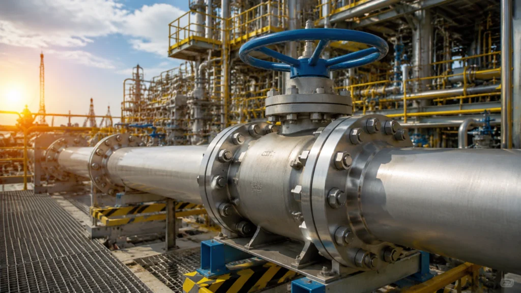
I once had a plant manager call me about a 3-inch floating ball valve on a steam condensate return line. The valve was PTFE-seated, Class 300, had been in service for about four years, and was leaking steam from the stem at maybe 20 drips per minute. He wanted to know if he should replace it with the same thing or upgrade. I asked two questions: what’s the actual operating temperature at the valve, and how many times a day does it cycle? Temperature was 195C. Cycles: about 40 per day, every day, for four years. Quick math: that’s roughly 58,000 cycles on a valve that was technically rated for the temperature but with PTFE seats that start cold-flowing above 180C under cyclic load. The valve had done its job for four years without a failure. That’s actually impressive. We replaced it with a PEEK-seated floating valve of the same size and class, set the packing to live-loaded with Belleville springs, and four years later it was still running with zero visible stem leakage. The valve cost about 380 dollars. The upgrade from PTFE to PEEK added about 90 dollars. Total cost difference over eight years of service: 90 dollars. Value of not having a steam leak in a crowded mechanical room: immeasurable. Floating ball valves don’t get the engineering respect they deserve. They’re the workhorse of small-bore industrial piping. Simple design, low cost, reliable when applied within their limits. The problems happen when people use them outside those limits, which happens constantly because the limits aren’t always obvious from the datasheet. Here’s what a floating ball valve actually is, where it works, where it doesn’t, and how to not be the person who put a 10-inch floating valve on a 900 psi gas line. How the floating ball design works A floating ball valve has exactly three pressure-containing moving parts: the ball, and two seats. That’s it. The ball sits between the seats with no lower support. The stem passes through the top of the body and engages the ball through a rectangular or slotted drive. When the valve is closed and the line is pressurized, the upstream pressure pushes the ball downstream against the downstream seat, and that contact pressure creates the seal. The simplicity is the genius. No trunnions. No bearings. No spring-loaded seat assemblies. The line pressure itself creates the sealing force. Higher pressure means tighter sealing, at least until the force exceeds what the seat material can handle. This self-energizing seal is why floating ball valves seal better at high pressure than at low pressure, which is the opposite of most valve designs. But that simplicity also creates the design’s fundamental limitation. The entire pressure load on the ball is transmitted through the stem to the stem bearings. As the ball gets bigger, the surface area that pressure acts on grows with the square of the diameter. A 4-inch ball at 300 psi has about 3,800 pounds of force pushing it into the downstream seat. An 8-inch ball at 300 psi has about 15,000 pounds. A 10-inch ball at 600 psi has about 47,000 pounds. The stem has to transmit all of that as torque to rotate the ball against the friction of the loaded seat. At some point, the stem cross-section can’t handle it, and either the operator can’t turn the valve or the stem twists off at the drive connection. This is why the practical limit for floating ball valves is about 6 to 8 inches and Class 600. Beyond that, the stem torque becomes unmanageable, and you need a trunnion design where the trunnion bearings take the pressure load instead of the stem. Where floating ball valves are the right choice Floating ball valves dominate small-bore industrial piping for good reasons: They’re cheaper than trunnion valves of the same size. They have fewer parts, which means fewer things that can fail. They seal tighter at high pressure because the line pressure increases the seat contact force. They’re available from stock at virtually any industrial valve supplier in sizes from 1/4 inch to 6 inches across all common pressure classes. The sweet spot is NPS 1/2 to NPS 4 in Class 150 to Class 300. This covers the vast majority of process piping in refineries, chemical plants, power stations, and commercial HVAC. A 2-inch Class 300 floating ball valve with PTFE seats, carbon steel body, and stainless trim costs about 150 to 300 dollars in bulk quantities and will last 10 to 15 years in clean service. That’s a cost per year of service that’s hard to beat with any other valve type. Carbon steel vs stainless floating valve selection usually comes down to the process fluid: WCB carbon steel for hydrocarbons and non-corrosive water, CF8M 316 stainless for chemicals and seawater. For on-off isolation in utility systems, floating ball valves are the default choice for a reason. Cooling water, instrument air, nitrogen purge, lube oil, fuel gas to burners. These services don’t need the zero-leakage of a trunnion valve’s spring-loaded seats, and they don’t need the torque margin that trunnion bearings provide. A properly sized floating ball valve in a utility application will outlive the plant if it’s cycled a few times a month and the process fluid is clean. I’ve pulled 30-year-old floating ball valves out of steam condensate service that still sealed bubble-tight because they’d been operated gently, never throttled, and the seats were replaced on a reasonable schedule. For chemical injection and sampling systems, floating ball valves in 1/4-inch to 1-inch sizes are ubiquitous. The small ball diameter means low stem torque even at Class 600 or 800. The compact body fits into tight manifold spaces. And the availability of exotic materials like Hastelloy C276 and Monel 400 in small floating valve sizes means you can match the valve material to aggressive chemicals without paying for a custom-engineered trunnion valve in a size where nobody builds trunnion valves anyway. Floating ball valve manufacturers with ISO 9001 certified production
What Is a Flanged Ball Valve 丨 Flange Types, Gasket Selection, and Bolt Torquing That Prevents Leaks
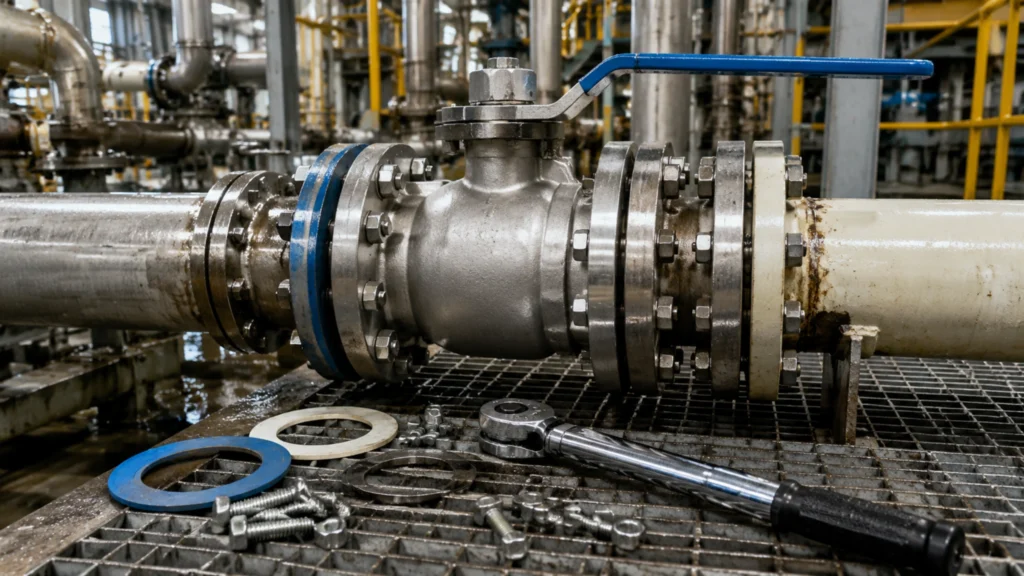
A contractor once called me from a site in Saudi Arabia where they’d just received twenty-four 10-inch Class 600 flanged ball valves for a gas processing plant. The valves were installed, the flanges were torqued, and the system was pressurized to 800 psi for hydro testing. Within two hours, six flange joints were weeping. Not leaking catastrophically. Just a slow weep – maybe a drop every ten seconds at each joint. But six joints out of forty-eight is a 12.5% failure rate on a brand new installation. The contractor was convinced the gaskets were defective. They weren’t. The flange facing on the valves was a smooth finish, Ra 1.6 microns, which is standard for spiral-wound gaskets. But the mating pipe flanges had been in storage for two years and had light surface rust that the crew had wire-brushed before installation, leaving a surface finish closer to Ra 12. The spiral-wound gaskets couldn’t fill the roughness on the pipe flange side, and gas was finding its way through the microscopic gaps. The fix was to remove all forty-eight gaskets, dress the pipe flange faces with a flange facing machine to bring them back to Ra 3.2-6.3, and install new gaskets. Cost: about $28,000 in labor and materials for a problem that would have been caught by checking the flange face finish during installation. Flanged ball valves account for about 70% of all industrial ball valve installations. The flange connection seems simple – two flat faces, a gasket, some bolts. But getting it right involves a chain of decisions about flange type, facing finish, gasket material, bolting grade, and torque procedure. When any link in that chain is wrong, the flange leaks. Here’s what actually matters. Flange types and when to use each one Raised face (RF) flanges are the standard for Class 150 through 600. The raised face is a circular boss on the flange face, typically 1.6 mm high, that concentrates the bolt load on a smaller gasket area. This increases the gasket seating stress for a given bolt load, which improves the seal. RF flanges with spiral-wound gaskets will handle the vast majority of industrial applications without issues. Flanged ball valves with RF facing are stocked by every manufacturer in sizes from NPS 1/2 to NPS 48 across Class 150 through 600. Raised face height matters – ASME B16.5 specifies 1.6 mm for Class 150 and 300, and 6.4 mm for Class 400 and above. If too short, the gasket doesn’t get enough compression because the flange bolts bottom out. If too tall, the gasket over-compresses and the metal winding crushes. I once measured a batch of Class 300 flanged valves where the raised face height was 1.1 mm instead of 1.6 mm. The gaskets couldn’t seal at full rated pressure because the bolt load wasn’t transferring to the gasket. The valves all had to be re-machined. Flat face (FF) flanges exist for connecting to cast iron equipment. Cast iron flanges will crack if you bolt them to a raised face flange because the raised face concentrates the bolt load on a small area of brittle cast iron. The rule is simple: never bolt a raised face flange to a flat face flange, and never bolt a raised face flange to cast iron equipment. If your valve has raised face flanges and your mating equipment is cast iron, you either machine the raised face off the valve flange or you install a flat face adapter spool between them. Ring type joint (RTJ) flanges are the standard for Class 900 and above. An RTJ flange has a machined groove in the flange face that accepts a metal ring gasket. When the bolts are tightened, the ring deforms plastically into the groove, creating a metal-to-metal seal that’s far more reliable at high pressure than any soft gasket. The ring is a consumable – every time you break the flange, you replace the ring. Maintenance cost roughly doubles compared to RF flanges, but at 2,200 psi on a Class 900 gas line, the alternative is a gasket blowout that nobody wants to be near. RTJ rings come in three types: Type R oval rings – the original design, self-centering, can be installed in either orientation. Type R octagonal rings – higher seating stress, seal slightly better, but must be installed with the correct orientation. Type RX rings – pressure-energized (internal pressure increases seal contact force), used for Class 900 and above in gas service. Type BX rings – for Class 5000 and above, rarely seen outside wellhead equipment. API 6D flange specifications typically call for RTJ flanges at Class 900 and above for gas service. The RTJ groove is the precision part. ASME B16.20 specifies a groove surface finish of Ra 3.2 microns maximum, with a tolerance of ±0.05 mm on the groove width and depth. If the groove is too wide, the ring doesn’t seat. If it’s too narrow, the ring bottoms out in the groove before the flange faces make contact. I’ve seen RTJ flanges where the groove had been machined with a worn tool and the surface finish was closer to Ra 12. The rough surface cut into the ring during assembly, creating a leak path that was invisible after installation and only showed up when the line was pressurized. Flange type quick reference Flange type Pressure class Key feature Common gasket Raised Face (RF) Class 150 – 600 1.6 mm or 6.4 mm raised boss Spiral-wound Flat Face (FF) All classes (for cast iron) No raised boss; full face contact Full-face gasket Ring Type Joint (RTJ) Class 900 and above Machined groove for metal ring Metal ring (oval, octagonal, RX, BX) Gasket selection: the decision that makes or breaks the joint The gasket doesn’t just fill the gap between the flanges. It has to maintain a seal while the flanges move relative to each other – from thermal expansion, from pipe support settlement, from pressure fluctuations that stretch the bolting. The gasket material, type, and thickness all
What Is a Casting Ball Valve 丨 How Castings Are Made, Inspected, and When They Are the Right Choice
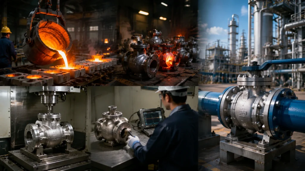
A valve distributor once sent me photos of a 12-inch Class 600 ball valve body that had cracked during a hydrostatic test at 2,220 psi. The body was a WCB carbon steel casting. When we sectioned it, the fracture surface showed a shrinkage cavity about 8mm in diameter, roughly 15mm below the inner surface of the body wall, right at the transition from the flange to the body barrel. The cavity had been there since the casting cooled in the foundry. It had survived machining because it was below the machined surface. It had survived the manufacturer’s hydro test at 1.5 times rated pressure because the remaining wall thickness at the cavity was still enough to hold 3,330 psi without failing. But it reduced the effective wall thickness by about 30% at that location, and when the valve went into service on a gas line operating at 1,400 psi with pressure pulsations from a reciprocating compressor, the stress concentration at the cavity initiated a fatigue crack that propagated through the wall in about 4,000 operating hours. The casting had passed every inspection it received because none of those inspections were looking for internal defects below the machined surface. The foundry that poured it didn’t radiograph the casting. The manufacturer didn’t ultrasonically inspect it. The buyer accepted the mill certificate and the hydro test report. The cavity was invisible to all of them. Cast ball valves are the most common body construction for industrial ball valves below Class 600, and when they’re made right and inspected properly, they perform every bit as well as forgings for their intended service. The problem is that “made right and inspected properly” doesn’t happen automatically. It requires a foundry that controls its process, a manufacturer that verifies the casting quality with NDE, and a buyer who understands what inspection results to ask for. Here’s what you need to know about cast ball valves, what can go wrong, and how to make sure it doesn’t go wrong on your order. What casting is and why it dominates below Class 600 Casting is the process of pouring molten metal into a mold and letting it solidify. The mold contains a cavity in the shape of the valve body, formed by a pattern that’s removed before pouring. The metal flows into the mold, fills the cavity, and cools from the outside in. The cooling rate varies with the section thickness – thin sections like the body barrel cool quickly, thick sections like the flange cool slowly – and the grain structure varies accordingly. Fast cooling produces fine grains. Slow cooling produces coarse grains. The transition between thick and thin sections is where stress concentrates and where casting defects are most likely to form. The standard material for cast ball valve bodies is ASTM A216 Grade WCB, a carbon steel with a maximum carbon content of 0.30%, tensile strength of 485-655 MPa, and yield strength of 250 MPa minimum. WCB accounts for about 65% of all industrial ball valve bodies globally. It’s rated for -29C to 425C and handles the vast majority of oil and gas, chemical, and power generation applications. For low-temperature service, A352 LC3 or LCC is used, rated to -46C and -196C respectively. For corrosive service, A351 CF8M 316 stainless is the standard cast grade. Cast ball valves in WCB carbon steel are the workhorse of industrial piping up to Class 600 and NPS 24. Casting is cheaper than forging because the mold is reusable for standard sizes, the process doesn’t require a forging press, and the as-cast shape is close to the finished dimensions, which reduces machining time. The cost advantage is 25-40% compared to a forged body of the same size and class. For utility and secondary process valves where the service conditions are moderate, that cost difference adds up to significant project savings without compromising performance. What can go wrong in a casting Casting defects fall into a few categories, and knowing what they are helps you understand which inspection methods catch them. Shrinkage porosity – happens when the metal shrinks as it solidifies and the shrinkage isn’t fed by additional molten metal from a riser. The result is a network of small voids, typically in the thickest sections of the casting where the solidification is slowest. Shrinkage is invisible from the surface and can only be detected by radiography or ultrasonic inspection. Isolated shrinkage porosity below about 2% of the wall cross-section is generally acceptable. Connected porosity that creates a leak path through the wall is not. The foundry controls shrinkage through proper gating and risering design, pouring temperature control, and directional solidification techniques that ensure the thick sections are the last to freeze and are fed from risers during solidification. Gas porosity – caused by gases dissolved in the molten metal coming out of solution during solidification. The result is small, spherical voids distributed through the casting. Hydrogen porosity in steel castings appears as small, shiny cavities on a fracture surface. Gas porosity is controlled by proper deoxidation of the melt and by controlling the moisture content of the mold and the pouring environment. Inclusions – non-metallic particles trapped in the metal – slag from the furnace, sand from the mold, or deoxidation products that didn’t float to the surface of the melt. Inclusions act as stress concentrators and can initiate fatigue cracks. The foundry controls inclusions through proper slag removal, clean pouring practices, and ceramic filters in the gating system that trap particles before they enter the mold cavity. Hot tears – cracks that form during solidification when the casting is still hot and the metal has low ductility, but thermal contraction is pulling it apart. Hot tears typically form at section transitions where the cooling rate varies and one section contracts faster than the adjacent section. They’re visible on the surface and can be detected by visual inspection, magnetic particle, or liquid penetrant testing. Cast vs forged valve body defects include all of these categories, and the inspection
How to Choose an Industrial Ball Valve 丨 What Actually Matters and What Nobody Tells You
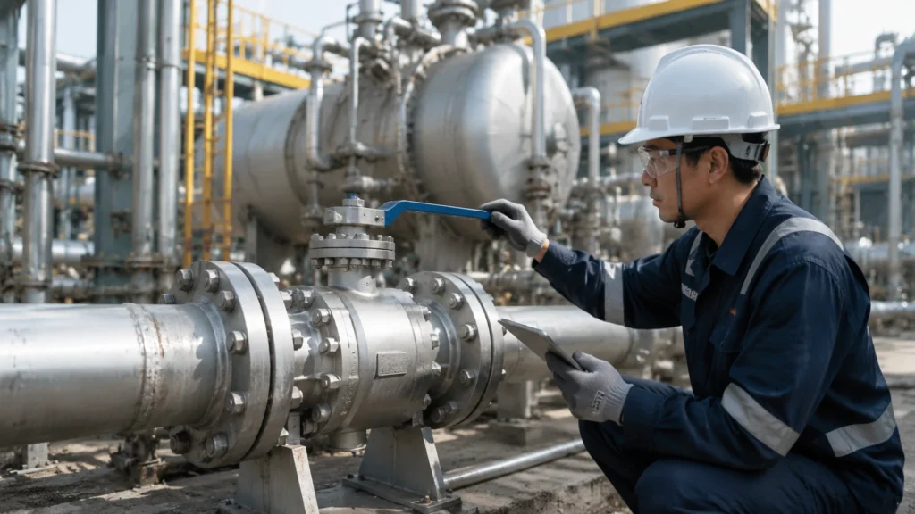
About eight years ago, a procurement manager at a refinery in Southeast Asia called me in a panic. They’d ordered twenty-four 8-inch Class 300 ball valves for a crude oil transfer line. The valves arrived on site, passed visual inspection, got bolted in, and the system was pressurized to 600 psi. Within 48 hours, three valves were leaking through the stem packing. By the end of the week, seven had seat leakage above the API 598 allowance of 10 mL/min per inch of nominal diameter. Total repair cost: 60,000 dollars. Lost production: 11 days. Root cause: the valves had PTFE seats rated only to 180C, but the crude was running at 195C on startup. Nobody had checked the actual seat material temperature rating against the process conditions. The datasheet said “PTFE” and the buyer assumed that meant “good enough.” It wasn’t. Industrial ball valves look simple. A sphere with a hole in it, rotated 90 degrees. Open. Closed. What could go wrong? The answer, I learned over years of seeing these things fail in the field, is: pretty much everything. Material mismatch, wrong pressure class, improper installation, operating the valve as a throttle when it was never designed for it. Most failures aren’t manufacturing defects. They’re selection mistakes made months before the valve ever arrived on site. This is what I wish someone had handed me when I started specifying ball valves for industrial applications. No theory. No marketing-speak. Just what breaks, why it breaks, and how to not be the person who bought the wrong valve. If you need a quick reference for what you’re buying, API 6D ball valve specifications cover the core pressure and material data points you’ll need upfront. But if you want to understand the decisions that actually determine whether your valve lasts six months or fifteen years, keep reading. The two valve architectures that matter (forget everything else) Industrial ball valves come in hundreds of configurations, but for the purposes of not getting it wrong, there are really two architectures you need to understand: floating ball and trunnion mounted. Everything else is a variation. Floating ball valve – holds the ball between two seats with no lower support. The ball floats downstream under pressure, pressing against the downstream seat to create the seal. This works fine up to about 6 inches nominal bore and Class 600. Past that, the physics turn against you fast. At 10 MPa line pressure on an 8-inch valve, the ball exerts roughly 1,800 Nm of torque on the stem. That’s more than most manual operators can overcome without a cheater bar, and if someone grabs a cheater bar, you get a twisted stem and a valve that’s permanently jammed. Trunnion mounted ball valve – fixes the ball with upper and lower bearings (trunnions) so the ball doesn’t move under pressure. The seats are spring-loaded and press against the ball instead. This design scales up to 60 inches and Class 2500 without the torque problems. Operating torque at 10 MPa drops from over 1,800 Nm to under 650 Nm. Seat replacement cycles extend from about 8 months to over 60 months. If your application is above 6 inches or above Class 600, you’re in trunnion territory. There’s no debate about this. API 6D trunnion mounted ball valves are the standard for oil and gas pipelines above Class 600 for exactly this reason. Port type is the other decision people get wrong. Full bore – the ball opening matches the pipe ID. No restriction. You can send a pig through it. Reduced bore – the ball opening is one pipe size smaller than the connection. Cheaper, lighter, but you get a pressure drop and can’t pig the line. For crude oil, natural gas, and any line that needs pigging, full bore is non-negotiable. For water, low-pressure chemical transfer, and applications where pressure drop doesn’t matter, reduced bore saves money. Just don’t use it on a line that someone might want to pig later. I’ve seen that decision cost a plant a two-week shutdown because they couldn’t clean the line without cutting it open. Full bore forged ball valves exist specifically because this mistake gets made so often. Material decisions that separate the five-year valve from the twenty-year valve Body material is the easy part. Carbon steel ASTM A105 for most applications. Low-temp carbon steel LF2 if you’re below -29C. 316L stainless for chemical plants and anything corrosive. Duplex stainless F51 or super duplex F53 when you have chlorides and need higher strength. Inconel 625 or Hastelloy C276 for the really nasty stuff – sour gas, hydrofluoric acid, deep subsea. Nobody gets the body material wrong because it’s on every datasheet. The decision that actually determines service life is the seat material. And this is where I’ve watched more valves fail prematurely than anywhere else. Seat Material Key Properties Limitations / Gotchas PTFE Cheap, chemically inert, seals beautifully at room temperature. Thermal expansion coefficient ~10x that of carbon steel. At 85C in a 6-inch valve, can protrude 0.45mm into the ball path. Cycle through desert temp swings (85C day / 10C night) 30 times → seat compression force drops 65%. Above 200C starts cold-flowing; by 260C structurally gone. The soft seated vs metal seated decision comes down to: if your temperature ever exceeds 200C, you don’t have a choice. PEEK Useable to 260C. Compressive strength 8,500 psi at 100C (vs 900 psi for pure PTFE). Send 300C superheated steam through during line cleaning → surface crystallizes and fractures within five minutes. PEEK shards go downstream and jam flow meters. Fix: if you steam-clean, you need metal seats. Metal Seated (tungsten carbide coatings, Stellite 6 overlays, chromium carbide) Operate at 500C, survive abrasive slurries at 25 m/s, last decades if maintained. Tungsten carbide coated ball with HVOF application at 800 m/s gives 0.2mm thick coating, HRC 70 hardness, porosity <1%. In silica sand slurry at 25 m/s, annual wear <0.01mm after 12 months. Won’t provide bubble-tight shutoff in most cases – expect
How to Choose a Ball Valve Manufacturer 丨 What Separates the Good Ones From the Ones That Cost You Six Figures
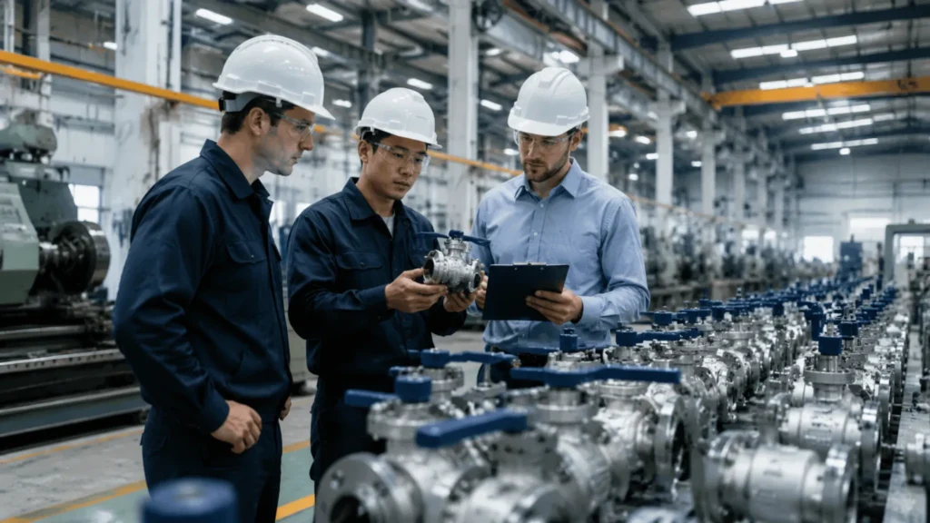
About six years ago, a procurement director at an EPC firm in Dubai showed me two ball valve quotes for a gas processing project. Both valves were API 6D certified, Class 600, 12‑inch, A105 forged body, PEEK seats. One manufacturer quoted $4,200 per valve. The other quoted $2,850. The procurement guy was leaning toward the cheaper one because “they have the same certifications on paper.” I told him to fly to both factories before signing. He didn’t. Sixteen months later, three of those valves had seat leakage above API 598 limits. One had stem packing that was leaking process gas at about 18 mL per minute. The cost to replace the seats and repack the stems across the entire order was $47,000 in parts and labor. The production downtime was seven days at roughly $180,000 per day. The cheap valves cost $1.3 million more than the expensive ones would have. This happens all the time. Two manufacturers claim the same certifications. The datasheets look identical. The pricing spread is 30 to 40 percent. And the decision gets made on price because nobody knows what else to look at. I’ve spent years auditing valve factories across China, India, and Southeast Asia, and I can tell you: the difference between a good ball valve manufacturer and a bad one isn’t visible on the quotation. It’s in the melt shop, the testing bay, and the way they handle problems after the invoice is paid. This is what I wish every buyer had before they cut their first purchase order. The certifications aren’t what you think they are Every manufacturer’s website lists API 6D, API 608, ISO 9001, CE marking. The logos are at the bottom of every page. Buyers assume this means quality is guaranteed. It doesn’t. An ISO 9001 certificate means the manufacturer has a documented quality management system. It does not mean they follow it on every order. It does not mean they apply the same quality control rigor to export orders as they do to domestic ones. It doesn’t even mean they’re using the same material grades they list on the certificate. I once watched a supplier use A105 carbon steel castings that were supposed to be WCB. The casting foundry had substituted the material because WCB was on backorder and A105 was available from stock. The chemical composition was close enough that a visual inspection would never catch it. But A105 is a forging grade, not a casting grade. The grain structure is completely different. Under cyclic pressure loading, cast A105 has about 40% lower fatigue life than proper WCB. The substitution wasn’t caught until a third‑party lab did PMI testing on a random sample from the batch. By then, twelve valves were already installed on a live pipeline in Qatar. Real certification means API certified manufacturers who provide full EN 10204 3.1 material traceability. Not Type 2.1 self‑declarations. Type 3.1 means an independent inspector witnessed the chemical analysis and mechanical testing. Every heat number is traceable to the original mill certificate. Every pressure‑containing component has a paper trail. For sour service, you want PMI on every heat, not a sample, and the XRF gun reading should deviate from the mill cert by less than 0.1% on critical elements like chromium, molybdenum, and nickel. Fire‑safe certification is another one buyers misunderstand. A manufacturer claiming “API 607 fire‑safe design” doesn’t mean they’ve actually fire‑tested your valve model. It means they have a certificate for a valve of similar design that passed the test. If your valve size, pressure class, or seat material differs from what was tested, the fire‑safe claim is an extrapolation, not a certification. The only way to be sure is to ask for the specific API 607 test report that matches your valve’s exact configuration: same size, same pressure class, same seat material, same body material. If they can’t produce it within 48 hours, they don’t have it. Material traceability is the difference between a five‑year valve and a five‑minute disaster The single most important thing that separates a serious API 6D ball valve manufacturer from a price‑driven supplier is what happens in the melt shop. I’ve spent more time than I want to think about standing in foundries watching molten steel get poured, and here’s what I’ve learned: if the manufacturer can’t tell you the exact chemical composition of the steel in your valve body, down to the parts‑per‑thousand level, you’re gambling. A proper foundry takes a sample from every heat. The steel is brought to 1,550°C, a ladle sample is poured into a chill mold, and a spectrometer analyzes it within minutes. Carbon content above 0.30% on a WCB casting? The heat gets adjusted or scrapped. Nickel below 10.0% on 316 stainless (CF8M)? Same thing. Molybdenum below 2.0% on duplex? Rejected. The sample slug gets stamped with the heat number and archived for three years minimum. Every valve body cast from that heat carries the same number, traceable all the way back to that spectrometer reading. When this system breaks down, you get the kind of failures that make incident reports. A 12‑inch Class 900 valve on a sour gas line in the Middle East failed catastrophically in 2019 because the body material was supposed to be NACE MR0175‑compliant WCB with hardness below HRC 22, but the actual casting measured HRC 28 at three points. The foundry had added scrap steel to the melt to reduce cost, introducing residual chromium that increased hardenability. The harder steel cracked under sulfide stress within eight months of commissioning. The valve body split along a casting inclusion that was visible on the fracture surface with the naked eye. Root cause: no spectrometer verification of the heat chemistry, no PMI on the finished casting, and no independent inspector on site. For sour service, the HRC 22 limit in NACE MR0175 is not a suggestion. It’s a hard limit derived from decades of failure data showing that carbon steel above this hardness will crack when exposed to wet H₂S. If
How Forged Ball Valves Are Made 丨 The Forging Process, Material Grades, and Inspection That Guarantee Quality
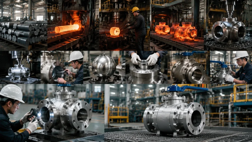
An engineer at a gas processing facility in Qatar once showed me the mill certificate for a batch of A105 forged valve bodies. The certificate listed the correct chemistry, the correct tensile strength, the correct heat number. Everything matched the purchase order. But when I picked up one of the valve bodies and looked at the surface finish, something felt wrong. The forging had the uniform, slightly rough surface texture of a properly forged part, but the radius at the flange-to-body transition was too sharp – maybe 3 mm where the drawing called for 8 mm. A sharp radius in a forging is a stress concentration. At 2,200 psi operating pressure with thermal cycles from ambient to 200 °C, a sharp radius can initiate a fatigue crack within a few thousand cycles. We ultrasonic tested the radius and found no cracks yet. But we rejected the entire batch of sixteen valves because the forging geometry didn’t match the drawing, and a forging with the wrong geometry is no better than a casting with the wrong wall thickness. The supplier had used a worn die that no longer produced the specified radius, and their quality control didn’t catch it because nobody was checking the forging dimensions against the drawing before machining. The dies had made about 800 forgings since the radius last met specification. Every one of those valves is a potential fatigue failure waiting to happen. A forging is only as good as the die that shapes it, the heat treatment that follows, and the inspection that verifies the result. A forged ball valve gets its strength from the forging process itself. The steel is heated to about 1,150 °C and mechanically worked under thousands of tons of pressure, aligning the grain structure along the stress paths the valve will see in service. Here’s what goes into a properly forged valve body, the standards that govern the process, and how to tell a good forging from a bad one. The forging process: heat, pressure, and grain flow Steel for a forged valve body starts as an ingot or a continuously cast billet from the steel mill. The mill certificate documents the heat chemistry – carbon, manganese, silicon, phosphorus, sulfur, chromium, nickel, molybdenum, and any other specified elements. For A105 carbon steel, the key limits are: Carbon: 0.35 % maximum Manganese: 0.60–1.05 % Silicon: 0.15–0.35 % Phosphorus: 0.035 % maximum Sulfur: 0.040 % maximum These limits are tighter than the equivalent casting grade WCB, which is one reason forgings have more consistent mechanical properties than castings. The billet is heated in a furnace to the forging temperature, typically 1,100 °C to 1,250 °C for carbon steel. The temperature has to be uniform throughout the billet. If the center is cooler than the surface, the forging won’t flow uniformly, and the grain structure will vary through the section. The billet is transferred to the forging press, where it’s positioned in a die that has the negative shape of the valve body machined into it. The press applies force – for a 12‑inch Class 600 valve body, roughly 5,000 to 8,000 tons of press force – and the steel flows into the die cavity. The forging ratio is the critical parameter that determines whether the part has true forging properties or behaves more like a casting. The ratio is the cross‑sectional area of the original billet divided by the cross‑sectional area of the thickest section of the finished forging. API and ASTM standards require a minimum forging ratio of 3:1 for pressure‑containing components. This means the original billet had at least three times the cross‑section of the finished part, and the forging process reduced it to one‑third of that area through mechanical working. Below 3:1, the grain structure isn’t sufficiently refined, and the mechanical properties approach those of a casting rather than a forging. A 12‑inch Class 600 valve body with a main body diameter of about 18 inches has a cross‑sectional area of roughly 250 square inches. To achieve a 3:1 forging ratio, the starting billet needs a cross‑section of about 750 square inches – roughly a 31‑inch diameter cylinder. The forging press has to reduce that 31‑inch billet to the 18‑inch body shape, which requires enough press force to flow the steel into the die cavity at the forging temperature. This is why larger valves need larger forging presses, and why the maximum size of a forged valve body is limited by the available press capacity. Industrial forged ball valve manufacturers with access to large forging presses can produce bodies up to NPS 24, and in some cases NPS 30 for specialized applications. Heat treatment: what happens after the forging press The forging process leaves the steel in a stressed condition. The mechanical working has deformed the grain structure, but the rapid cooling after forging – even in still air – creates internal stresses and a mixed microstructure that’s not optimal for service. Heat treatment relieves the stresses and produces the desired microstructure and mechanical properties. Normalizing is the standard heat treatment for A105 forged carbon steel valve bodies. The forging is heated to about 900 °C, held at temperature long enough for the microstructure to fully transform to austenite – typically one hour per inch of section thickness – and then cooled in still air. Normalizing refines the grain size, improves the uniformity of the microstructure, and produces the tensile and yield strength specified in the material standard. The cooling rate determines the final grain size. Faster cooling produces finer grains and higher strength. Slower cooling produces coarser grains and higher ductility. Quenching and tempering provides higher strength than normalizing. The forging is heated to the austenitizing temperature, then quenched in water, oil, or polymer solution to produce a hard martensitic structure. The quenched forging is brittle and highly stressed, so it’s immediately tempered – reheated to 550 °C to 700 °C – to reduce the hardness and improve the toughness while retaining most of the strength increase from quenching. Quenched and tempered A105 can achieve yield strengths above 300 MPa compared to 250 MPa for normalized material, which allows thinner walls for
How to Design a Valve Specification Sheet for Oil Refinery EPC Projects | Data Sheet Fields Explained
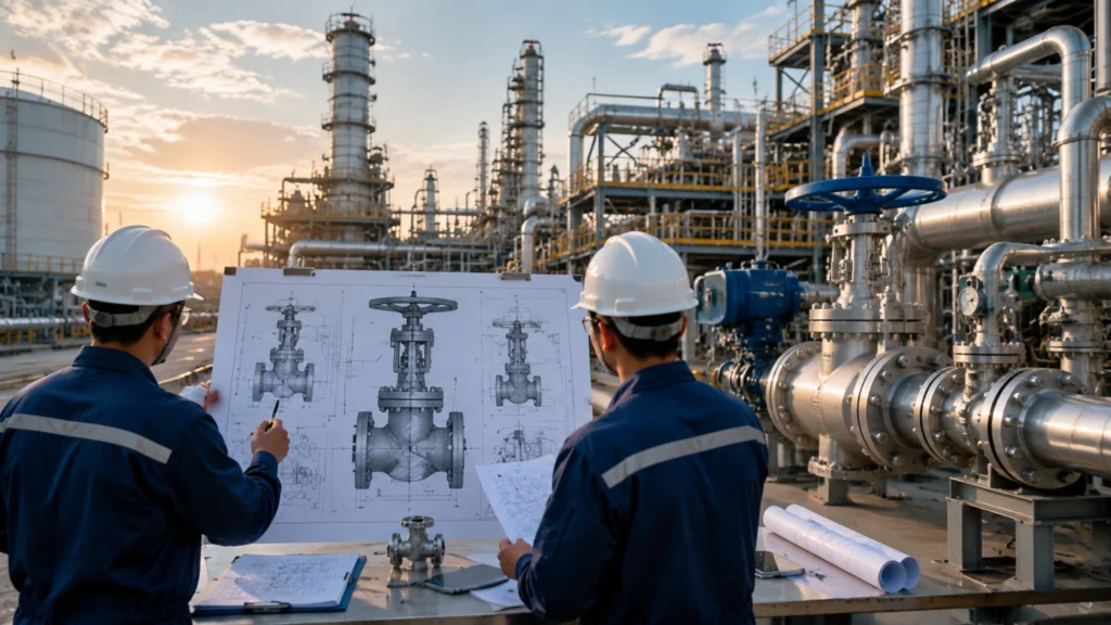
In petrochemical EPC projects, the valve data sheet serves as the critical technical bridge linking design, procurement, and construction. A complete data sheet must cover four major sections: project information, process parameters, valve body parameters, and special requirements. Any omission or error in these fields will propagate into procurement documents, leading to irreparable rework losses at the construction site. Data Sheet Fundamentals How to Fill in Project Information In EPC projects, the project information section at the top of the data sheet is often filled out in haste, yet it directly impacts the legal validity of subsequent procurement and construction contracts. Data Sheet (DS) Number: The unique identifier for the document. Project Code: Must match the official contract version. Unit Code: E.g., “RF-01” for an atmospheric distillation unit. Contract Number: Ties the equipment to the legal procurement scope. Design institutes should use the official full project name as stated in the contract, avoiding any abbreviations to prevent documentation mismatches during owner handover. Where Process Parameters Come From Process parameters in a valve data sheet are not arbitrary; they are derived from P&IDs (Piping and Instrumentation Diagrams) and process design specifications. Design Pressure & Temperature: Taken from piping design conditions; must account for hydrostatic test pressure requirements per API 521[1] or ASME B31.3. MAWP (Maximum Allowable Working Pressure): Must be the controlling parameter during selection as it may exceed design pressure due to temperature compensation. Operational Boundaries: Must specify normal operating ranges, abnormal boundary conditions, and emergency shutdown requirements. For example, in cryogenic service (-196°C), valve body materials must be upgraded from WCB to LCA or LCB to prevent brittle fracture. Pipeline and Instrument Tagging The Line Number and Instrument Tag are the vital links between the data sheet and the P&ID. Mismatches here lead to massive site rework. Standard Pipeline Numbering: “Piping Class – Nominal Diameter – Material Class” (e.g., L1B-8-SS316). Instrument Tags: Follow ISA S5.1[2] (e.g., TV for Control Valves, FV for Flow Control Valves). Valve Parameters Parameter Category Key Considerations Size (DN/NPS) Must use a unified standard; conversion is not linear (e.g., DN25 is 1″, but DN80 is 3″). Pressure Rating Must match system MAWP; verify using ASME B16.34 temperature correction factors. Material Must specify body, bonnet, stem, seat, and ball/plug materials based on NACE/ISO requirements. Size and Pressure Rating Valve size is the primary selection parameter. Calculation is based on maximum design flow, allowable pressure drop, and fluid characteristics. The actuator must be sized to overcome both pipeline thrust and internal sealing friction. Always ensure the pressure rating is compatible with the system; a Class 150 valve cannot be used in a Class 600 system. Material Requirements Material selection is your main defense against corrosion. Always specify the material for all wetted parts, not just the body. Carbon Steel (WCB/WCC): For non-corrosive hydrocarbons (-29°C to 425°C). Alloy Steel (LCB/LCC, WC6/WC9): For sour or cryogenic conditions. Stainless Steel (CF8M/CF3M): For corrosive media and low-temperature environments. For sour service, ensure compliance with NACE MR0175[3]/ISO 15156. Specify the exact grade (e.g., CF8M) rather than a generic term like “stainless steel” to avoid catastrophic failures. End Connections End connections define installation space and mounting method: Flanged (ASME B16.5): Specify face type (RF, RTJ, or FF). Butt-weld (BW): Used for high-pressure/high-temp; specify welding bevel (ASME B16.25). Socket-weld (SW) & Threaded (NPT): Suitable for small-bore valves, typically up to Class 2500. Special Requirements NACE Compliance NACE MR0175/ISO 15156[5] is mandatory for sour oil and gas fields. Trigger point: If $H_2S$ partial pressure exceeds 0.001 bara, NACE compliance is required. Valves must be manufactured using controlled steel smelting (sulfur < 0.02%) and verified Carbon Equivalent (CE) levels. Missing NACE documentation is a common cause for project delivery delays. Fire-Safe Requirements Fire-Safe valves ensure sealing and operability during a fire. Standards API 607 and API 6FA[6] require the valve to withstand 1093°C for 30 minutes. Always verify the certification number on the official API website to avoid counterfeit certificates. Third-Party Inspection (TPI) TPI is the final quality gate. Specify the inspection level in the data sheet: Level I: High-stringency; includes 100% UT and RT testing. Level II: Standard; 10% sampling of tests. Level III: Basic; visual and dimensional checks only. Ensure all materials provide valid EN 10204[7] 3.1 certificates with matching heat batch numbers. Quality control begins at the design source. Before issuance, ensure a joint sign-off by process, piping, procurement, and quality departments to prevent costly site rework.
How to Select Valve Materials for Chemical Plant Pipelines | Corrosion Resistance Guide for Acids and Alkalis
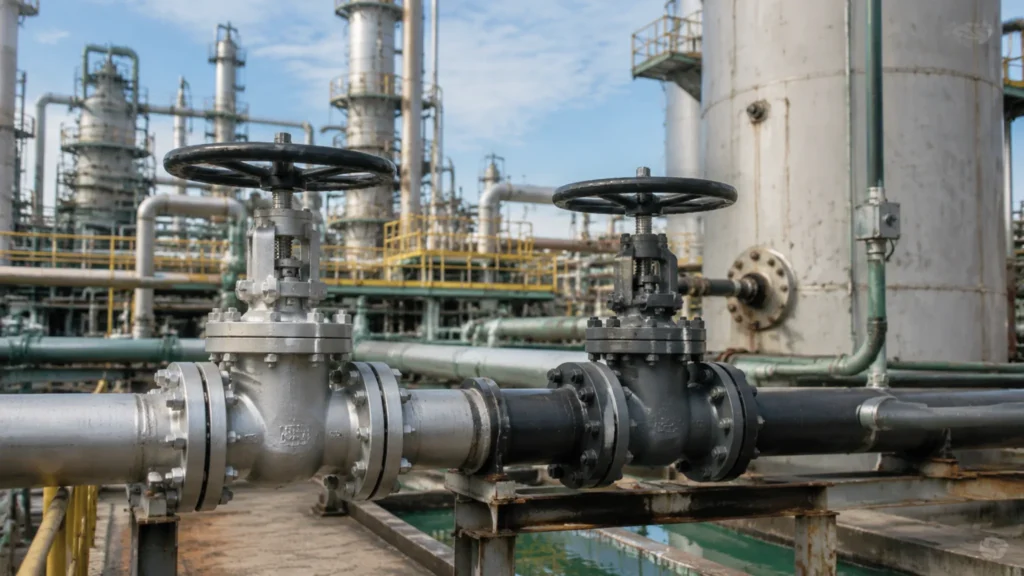
Valve material selection for chemical plant pipelines requires matching corrosion mechanisms with appropriate alloys. The survival of a material depends on acid type, concentration, temperature, and chloride content. Common Corrosive Media What Materials Handle Sulfuric Acid Corrosion engineers frequently encounter the ‘concentration reversal’ phenomenon in sulfuric acid service. What works at low concentration can fail at high concentration, and vice versa. The H₂SO₄ reducing/oxidizing curve divides the concentration‑temperature map into two zones. Below approximately 62% concentration, H₂SO₄ behaves as a reducing acid — stainless steel and carbon steel both corrode at rates dependent on temperature and alloy content. Above approximately 62%, H₂SO₄ becomes oxidizing. Carbon steel passivates, dramatically reducing its corrosion rate. A sulfuric acid transfer line at a refinery operated for over 15 years with carbon steel pipe in 95% H₂SO₄ at 60°C. The same design would fail catastrophically in 20% H₂SO₄ at the same temperature within 2 years. The relevant standard for H₂SO₄ material selection is ASME B16.34 Appendix F, which provides reference corrosion rate data across the H₂SO₄ concentration spectrum. Always locate your operating concentration on the iso‑corrosion chart before selecting materials. Sulfuric acid is the most common corrosive medium in chemical plant pipelines. Yet concentration and temperature shifts can completely reverse the material selection verdict. For H₂SO₄ below 10% concentration, austenitic stainless steels such as 304 perform acceptably below 40°C — but above that threshold, 304 develops pitting corrosion. At concentrations above 50%, sulfuric acid becomes strongly oxidizing. Carbon steel paradoxically forms a protective FeSO₄ film, reducing corrosion rates to below 0.1 mm/year. In a Xinjiang potassium sulfate plant, the design institute specified 316L for 70% sulfuric acid at 80°C, assuming ‘stainless steel is safer’. Three years later, the valve body wall thickness was below minimum required after 316L corroded at 1.2 mm/year, while WCB carbon steel would have corroded at only 0.05 mm/year under identical conditions. Concentration Temperature Material Corrosion Rate (mm/year) 10%–60% above 60°C 316L or above varies above 50% above 80°C carbon steel or ductile iron < 0.1 PTFE soft seals are unsuitable for high‑temperature sulfuric acid — at 50°C with 65% H₂SO₄, PTFE seats become brittle within 6 months. The four critical variables for sulfuric acid valve selection are concentration, temperature, flow velocity, and oxygen content. Intermittent operation creates low‑point accumulations of dilute acid. This caused a 304 butterfly valve to perforate after 2 years in a nitric acid/phosphate fertilizer plant. Adding an automatic spray cleaning system at dead‑legs solved the problem. Key field data: 20% dilute sulfuric acid at 50°C: 316L corrosion rate approximately 0.3–0.5 mm/year 70% sulfuric acid at 80°C: WCB carbon steel rate approximately 0.05 mm/year; 316L reaches 1.2 mm/year This reversal — carbon steel outperforming stainless steel at high concentration — is counterintuitive but validated by corrosion handbooks and plant operating records. For H₂SO₄ above 85%, carbon steel is the only economical choice. Even Hastelloy C‑276 offers no advantage over carbon steel at high concentration and temperature. Special Requirements for Hydrochloric Acid and HF In hydrochloric acid service, trace levels of oxidizing agents — nitric acid, ferric chloride (FeCl₃), or dissolved oxygen — dramatically change the corrosion electrochemistry. A chemical plant producing phosphoric acid via the wet process extracted HCl from rock digestion effluent. Trace Fe³⁺ ions from phosphate rock accelerated 316L corrosion by approximately 5x compared to reagent‑grade HCl of equivalent concentration and temperature. Always request a full media analysis from the process licensor, including trace metal ion content and dissolved gases, before finalizing material selection for HCl service. HF service adds another layer of complexity: HF is both a poison and a reactant in many analytical methods, making media purity analysis difficult. A common field problem is HF containing trace silica (SiO₂) from the production process. Even 10–20 ppm SiO₂ in HF significantly changes its reactivity with silicon‑containing alloys, invalidating laboratory corrosion test data obtained with high‑purity HF reagents. Hydrochloric acid (HCl) and hydrofluoric acid (HF) are the two most demanding corrosive media in chemical plant service. HF requires completely different selection logic. For HCl, 316L is marginally acceptable below 20% concentration at room temperature, with corrosion rates of 0.1–0.3 mm/year. But above 60°C, even 5% HCl causes general corrosion on 316L. A fluorosalt production line using 316L valves for 15% HCl at 50°C perforated within 6 months. Hastelloy C‑276 has operated without issue ever since, though it costs 8–15 times more than 316L. HF acid dissolves protective fluoride films on metal surfaces, making even noble metals vulnerable. PTFE or PVDF‑lined valves are required for ambient temperature, low‑concentration HF (below 10%). But lining integrity is critical: a semiconductor‑grade chemical factory found PTFE‑lined ball valves delaminating from the valve body after 8 months in 20°C, 40% HF service. Only all‑metal PFA/PVDF diaphragm valves have provided stable service in this application. Material selection for HCl and HF is not a single‑variable problem. Temperature is the decisive factor in HCl service — for every 20°C increase in temperature, 316L’s corrosion rate in HCl approximately doubles. In HF service, material purity of the acid becomes critical: trace SiO₂ impurities in hydrochloric acid react violently with magnesium‑bearing alloys. HF also penetrates skin and binds with bone calcium, causing systemic toxicity — valve failure in HF service directly threatens personnel safety, not just plant operation. Monel 400 (67% Ni‑Cu alloy) offers the best cost‑performance ratio for low‑concentration HF. It has operated safely for over 6 years in a fluorite flotation plant handling 15% HF at 50°C. For HF above 60% concentration or above 80°C, only platinum or tantalum can cope. Graphite‑impregnated PTFE or all‑metal packings are mandatory in HF service. A fluoroaluminum plant suffered HF leakage through asbestos gland packing after 6 months, nearly causing a serious personnel injury. Material Selection Principles for Alkaline Solutions Beyond SCC, caustic solutions present a crystallized salt accumulation problem. Sodium carbonate (Na₂CO₃), the reaction product of NaOH with atmospheric CO₂, has a retrograde solubility curve — its solubility decreases as temperature increases. In a hot caustic pipeline that cools during shutdown, Na₂CO₃ crystallizes and deposits
