
How to Reduce Leakage Risks with the Right API 6D Ball Valve | Seat Design, Seal Material, Pressure Balance
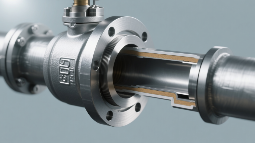
For standard operating conditions, PTFE soft-seated valves are used; for high-temperature and abrasive media, tungsten carbide metal hard seats with a hardness exceeding HRC 65 are selected. Pressure balancing requires a Single Piston Effect (SPE) design, achieving automatic pressure relief when the body cavity pressure exceeds 1.33 times the nominal value. Daily operations require regularly opening the blowdown valve to check for internal leakage; in case of sudden minor leaks, No. 790 high-pressure sealant can be urgently injected to stop the leak. Seat Design In ANSI Class 150 to 2500 applications, the Single Piston Effect (SPE) seat utilizes pipeline differential pressure to achieve sealing, and automatically relieves pressure into the pipeline when the cavity pressure exceeds 1.33 times the pipeline design pressure. The Double Piston Effect (DPE), combined with an external relief valve, provides double isolation. It utilizes Inconel X-750 metal springs with a preload of 50-150 lbs, compensating for 0.1-0.3 mm of physical wear on the soft seal inserts within the -46°C to 200°C range. The surface roughness of the support ring’s metal contact face must be controlled within Ra 0.4 microns; paired with a 5° to 10° lip chamfer, this can reduce the leakage rate to the ISO 5208 Rate A (0 drops/minute) standard. Engineering & Specifications Engineers limit the roundness tolerance of the ball surface to within 0.015 mm, paired with a machine polishing treatment achieving a surface roughness of Ra 0.1 to 0.2 microns. The inner diameter of the seat’s metal support ring and the outer diameter of the ball must form a perfectly matching spherical geometry. Manufacturing facilities use Coordinate Measuring Machines (CMM) to inspect the physical profile of the contact band, where deviations must not exceed 0.02 mm to prevent high-pressure fluids from generating micro-jet erosion at the edges of the contact surface. The machining depth tolerance of the spring groove on the back of the metal support ring is set to ±0.05 mm. Minor depth deviations alter the compression of the metal spring, leading to initial preload errors of dozens of pounds per square inch, reducing the effectiveness of the ANSI FCI 70-2 Class VI bubble-tight seal in low-pressure conditions. Physical parameter setting standards for spring components: Compression stroke is controlled within the 10% to 15% range of the free length. Inconel X-750 material requires aging treatment at 730°C for 16 hours. The spring rate of a single coil spring is typically set to 25 to 40 N/mm. 12 to 24 independent mechanical spring pockets are evenly distributed on the back of the seat ring. In 1500 psi ANSI Class 600 pipeline systems, thermoplastic polymers like Polyether Ether Ketone (PEEK) or Devlon V-API are machined into seal inserts. When turning the inserts on a lathe, a mechanical interference allowance of 0.05 to 0.1 mm is reserved. The interference fit relies on a hydraulic press to force the polymer into the metal dovetail groove of the 316L stainless steel or carbon steel support ring. The bottom angle of the dovetail groove is machined to a 15 to 20-degree incline, utilizing the undercut bite force of the metal structure to resist the high-speed erosive peeling force of the fluid inside the pipeline. When fluid pressure rises to 80% of the pipeline’s operating pressure, soft materials like PTFE undergo microscopic elastic deformation. Engineers control the physical anti-extrusion clearance at the edge of the metal ring to under 0.1 mm to prevent high pressure from extruding the polymer into the valve cavity, which would cause material tearing and deformation. Physical layout of the emergency sealant injection system: Injection ports use standard 1/8-inch or 1/4-inch NPT pipe thread connections. An annular synthetic grease channel with a width of 2 to 3 mm is machined inside the seat ring. Internally equipped with a unidirectional stainless steel check valve with an opening pressure of 30 to 50 psi. The mechanical thrust generated by high-pressure grease guns can reach 10,000 psi to penetrate pipeline agglomeration blockages. For main natural gas pipelines containing large amounts of solid sand particles, pure soft seal inserts will develop physical scratches deeper than 0.2 mm within the first 500 hours of operation. Engineering specifications mandate transitioning to a metal-to-metal seat construction system. High-Velocity Oxygen Fuel (HVOF) technology is used to attach a tungsten carbide coating to the contact surfaces of the support ring and ball. Coating thickness is precisely controlled between 0.15 mm and 0.25 mm, porosity must be less than 1%, and the overall physical bond strength is greater than 70 MPa. The metal surface hardness after spraying reaches Vickers hardness HV 1000 to 1200. This high-hardness contact surface can cut through solid particles up to 2 mm in diameter suspended in the medium, maintaining an allowable leakage rate of less than 2 drops per minute as specified by the API 598 standard under a 2500 psi differential pressure. The static sealing barrier between the seat and body is achieved collectively by an O-ring and a graphite fire-safe ring on the back. During physical installation, the cross-sectional diameter of the fluororubber (FKM) O-ring is compressed by 15% to 20%, providing a zero-leakage airtight barrier for daily pipeline operations. Mechanical response mechanism for the API 607 Fire Test: External ambient temperature reaches 750°C with sustained open-flame combustion for 30 minutes. Polymer inserts completely melt, fail, and vaporize within the 260°C to 300°C temperature range. Springs continuously provide about 200 lbs of mechanical thrust, pushing the metal support ring towards the internal ball. The secondary machined surface on the metal ring makes contact with the ball, forming a 2 mm wide metal-to-metal emergency sealing band. In deepwater subsea pipeline applications, external hydrostatic pressure increases by approximately 1 standard atmosphere for every 10 meters of depth. The seats of API 6D subsea ball valves at a water depth of 3,000 meters must withstand an external seawater backpressure of 300 bar. Engineers altered the force area ratio on the back of the support ring. By reducing the external environmental contact area to 0.8 times the internal media contact
How to Select Materials for Custom API 6D Ball Valves | Carbon Steel, Stainless Steel, Duplex Steel
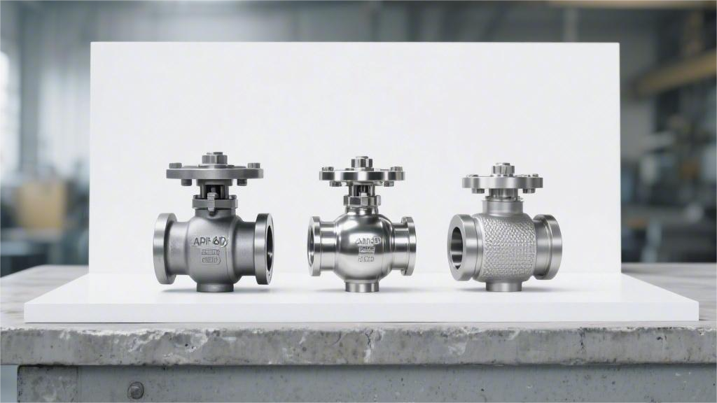
For conventional oil and gas, select carbon steel WCB, suitable for -29 to 425°C; For corrosive media, select stainless steel 316; For high-pressure sour offshore conditions, use duplex steel 2205 with a PREN value over 35 to resist pitting corrosion. Carbon Steel For operating conditions between -29°C and 425°C, ASTM A216 WCB (cast) or A105 (forged) are primarily selected, with a yield strength ≥ 250 MPa, meeting Class 150 to 2500 pressure ratings. In environments as low as -46°C, low-temperature carbon steels such as ASTM A352 LCC or A350 LF2, which have passed the Charpy V-notch impact test, must be used. Due to the relatively weak corrosion resistance of bare carbon steel, ball valve internals are often treated with a 75µm thick Electroless Nickel Plating (ENP), and in sour service conditions, the material hardness must be strictly controlled below 22 HRC to comply with the NACE MR0175 standard. Grade Applicable Temperatures In the engineering specifications for API 6D ball valves, ASTM A216 WCB is a highly prevalent cast body material. The ASME B16.34 standard explicitly sets its lower allowable working temperature limit at -29°C. When the ambient or fluid temperature remains above 425°C for prolonged periods, carbon elements within the WCB material will undergo graphitization precipitation. Under continuous high temperatures, cementite (Fe3C) in carbon steel decomposes into pure iron and free graphite, leading to a significant decline in the valve body’s mechanical strength. Engineering contractors designing high-temperature thermal oil pipelines exceeding 400°C will abandon WCB and instead require WC1 or WC6 alloy cast steels containing 0.5% molybdenum. The WCC grade, which also falls under the ASTM A216 specification, has higher upper limits for carbon content (0.25%) and manganese content (1.20%). The room-temperature tensile strength of WCC reaches the 485 MPa to 655 MPa range, which is about 35 MPa higher than WCB. In Class 600 and above high-pressure natural gas mainlines, WCC allows engineers to design pressure-bearing valve bodies with thinner walls. For API 6D ball valves smaller than 12 inches or high-pressure internals, the forged ASTM A105 is standard. The applicable temperature range for A105 is similarly restricted to -29°C to 425°C. The forging process eliminates porosity and shrinkage defects within the material, making A105’s density and grain refinement superior to WCB, and it is often used to manufacture valve stems subjected to high shear forces. When pipelines are laid in polar environments like Alaska, or when the medium itself is a liquefied gas such as propane, the operating temperature will break the -29°C physical boundary. Conventional carbon steel undergoes a noticeable ductile-to-brittle transition at this temperature. The material’s ability to absorb impact energy decays sharply, making it highly susceptible to instantaneous brittle fracture under pressure. For impact toughness testing in low-temperature environments, international engineering projects follow rigorous data indicators: Testing standards follow ASTM A370 and verification specifications Use standard 10mm x 10mm V-notch specimens The test temperature must be set at the valve’s Minimum Design Metal Temperature (MDMT) The minimum absorbed energy for a single specimen must reach 15 Joules The average absorbed energy of three specimens must not be less than 20 Joules To cope with severe cold conditions down to -46°C, cast steel valve bodies switch to LCB or LCC grades under the ASTM A352 standard. When smelting these two low-temperature carbon steels, metallurgical plants strictly keep sulfur (S) and phosphorus (P) impurity levels below 0.04%. Lower impurity content significantly reduces stress concentration points at the grain boundaries. The lower limit of LCC’s tensile strength at -46°C is 485 MPa, providing a higher pressure-bearing margin compared to LCB’s 450 MPa. In winter oilfield pipeline expansion projects in Alberta, Canada, Class 900 low-temperature ball valves heavily specify LCC valve bodies to match the heavy pulse loads of high-pressure pump stations. To match low-temperature cast steel valve bodies, forged components widely utilize the ASTM A350 LF2 grade in engineering. LF2 is subdivided into Class 1 and Class 2. Class 1 must undergo Charpy V-notch impact testing at -46°C. The testing temperature for Class 2 is relaxed to -18°C, used for transitional areas with broader low-temperature requirements. Fine-tuning the chemical composition directly affects the low-temperature mechanical performance of LF2 forgings: Carbon (C) content does not exceed 0.30% Manganese (Mn) content is maintained between 0.60% and 1.35% Silicon (Si) as a deoxidizer is limited to 0.15% to 0.30% Residual chromium (Cr) and nickel (Ni) are individually controlled within 0.30% Whether it is LCC or LF2, the manufacturing process to obtain excellent low-temperature toughness lies in Normalizing treatment. The steel is heated to the austenitizing temperature (around 850°C to 900°C) and then cooled in still air. Normalizing reconstructs the metal’s microstructure, forming a uniform and fine mixed grain of ferrite and pearlite. In the ASME B31.3 process piping code, the calculation and verification of the Minimum Design Metal Temperature (MDMT) are extremely strict. The Joule-Thomson effect generated during pipeline depressurization can cause a sudden local temperature drop. For a high-pressure natural gas pipeline normally operating at 20°C, when a ball valve is opened for depressurization and venting, the instantaneous temperature around the valve seat can drop below -30°C. When assembling API 6D ball valves, different grade combinations are allowed to optimize manufacturing costs. For a 48-inch Class 600 mainline ball valve, its main body shell can use three-piece welded ASTM A352 LCC castings. The internal sphere, weighing several tons and not directly bearing the pipeline’s tensile stress, can use ASTM A105 forgings paired with a 75-micron electroless nickel plating layer. The coefficient of linear expansion of carbon steel in the 20°C to 200°C range is approximately 11.7 µm/(m·°C). The valve body, ball, and metal seats will experience synchronized thermal expansion and contraction during temperature changes. Design engineers must factor carbon steel’s physical expansion data into the 3D modeling system when calculating the installation groove dimensions for PTFE or Devlon non-metallic seals. Pressure & Welding The ASME B16.34 specification establishes the foundational model for the pressure-bearing capacity of API 6D pipeline ball valves. Cast carbon steel valve bodies made of ASTM
Ball Float Valve Selection Mistakes That Can Increase Water Waste | Wrong Sizing, Poor Sealing, Delayed Shutoff
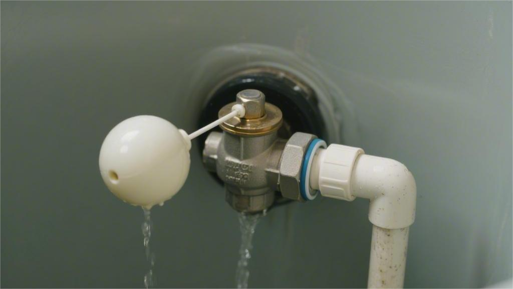
Undersized float valves cause a closing delay of over 10 seconds, resulting in a single overflow of 3 liters; Inferior seals are prone to leakage under 0.5 MPa water pressure. Strict 1:1 sizing matching the pipe diameter is required, paired with a Shore hardness 70 EPDM O-ring, and the static water level must be set 5 cm below the overflow port to ensure a rapid, zero-drip shutoff within 2 seconds, eliminating water waste. Wrong Sizing Under standard municipal water pressure of 60 psi, if a small 4-inch float adapted for a 1/2-inch pipe is incorrectly installed on a 1-inch inlet pipe, the buoyancy it provides is 35% lower than the force required to close the valve. This leaves a 2 mm gap at the valve core, causing a continuous overflow of approximately 1.2 gallons per minute (GPM). Calculated using Los Angeles water rates, a single incorrectly sized float valve wastes over 51,000 liters of clean tap water per month. Proper selection requires strict fluid dynamic matching of the NPT pipe diameter, inlet line system pressure (psi), and the water displacement volume of the float. Pipe Diameter In a conventional 50 psi municipal water supply system, forcing a 3/4-inch inlet pipe into a 1/2-inch float valve via a reducer creates a severe hydrodynamic throttling effect at the valve body inlet. Pipe contraction causes the water flow rate to plummet from the originally designed 22 GPM to 14 GPM. In a 300-gallon outdoor livestock water trough in Arizona, the reduced flow extended the filling cycle from 14 minutes to 22 minutes. The operating time of the water supply system’s booster pump was prolonged, consuming about 1.2 kWh of extra electricity daily. Prolonged low-flow, high-pressure physical impact accelerates metal cavitation within the brass valve body’s internal channels, resulting in wear pits 0.5 mm deep after 7 months of use. On a compact 50-gallon makeup water tank, installing a 2-inch industrial high-flow float valve achieves a filling speed of 120 GPM. The water level rapidly rises to the maximum set point within 25 seconds, and the float pushes the lever and valve core violently toward the inlet with extreme acceleration. The mechanical valve shuts completely within 0.2 seconds, forcefully cutting off the water flowing at 8 feet per second inside the pipe. The fluid’s kinetic energy instantly converts into pressure within the pipe network, generating a transient high-pressure wave up to 400 psi, causing severe physical water hammer damage. Physical Parameter Adaptation Table for Different NPT Pipe Diameters and Tank Volumes Inlet Pipe Diameter (NPT) Standard Flow Rate at 50 psi Recommended Minimum Tank Volume Estimated Water Hammer Pressure from Instant Valve Closure 1/2 Inch 14 GPM 30 Gallons 150 psi 3/4 Inch 22 GPM 75 Gallons 210 psi 1 Inch 35 GPM 150 Gallons 280 psi 2 Inches 120 GPM 1000 Gallons 450 psi Float valves marketed with 1-inch NPT external threads often have actual internal physical water passage holes machined to 3/8-inch or 1/2-inch. In a high-rise rooftop water storage project in Denver, Colorado, engineers selected full-port valves with a 3/4-inch internal bore based on the pipe’s outer diameter. When the water supply network pressure was maintained at 75 psi, the opening water flow resistance generated by the full-port valve was 60% higher than that of a standard bore valve. The system’s original 8-inch polyethylene plastic float could not provide sufficient upward closing force. A steady, unnoticeable overflow of 0.8 GPM occurred at the bottom of the tank, losing over 34,000 gallons of municipal tap water in a month. Physical dimensional differences in interface thread standards cause slow water seepage at pipe connections. The U.S. piping market uses the National Pipe Thread (NPT) standard, processed with a physical taper of 1 degree 47 minutes. Mismatched Thread Angles: Screwing a brass float valve with British Standard Pipe Taper (BSPT) threads into an NPT-spec PVC fitting results in a mechanical deviation of 5 degrees, as their thread angles are 55 degrees and 60 degrees, respectively. Insufficient Engagement Depth: Forcible tightening only guarantees metal engagement for the first 3 threads, leaving a physical gap of 0.1 to 0.3 mm in the subsequent thread sections. Thread Seal Tape Failure: Under a network static pressure of 60 psi, 4 wraps of PTFE thread seal tape will be penetrated by high-pressure water molecules after 48 hours. Quantified Leakage Loss: A trace leakage of 150 ml per hour forms at the thread gap, accumulating a wasted 340 gallons of water resources over a year. When the pipe diameter is undersized and the system pressure exceeds 80 psi, the inlet flow velocity surpasses 12 ft/s. The physical scouring of high-speed water drastically increases the surface roughness of the Nitrile Rubber (NBR) sealing gasket on the valve seat. In a commercial greenhouse irrigation reservoir in Florida, after 6 months of continuous operation, a 3 mm thick rubber gasket was cut by the water flow into a groove 0.8 mm wide. Water continuously dripped into the tank along this microscopic groove at a rate of 5 drops per second, triggering 3 false alarms per day from the bottom groundwater level detector. Brass has a linear expansion coefficient of 1.8×10^-5 per degree Celsius, while 304 stainless steel’s parameter is 1.6×10^-5. In outdoor exposed facilities with day-night temperature differences reaching 40°F, a relative physical displacement of 0.02 mm occurs at the joints of 1.5-inch large-diameter pipes. Repeated thermal expansion and contraction deformation cause microscopic fractures in the industrial sealant within the threads, inducing chronic dripping outward along the pipe wall. On cantilever-mounted PVC inlet pipes, an oversized metal float valve body exerts downward physical gravity torque on the pipe’s end. A 2-inch cast brass float valve, combined with a 12-inch brass lever and a 10-inch copper float, has a total weight exceeding 14 pounds. Installing it on a 1-inch Schedule 40 PVC pipe extension without any bottom bracket support combines gravity with the vertical impact force of water flow opening and closing, subjecting the PVC pipe’s solvent-welded joint to a continuous bending stress
Custom Ball Float Valve Materials Explained for Different Environments | Brass, Stainless Steel, Plastic
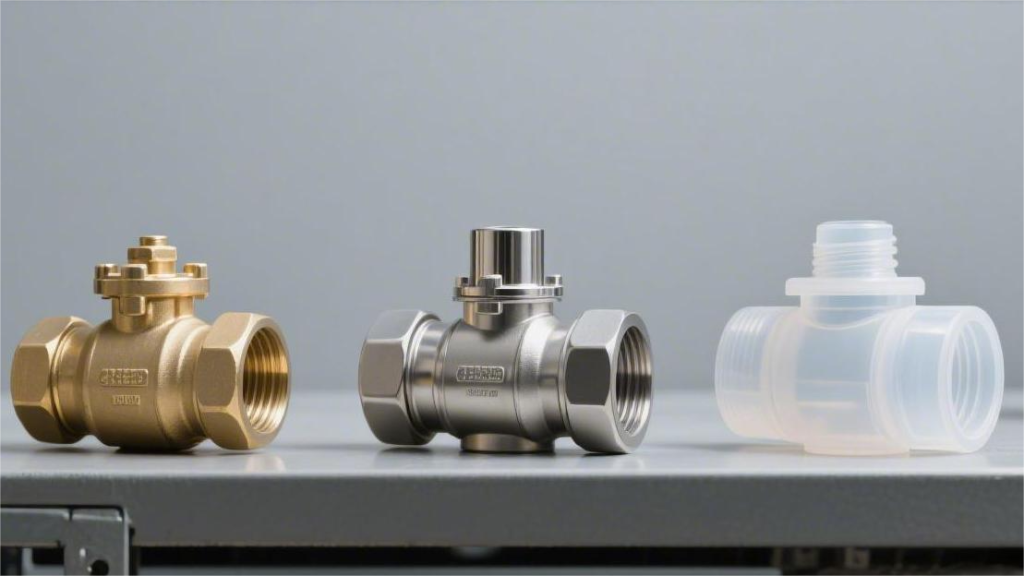
Brass is suitable for civil water systems, bearing pressures of 1.6 MPa and temperatures of 120°C; 316 stainless steel specializes in corrosive chemical environments, with pressure resistance up to 6.4 MPa; Plastics (such as PVC) are ideal choices for electroplating tanks, provided temperature and pressure are strictly limited to within 60°C and 1.0 MPa, respectively. Brass Industrial standard brass consists of approximately 60% copper and 39% zinc. Its tensile strength reaches 330-450 MPa. In neutral water media with a pH value of 6.5-8.5, it can withstand working pressures of 1.0 to 1.6 MPa and continuously tolerate temperatures up to 90°C. In conventional HVAC (Heating, Ventilation, and Air Conditioning) cooling towers or agricultural water storage tanks, the physical lifespan of such valves typically exceeds 5 years. When the chloride ion concentration in the water exceeds 200 mg/L, standard brass undergoes a dezincification reaction, and the annual material corrosion rate exceeds 0.1 mm. Grades & Scenarios Brass matrices under North American standards generally maintain a ratio of 60% copper to 40% zinc, with tensile strengths broadly reaching 310 to 450 MPa. Adding 2.5% to 3.7% lead can provide excellent physical self-lubrication during CNC machining. The machinability rating of C36000 free-cutting brass is set as the industry benchmark score of 100, and the chips produced by lathes break very quickly. A constant yield strength of 310 MPa allows the valve body to easily withstand a static water pressure of 1.5 MPa in the pipe network. A thermal conductivity of 115 W/(m·K) ensures minimal component expansion during alternating hot and cold cycles. It continuously withstands water temperature conditions up to 93°C, provided the fluid’s pH is maintained between 6.5 and 8.0. When placed in car wash reclamation systems or closed-loop cooling towers, the water flow typically only carries trace impurities with Total Dissolved Solids (TDS) below 500 ppm. The physical wear rate of C36000 material in corresponding non-acidic water qualities is less than 0.05 mm per year. Once the chloride ion concentration in the water body rises above 300 ppm, standard formulation brass matrices undergo an irreversible electrochemical reaction. In marine environments or desalination Reverse Osmosis (RO) concentrate pipelines, salt content often exceeds 30,000 ppm. At this point, adding 0.75% to 1.0% tin can form a dense physical barrier of tin oxide on the material’s surface. The American Society for Testing and Materials (ASTM) designates this as C46400 Naval Brass, and its tensile strength correspondingly increases to 380 MPa. Environmental Chloride Concentration Standard C36000 Corrosion Rate C46400 Naval Brass Corrosion Rate Recommended Application Components < 50 ppm 0.01 mm/year < 0.005 mm/year Indoor freshwater storage tank float balls 50 – 500 ppm 0.15 mm/year 0.01 mm/year Coastal agricultural irrigation troughs > 10,000 ppm > 0.50 mm/year 0.08 mm/year Ship ballast water tank level valves For exposed water tanks installed in coastal climates, high concentrations of salt spray in the air adhere to metal surfaces year-round. The yield strength of Naval Brass stabilizes at 170 MPa, normalizing its resistance to mechanical vibration and surface pitting brought by sea breezes. U.S. drinking water systems are strictly governed by the Safe Drinking Water Act (SDWA) and the NSF/ANSI 372 standard. The weighted average lead content of the water-contacting surfaces of all plumbing components is strictly required to be below the 0.25% baseline. To meet this standard, manufacturers blend in 1.5% to 2.0% bismuth or silicon to replace the cutting lubrication effect of lead materials. C89833 bismuth brass completely cuts off the pathway for heavy metals to leach into the water supply network while maintaining good machining characteristics. Ultimate tensile strength remains at 260 MPa, slightly lower numerically than standard leaded alloys. In 82°C hot direct drinking water pipelines, the material’s physical and chemical properties remain absolutely stable. Tested via the EPA Method 200.8, the lead concentration in the leachate of the soaked material is consistently below 1.0 ppb. Commercial water boilers in hotels or pure water make-up tanks in food processing plants handle massive volumes of high-temperature fluids daily. When the water temperature rises above 60°C and the calcium carbonate hardness exceeds 180 mg/L, the zinc element in standard alloys accelerates its dissolution into the water. After dezincification occurs, a porous, sponge-like pure copper skeleton is left inside the valve body, which is prone to physical fracture when subjected to 4.0 bar internal static pressure. Adding 0.02% to 0.15% arsenic in the smelting furnace effectively blocks the ion migration channels within the matrix. The European standard CW602N Dezincification Resistant Brass (DZR) requires validation through ISO 6509 laboratory accelerated corrosion testing. After soaking in a 1% copper(II) chloride solution at 75°C for 24 hours, the dezincification depth of the material is limited to within 200 microns. Water Hardness (CaCO3) Operating Temperature Applicable Alloy Grade Expected Trouble-Free Operation Cycle < 60 mg/L (Soft Water) 20°C – 50°C C36000 100,000 open/close cycles 60 – 180 mg/L 50°C – 75°C C89833 80,000 open/close cycles > 180 mg/L (Hard Water) 75°C – 95°C CW602N (DZR) 120,000 open/close cycles Level control valves in underground reservoirs of high-rise buildings or municipal main water supply networks face normalized hydrostatic pressures of 80 psi to 120 psi daily. The moment a water pump house starts or a valve slams shut, a physical shockwave of water hammer up to 250 psi erupts within the pipeline. The CW617N alloy, pressed using a hot forging process, has a far denser internal metallic grain structure than standard sand-cast parts, completely free of pores. During destructive water pressure testing, forged valve bodies can withstand an ultimate burst pressure of 25 bar (approx. 362 psi) without deformation. Sand-cast C84400 valve bodies are mostly used in gravity-fed agricultural troughs, with an upper safe pressure limit generally capping at 15 bar (217 psi). Even under -10°C freezing conditions, hot-forged brass still retains 90% of its room-temperature Charpy impact toughness. If encountering mine groundwater or highly acidic tailings pond recovery water environments with hydrogen sulfide (H2S) concentrations exceeding 10 ppm, the sulfidation reaction on the metal surface immediately generates a layer of black, flaky
Why Custom Ball Float Valves Matter in Natural Gas Processing | Reliability, Pressure Tolerance, Lifespan
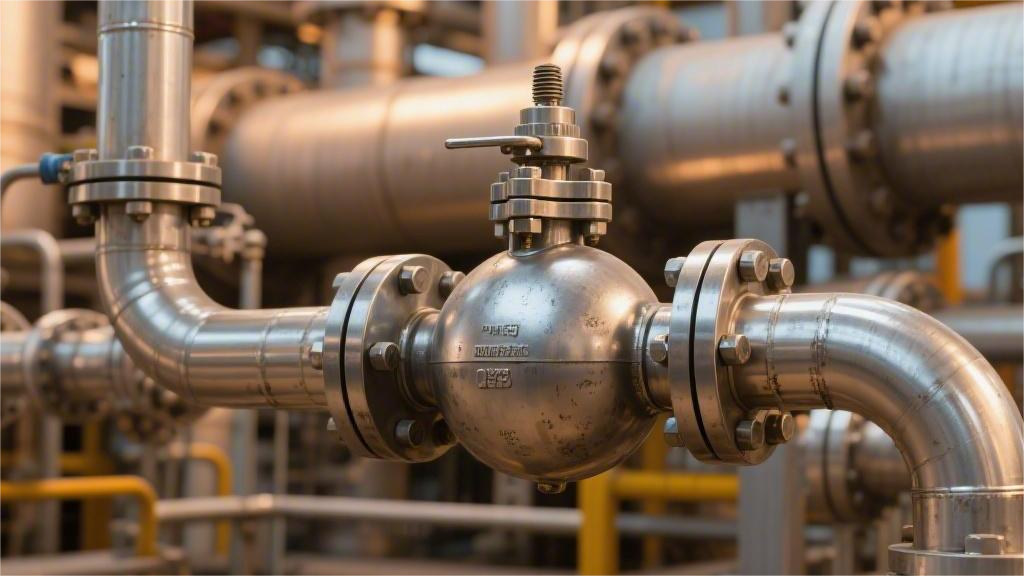
Custom float valves can withstand high pressures up to 25 MPa in natural gas processing. The float counterweight must be precisely calibrated based on a specific gas gravity of 0.65 to prevent malfunction in liquid level control. This ensures extreme reliability at the API 6D level, significantly extending the system’s Mean Time Between Failures (MTBF) to over 50,000 hours. Reliability For severe operating conditions in natural gas separators with H2S concentrations up to 15,000 ppm and entrained sand, custom float valves utilize NACE MR0175-compliant materials and specific buoyancy calculations to increase the Mean Time Between Failures (MTBF) from 3 months for standard components to over 40,000 hours. Adjusting the float wall thickness and leverage ratio based on the user’s specific process parameters (such as a liquid specific gravity range of 0.3 to 0.8) ensures that the valve does not experience mechanical binding under a 50 Hz vibration frequency and a 1500 psi pressure drop. This design reduces the unplanned downtime rate by 90% and achieves ANSI/FCI 70-2 Class VI shutoff requirements, guaranteeing continuous system operation. Materials & Operating Conditions In the wellhead effluents of the Haynesville Shale gas field in North America, the hydrogen sulfide concentration is consistently maintained between 15,000 ppm and 25,000 ppm year-round, with a carbon dioxide volume fraction reaching 10% to 12%. The initial pressure of local gas wells is as high as 10,000 psi, and fluid temperatures generally exceed 120°C, accompanied by large amounts of formation sand and highly concentrated brine. Commercially available standard 316L stainless steel float valves have an average service life of only 45 to 60 days in highly acidic and corrosive environments. Once the chloride ion concentration in free water exceeds 50 mg/L and the temperature rises above 60°C, the 316L surface is highly susceptible to pitting and stress corrosion cracking, leading to float perforation, water ingress, and a complete loss of buoyancy. Customizing valve materials based on fluid chemical composition analysis reports is a fundamental physical requirement to prevent early equipment failure. For high-chloride conditions containing free water, super duplex stainless steel (such as SAF 2507) is extensively used; its Pitting Resistance Equivalent Number (PREN) is greater than 42, and its yield strength reaches 80,000 psi, allowing it to withstand severe pressure pulses. At the bottom of desulfurization towers with extremely high H2S concentrations, the NACE MR0175/ISO 15156 standard strictly limits the hardness of metals exposed to sour gas. Due to its copper-nickel composition ratio, Monel 400 alloy exhibits an extremely low corrosion rate of less than 0.02 mm per year in oxygen-free liquid hydrocarbons with high concentrations of H2S. Gas Well Fluid Characteristics Typical Operating Data Recommended Custom Alloy Expected Corrosion Resistance Metrics High Chlorides + High Temperature Chloride Ions > 10,000 ppm, 150°C Super Duplex Stainless Steel 2507 Zero Stress Corrosion Cracking Record Extremely High H2S Concentration H2S > 20,000 ppm, 100°C Monel 400 Corrosion Rate < 0.02 mm/year High Acidity + High CO2 CO2 > 15%, pH < 3.5 Hastelloy C-276 PREN > 45, No Pitting Severe Erosion + Sand-bearing Solid Particles > 2%, 10 m/s Flow Velocity Inconel 625 Surface Hardening Rockwell Hardness up to 70 HRC The specific gravity (SG) of the liquid inside a natural gas condensate separator is typically between 0.45 and 0.65, which is far lower than water’s 1.0. This extremely low medium density requires the float to provide sufficient mechanical upward buoyancy within a limited volume to push open a valve trim subjected to a 2000 psi differential pressure. When calculating buoyancy, the manufacturer must determine the fluid density at the operating temperature accurately to three decimal places. If the condensate SG is 0.50, under a 1500 psi system backpressure, the outer diameter of the custom float typically needs to be expanded to 8 inches (203.2 mm), with the sphere’s internal volume reaching 4180 cubic centimeters. While increasing the volume, the float wall thickness must concurrently be increased to 3.0 mm to 4.5 mm to prevent high-pressure gas from collapsing the sphere. An 8-inch float manufactured from Hastelloy C-276 with a wall thickness of 4.0 mm has a dead weight of approximately 2.2 kg, producing a net displaced mass of about 2.09 kg in a liquid with an SG of 0.50. Custom Temperature Resistance for Sealing Surface Materials: Standard Polytetrafluoroethylene (PTFE) valve seats experience cold flow deformation at 150°C, leading to seal failure. Custom solutions utilize Polyether Ether Ketone (PEEK) to machine the valve seats, withstanding the dual physical loads of 260°C high temperatures and 3000 psi pressure. Anti-wear Treatment for Sand-bearing Fluids: Natural gas in the Appalachian Basin frequently entrains quartz sand particles. The contact surfaces of the valve trim and seat require High-Velocity Oxygen Fuel (HVOF) spraying to apply a 0.2 mm thick tungsten carbide coating, preventing the sealing surfaces from forming grooves under high-speed gas-liquid erosion. Anti-fatigue Material Selection for Springs and Pins: The internal return springs and leverage pins of the valve operate under peak stress conditions. Springs manufactured from Inconel X-750 alloy undergo 1 million compression cycles at 200°C high temperatures with an elasticity decay rate of less than 2%. The contact angles between the sealing surface and the valve seat are typically machined with a specific taper angle difference (e.g., 45 degrees for the trim, 46 degrees for the seat) to form an extremely narrow line-seal contact band. High-pressure fluid acting on this minute area generates extremely high specific pressure, achieving an ANSI/FCI 70-2 Class VI leakage rate even without rubber gaskets. Medium Specific Gravity (SG) Maximum System Pressure Drop (psi) Custom Float Outer Diameter Requirement Custom Lever Arm Length Ratio 0.45 1000 8.0 inches 1 : 6.5 0.55 1500 7.5 inches 1 : 5.8 0.65 2000 7.0 inches 1 : 5.0 0.80 3000 6.0 inches 1 : 4.2 Pre-factory material verification procedures are extremely strict, including Positive Material Identification (PMI) spectral analysis. Handheld X-ray fluorescence spectrometers scan the surfaces of the valve body, flanges, float, and fasteners to read the mass percentages of each element. Taking Inconel 625 components as an example, the
How to Choose a Custom Ball Float Valve for Natural Gas Systems | Material, Pressure Rating, Seal Integrity
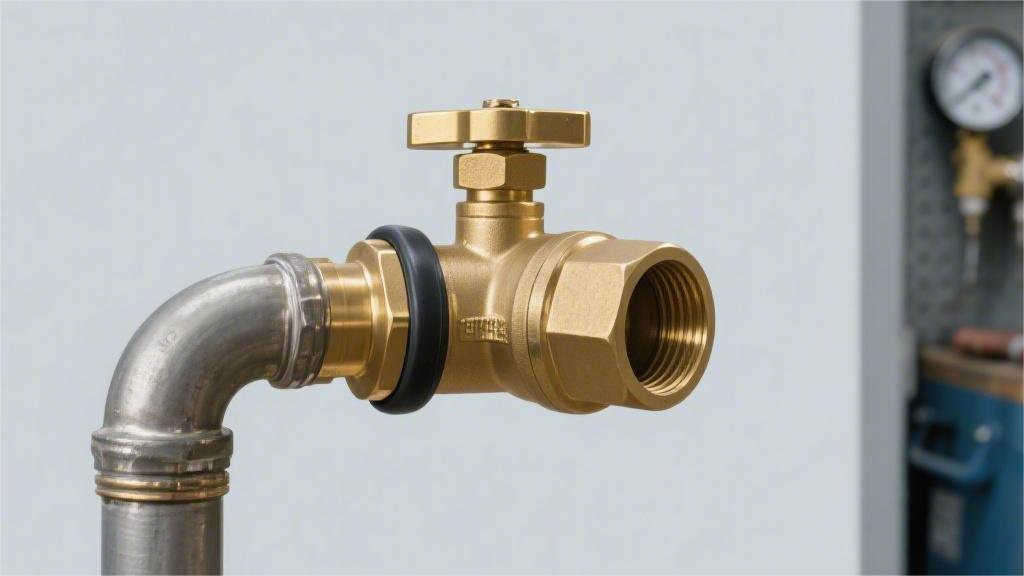
Custom natural gas float valves must prioritize Inconel alloys to prevent sulfur corrosion. The selected pressure rating must exceed the system peak by 20%, and PEEK seals should be used to ensure ANSI Class VI zero leakage across a wide temperature range. A hydrostatic test at 1.5 times the design pressure must be performed for verification prior to installation. Material Dry natural gas (moisture < 7 lbs/MMscf) mostly uses ASTM A105 carbon steel, with pressure resistance up to 10,000 psi. When the H2S partial pressure exceeds 0.3 kPa, the NACE MR0175 standard requires the use of 316L stainless steel or duplex stainless steel (such as UNS S31803), and the metal Rockwell hardness must be below HRC 22. The float body is commonly made of seamless 316 stainless steel with a wall thickness of 0.5-2.0 mm, manufactured via Tungsten Inert Gas (TIG) welding. Non-metallic seals in the -40°C to 200°C range mostly use Anti-Explosive Decompression (AED) grade FKM or PTFE materials. Metal Selection & Environment Conventional gas gathering pipelines in the Permian Basin operating at 600 psi require completely different materials than offshore platforms in the North Sea processing high-salinity aerosols. For non-corrosive sweet gas environments containing less than 4 ppmv of hydrogen sulfide, the base material is forged carbon steel compliant with the ASTM A105 standard. ASTM A105 forgings contain a maximum of 0.35% carbon and 1.05% manganese, providing a minimum tensile strength of 70,000 psi (approximately 485 MPa). This material performs well within a temperature range of -29°C to 425°C. When exposed to untreated natural gas with a water content exceeding 7 lbs/MMscf, bare carbon steel will experience uniform corrosion at a rate of up to 0.5 mm per year. The external surface is sprayed with a Fusion Bonded Epoxy (FBE) coating 250 microns thick to mitigate oxidation. Internal fluid passages often utilize Electroless Nickel Plating (ENP) with a thickness of 3 mils, complying with the ASTM B733 standard. Moving to cold climate regions like the Bakken Formation in North Dakota, ambient temperatures often drop below the -29°C lower limit of A105. Low-Temperature Carbon Steel (LTCS) of the ASTM A350 LF2 specification replaces conventional A105 in sub-zero environments. LF2 material undergoes a normalizing heat treatment to refine the grain structure to maintain ductility. It must pass a Charpy V-notch impact test at -46°C, absorbing at least 20 Joules of energy without brittle fracture. Condensate water in the natural gas stream mixed with carbon dioxide (CO2) will trigger sweet corrosion, generating carbonic acid. Under conditions where the CO2 partial pressure exceeds 3 psi, the degradation rate of carbon steel rises exponentially. Austenitic stainless steel becomes the minimum entry standard for the system: ASTM A182 F316 contains 16% chromium, 10% nickel, and 2% to 3% molybdenum. The molybdenum element increases the Pitting Resistance Equivalent Number (PREN) to 24, forming a stable passive oxide film on weakly acidic surfaces. When welding valve components, the low-carbon variant 316L (carbon upper limit 0.03%) prevents chromium carbide precipitation at the grain boundaries. Chlorides will attack the passivation layer of 316L, triggering localized pitting and Chloride Stress Corrosion Cracking (CSCC) at temperatures above 60°C. Duplex stainless steel bridges the performance gap between austenitic grades and expensive nickel alloys. UNS S31803 (Standard Duplex) and UNS S32750 (Super Duplex) feature a dual-phase microstructure consisting of 50% austenite and 50% ferrite. S32750 contains 25% chromium, 7% nickel, and 4% molybdenum, pushing its PREN value above 40. The unique metallurgical structure provides a yield strength of 550 MPa, allowing for reduced wall thickness while maintaining a 10,000 psi burst pressure limit. ASTM Standard Unified Numbering System (UNS) Alloy Composition Ratio (%) PREN Value Environmental Condition Limits Extreme Operating Temperature Range A105 K03504 C:0.35, Mn:1.05 – Completely dry natural gas, H2S < 4ppmv -29°C to 425°C A350 LF2 K03011 C:0.30, Mn:1.35 – Gas pipelines in extreme cold regions, requiring low-temperature impact toughness -46°C to 425°C A182 F316L S31603 Cr:16-18, Ni:10-14, Mo:2-3 24 CO2 partial pressure > 3psi, mildly saline -196°C to 450°C A182 F51 S31803 Cr:22, Ni:5.5, Mo:3, N:0.15 35 Marine atmosphere, max chlorine content 20,000 ppm -50°C to 280°C A182 F53 S32750 Cr:25, Ni:7, Mo:4, N:0.28 >40 FPSO platforms, high-frequency salt spray attacks -50°C to 280°C B564 N06625 Ni:58, Cr:21, Mo:9, Nb:3.6 >45 Contains liquid water, H2S partial pressure > 0.3 kPa -196°C to 815°C Prolonged exposure to temperatures exceeding 280°C will lead to the precipitation of the α’ phase, defined as the “475°C embrittlement” phenomenon, which significantly reduces impact toughness. In hyper-sour gas reservoirs such as those in the Middle East, hydrogen sulfide (H2S) concentrations can reach up to 10%. High concentrations of H2S strictly mandate compliance with API 6D and NACE MR0175 specifications, employing solid nickel-based alloys. Inconel 625 (UNS N06625) possesses extremely high immunity to Sulfide Stress Cracking (SSC). It contains 58% nickel, 21% chromium, and 9% molybdenum, with the addition of up to 4.15% niobium for solid-solution strengthening. A 4-inch API Class 1500 Inconel 625 float valve weighs approximately 180 kilograms and costs five times as much as its 316L counterpart. To balance capital expenditure, manufacturers often employ cladding technology. Gas Tungsten Arc Welding (GTAW) is used to deposit a 3mm thick layer of Inconel 625 onto the internal wetted surfaces of the A105 carbon steel valve body. The iron content upper limit on the surface of the overlay is set at 5% to maintain the corrosion-resistant properties of Inconel. Hardness testing is used to verify that the Heat-Affected Zone (HAZ) does not exceed 22 HRC (237 HBW), meeting the restrictive conditions for NACE sour service. The pivot pins and valve stems operating the float mechanism endure high shear forces and continuous friction. Valve stem materials commonly utilize precipitation-hardening stainless steels such as 17-4 PH (UNS S17400). After subjecting the steel to a one-hour aging treatment at 480°C (H900 condition), its tensile strength can reach 1,310 MPa. 17-4 PH is prone to hydrogen embrittlement in sour environments, and its excessive hardness fails to comply with NACE MR0175 requirements. In pipelines handling H2S, the valve stem
What Causes Ball Float Valve Leaks in Gas Systems? | Pressure, Sealing & Material Issues
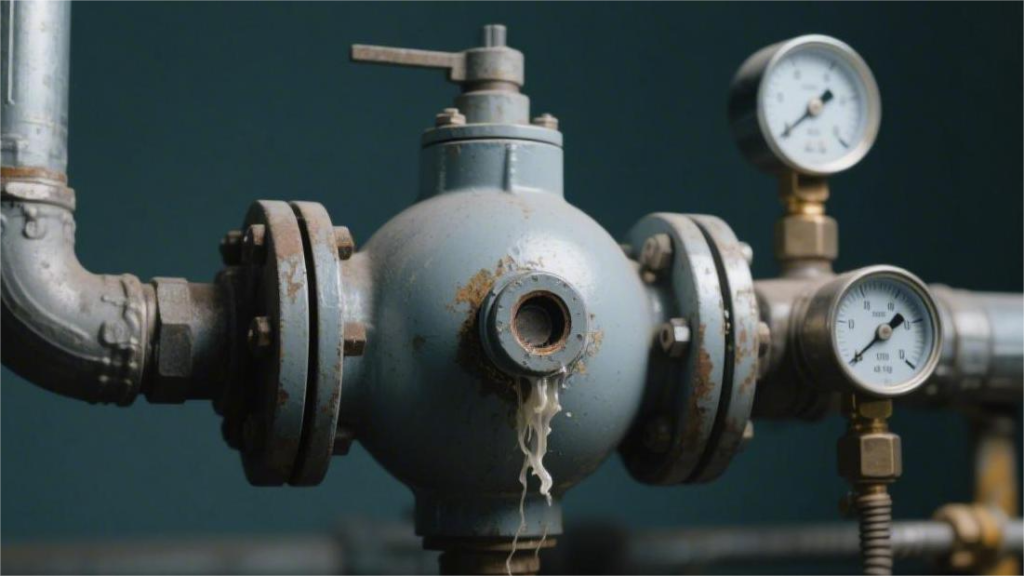
The primary cause of gas leakage is the 15% plastic deformation of the sealing seat triggered by pressure surges. A sealing ring with a hardness of Shore A 85 should be selected to prevent high-pressure permeation, but cold embrittlement failure at -20°C must be guarded against. It is recommended to control the pressure drop within 0.5 MPa to mitigate cavitation, and to use an ultrasonic detector to monitor abnormal noises above 50 decibels, ensuring that zero-bubble sealing can still be achieved under 10% pressure fluctuations. Pressure When the system pressure exceeds the yield strength of the sealing seat material (for example, PTFE is approximately 15-22 MPa at 23°C), a plastic cold flow on the 0.1mm level will occur, resulting in permanent deformation of the sealing surface. Conversely, if the pressure is below 0.3 Bar, the self-tightening sealing structure driven by the medium will fail to compensate for the microscopic surface roughness (typically Ra 0.8 or higher) due to insufficient preload, triggering bubble leakage outside the API 598 standard. High Pressure Deformation When the pipeline pressure is elevated to the Class 900 rating (approximately 15.3 MPa), the linear thrust exerted by the ball on the valve seat is converted into surface contact pressure. If this pressure exceeds the yield limit of the PTFE valve seat at 23°C, which is about 18 MPa, the material will undergo inelastic displacement. This physical displacement manifests as the sealing seat being squeezed towards the valve body cavity, destroying the original flatness of the Ra 0.4 sealing surface. After a sustained high-pressure load for 48 hours, the edge of the sealing ring will experience an elongation of 0.2mm to 0.5mm. This phenomenon is known as “extrusion” in the valve maintenance industry. Once the material extrudes, the ball will shear off the protruding sealing surface when it rotates to open, resulting in the inability to form a continuous sealing ring during the next closure. RPTFE (15% glass fiber reinforced): Compressive resistance is improved by 30% compared to pure PTFE, but there is still a 2% deformation rate at 10 MPa pressure. PEEK (Polyether Ether Ketone): Suitable for extreme environments above 25 MPa, with a hardness of Rockwell M95, capable of effectively resisting geometric distortion under high pressure. Metal-to-Metal Seal: Utilizes Stellite 6 hard alloy overlay welding, maintaining micron-level deformation at 42 MPa pressure, suitable for high pressure differential shut-off. When the pressure rises rapidly from 5 MPa to 20 MPa, the ball not only displaces horizontally but also compresses the thickness of the downstream sealing seat. This thickness reduction causes a slight offset in the central axis of the valve stem, typically between 0.05mm and 0.15mm. This axial offset compresses the upper packing set, subjecting the V-ring packing originally intended for gas sealing to uneven lateral forces, increasing the probability of gas leaking from the valve stem. Because gas molecules have extremely strong penetrability, high-pressure deformation will generate microscopic cracks inside the valve seat. These cracks are usually under 10μm in diameter and are difficult to detect with the naked eye. According to the Class A test requirements of the EN 12266-1 standard, the bubble leakage rate should be zero. However, under the effect of high-pressure deformation, the effective contact width of the sealing pair will abnormally increase from 3mm to 5mm, which in turn reduces the specific sealing pressure per unit area. Sealing surface topology change: High pressure forces the ball to embed into the valve seat, changing the contact point from a “line” to a “band,” and the friction force simultaneously increases by 40%. Elastic modulus failure: When the ambient temperature rises to 150°C, the elastic modulus of PTFE decreases by 60%, and high-pressure deformation becomes irreversible. Packing load fluctuation: High pressure causes the valve body cavity to expand, and the connecting bolts stretch by about 0.02%, resulting in a decrease in pressure on the flange sealing surface. Ball offset risk: Under Class 2500 conditions, the total thrust generated by the pressure differential on the ball can reach several tons; if the support bearings deform, it will cause the valve to jam during opening and closing. Within the pressure boundaries defined by the ASME B16.34 standard, the creep resistance of the material determines the degree of deformation. For hydrogen pipelines where the working pressure is maintained above 100 Bar year-round, Devlon V-API material is typically selected, as its water absorption rate is below 0.1% and it possesses extremely high dimensional stability. If ordinary engineering plastics are used, high pressure will cause molecular chain slippage, and after 500 closing cycles, the internal leakage rate of the valve will downgrade from Rate A to Rate D. Because deformation increases the static friction coefficient between the ball and the valve seat (from 0.05 to over 0.15), the pneumatic actuator may not be able to overcome the starting torque under a 0.6 MPa air supply pressure. This torque surge caused by deformation is typically 1.5 times higher than the design calculation value, leaving the valve in a partially open/partially closed state, further exacerbating the physical damage caused by high-pressure gas scouring the sealing surface. Pressure Class Working Pressure (PSI) Recommended Sealing Material Maximum Allowable Deformation Rate (%) 150 285 PTFE / NBR < 5.0% 600 1480 RPTFE / NYLON < 2.0% 1500 3705 PEEK / DEVLON < 0.5% 2500 6170 Tungsten Carbide < 0.01% Under frequent operating conditions of opening and closing once per minute, the sealing seat material will generate heat due to repeated compression and release, and the local temperature may be 20°C higher than the medium temperature. Low Pressure Failure The design standards for floating ball valves dictate that the ball must fit closely against the valve seat driven by downstream differential pressure. However, when the pipeline pressure falls below 0.3 Bar, the gas thrust cannot overcome the initial elastic resistance of the seat material. This insufficient thrust results in a micrometer-level physical gap between the ball and the valve seat. According to the API 598 standard, low-pressure gas tightness testing is typically conducted at
What Affects Ball Float Valve Lifespan in Harsh Gas Environments? | Material Quality, Contaminants, Pressure Fluctuations
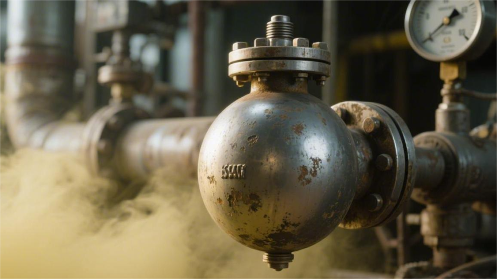
In harsh gas environments, the lifespan of spherical float valves is collectively influenced by material corrosion resistance, particle erosion, and pressure fluctuations. Selecting 316L stainless steel or Hastelloy can extend service life by 2 to 3 times compared to standard materials. If the hydrogen sulfide H2S content in natural gas exceeds 10%, metal surfaces are prone to stress cracking, requiring hardening treatments to increase durability. A 50-micron filter should be installed to reduce particle wear, and pressure fluctuations should be controlled within 15% of the rated value. Periodically testing the sealing specific pressure of the closure members ensures the system maintains zero leakage even after 10,000 continuous cycles. Material Quality In environments where H2S partial pressure exceeds 0.05 psi, compliance with NACE MR0175/ISO 15156 standards is mandatory. Selecting 316L stainless steel or 2205 duplex steel resists chloride-induced cracking; metal hardness must be kept below 22 HRC to prevent hydrogen embrittlement. Non-metallic seals like FFKM retain elasticity even at 320°C, with a volume swell rate below 5%, effectively preventing high-pressure leakage. Metal Alloys In harsh gas processing, the selection of metal alloys is directly governed by ISO 15156 or NACE MR0175 standards. For operating conditions with H2S partial pressure above 0.05 psi, carbon steel must undergo hardness-limited treatment for pressure vessels, with hardness not exceeding 22 HRC. When selecting 316L stainless steel, its molybdenum content must be > 2.0% to maintain a PREN value above 24. In environments exceeding 150°C with chloride levels reaching 50,000 ppm, switching to 2507 super duplex steel or Inconel 625 can keep the annual corrosion rate below 0.01 mm. For float valves in high-pressure gas pipelines, the yield strength of the metal material is the primary consideration. ASTM A182 F316L, an austenitic stainless steel, typically has a yield strength around 205 MPa, suitable for standard natural gas conditions in Class 150 to Class 600 pressure ratings. When operating pressure rises above Class 1500 (approx. 25 MPa), the wall thickness requirement for 316L increases sharply, making the float too heavy. Switching to 2205 duplex steel (UNS S31803) at this point provides a yield strength of 450 MPa, maintaining structural integrity while reducing weight by 40%. Pitting on metal surfaces is primarily induced by chloride ions, with the evaluation metric being PREN (Pitting Resistance Equivalent Number). The calculation involves percentages of chromium, molybdenum, and nitrogen. Standard 304 stainless steel has a PREN of only 18; in wet gas environments containing condensate, micron-scale pitting can be observed within 72 hours. The table below shows a comparison of pitting resistance performance for four mainstream alloys under different media concentrations: Alloy Grade Main Composition (Cr/Ni/Mo) PREN Value Max Chloride Concentration (ppm) 316L 17 / 12 / 2.5 24-26 < 5,000 904L 20 / 25 / 4.5 34-36 < 20,000 2205 22 / 5 / 3.2 35 < 30,000 2507 25 / 7 / 4.0 42 < 100,000 In Sour Gas environments, Hydrogen-Induced Cracking (HIC) is the primary form of metal failure. Free hydrogen atoms permeate the metal lattice and accumulate at inclusions to form internal pressure. Selecting steel treated with the Electroslag Remelting (ESR) process can keep sulfur content below 0.002%, reducing hydrogen accumulation sites. Monel K-500 (UNS N05500), a nickel-copper alloy, performs excellently when handling hydrofluoric acid or high-velocity sandy gas. It possesses not only high hardness but also excellent thermal conductivity, allowing it to quickly dissipate local heat generated by high-frequency vibrations and prevent thermal fatigue cracks on the sealing surface. For high-temperature steam valves exposed to 200°C or higher for long periods, Incoloy 825 is more stable than ordinary stainless steel. Its nickel content of up to 40% and added titanium stabilizing elements prevent intergranular corrosion in the weld heat-affected zone. A potential difference between the seat bracket and the ball can trigger galvanic corrosion. For example, if aluminum bronze parts are in contact with stainless steel in the presence of an electrolyte (such as salt water), the aluminum bronze, acting as the anode, will erode at a rate of 2 mm per year, causing the float bracket to detach. The table below details the potential differences for various alloy combinations in a standard marine atmosphere: Material Combination Potential Difference (mV) Corrosion Risk Level Recommended Measure 316L / Monel 400 50 – 100 Low No special treatment needed 316L / Carbon Steel 400 – 600 High Add insulation coating Duplex Steel / Nickel Alloy 20 – 50 Extremely Low Best compatible combination Hastelloy C276 is the preferred material for extreme reducing environments, such as high-concentration hydrochloric acid gas. Its molybdenum content is as high as 16%, with a tungsten content of 4%. This composition forms a dense, chromium-rich oxide film on the metal surface that repairs itself 10 times faster than ordinary stainless steel. The manufacturing process of the float also impacts material quality. When using ASTM A351 CF8M castings, internal porosity often ranges from 1% to 3%. Under high-pressure conditions, these tiny pores become stress concentration points. In contrast, ASTM A182 forgings undergo three-dimensional forging, where grain flow lines follow the direction of stress, improving impact resistance by 50%. In cryogenic conditions (such as LNG flash gas at -196°C), metals undergo ductile-to-brittle transition. Carbon steel becomes as brittle as glass below -29°C. 300 series austenitic stainless steel must be selected, as its face-centered cubic structure ensures it maintains impact toughness exceeding 50 J even near absolute zero. The ferrite content in the alloy requires precise control. For welded stainless steel floats, the Ferrite Number (FN) should be between 3 and 8. Content that is too low is prone to hot cracking, while content that is too high (over 10%) leads to rapid deterioration in the 475°C embrittlement zone or corrosive environments. In pipelines with severe sand-washing wear, simply increasing hardness results in decreased toughness. By performing ion nitriding on a 410 stainless steel base, hardness can be increased to 60 HRC within a 0.2 mm surface depth. This gradient material design blocks erosion from sand particles over 200 microns without causing the component to shatter under
What’s the Difference Between Trunnion Mounted Ball Valves and Floating Ball Valves | Pressure Handling, Torque Requirements, Sealing Stability
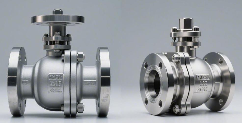
Floating ball valves rely on fluid pressure to push the ball and compress the downstream seal, making them suitable for low-pressure applications below Class 300. Trunnion mounted ball valves have the ball secured by upper and lower shafts, relying on springs to actively push the seats for sealing, capable of withstanding high pressures above Class 600. Because the ball is restrained from shifting under pressure, the sealing of trunnion ball valves is extremely stable, and the operating torque is reduced by approximately 40% compared to floating types, making manual opening or closing smoother and less strenuous in high-pressure systems. Pressure Handling Floating ball valves rely on fluid differential pressure to push the ball toward the downstream seat to achieve a seal. This unidirectional loading restricts their application range to ASME Class 300 (approximately 51 bar) and pipe diameters of 8 inches and below. Exceeding these limits causes plastic deformation in soft seats like polytetrafluoroethylene (PTFE). Trunnion mounted ball valves absorb the entire fluid thrust through the top stem and bottom fixed shaft, utilizing spring-loaded seats to actively press inward against the ball instead. This structure transfers the medium’s thrust to the metal valve body, enabling it to withstand extreme high-pressure environments of Class 2500 (approximately 425 bar) or API 15,000 psi, with compatible pipe sizes reaching up to 60 inches. Differences in Force Transmission Paths Total thrust is calculated according to the ASME B16.34 standard, which is the fluid pressure multiplied by the cross-sectional area of the ball exposed to the flow. A 12-inch natural gas pipeline operating at 1000 psi (approximately 69 bar) has an internal cross-sectional area of about 113 square inches. The total fluid thrust acting on the closed valve ball reaches 113,000 pounds (about 51 metric tons). The way a floating ball valve handles this thrust is by allowing the ball to act as a piston. The bottom end of the stem features a flat drive slot that forms a loose fit with a machined groove at the top of the ball. This fit allows the ball to have a free displacement of 0.5 to 2 millimeters in the direction of the fluid. The 113,000-pound thrust pushes the ball off the centerline, applying the full load onto the downstream ring of the non-metallic seat. 100% of the thrust is concentrated on the single downstream PTFE seat ring. Contact surface stress increases linearly in multiples with pipeline pressure. Cold flow extrusion of the polymer occurs under conditions exceeding 8 inches or Class 300. The upstream seat loses physical contact and sealing function after the ball shifts. The downstream seat, bearing the 51-ton thrust, typically has a width of only 15 to 25 millimeters. The extremely narrow contact band causes the localized localized pressure per unit area to far exceed the standard PTFE material’s yield strength limit of approximately 14 MPa. The high pressure forces the soft seat to be squeezed into the mechanical gap between the ball and the metal valve body. The moment the valve opens, the sharp edges of the ball bore will shear off the extruded polymer material. The mechanical path of a trunnion ball valve transfers the thrust to a high-strength forged steel shell. Both ends of the ball are secured inside the valve body by solid metal upper and lower trunnions. ASME specifications mandate that the trunnions must be integrally forged with the ball, or connected via deep-penetration welding and high-strength pins. The 113,000-pound fluid thrust is transmitted through the trunnions to metal bearings coated with low-friction materials. Self-lubricating bearings typically use a 316 stainless steel substrate with sintered bronze powder, impregnated with PTFE and lead. These composite bearings, measuring only 1.5 to 2.5 millimeters in thickness, can withstand extremely high radial loads of up to 250 MPa. The thrust is laterally distributed by the trunnions into the upper and lower bearing block areas of the valve body. The main load-bearing component thus becomes the forged metal shell of ASTM A105 or A350 LF2, with wall thicknesses reaching 50 to 100 millimeters. Medium thrust is directed into the upper and lower bearings via solid metal trunnions. The high-strength forged valve body absorbs over 99% of the fluid static thrust. The ball remains absolutely physically stationary along the vertical centerline. Bearings absorb radial forces to prevent the ball from shifting and rubbing the seats. Trunnion ball valves utilize a dual active seat design, where the back of each seat ring is equipped with multiple cylindrical helical springs or Belleville springs. Per API 6D specifications, the springs are manufactured from high-nickel alloys like Inconel X-750 or Nimonic 90. The springs provide continuous initial preload, pushing the metal seats against the stationary ball. A precisely calculated piston effect area is designed behind the seats. Pipeline fluid enters the annular cavity behind the seat ring, utilizing differential pressure to push the seat tightly against the ball surface. The force endured is simply the pressure multiplied by the narrow annular pressure-bearing area, which is an order of magnitude—more than 10 times—difference compared to a floating ball valve bearing the thrust of the entire pipe cross-section. Taking a 24-inch pipeline under Class 900 (about 153 bar) as an example, the total thrust exceeds 1 million pounds. If a floating design were used, the ball and seat would be instantly crushed. The thrust borne by the back of the active seat in a trunnion ball valve might only be 30,000 pounds. Manufacturers adjust the placement of the O-rings and polymer lip seals at the back of the seat to control the compressive force within a reasonable range that will not crush sealing materials like Devlon or Nylon. Inconel alloy springs provide 0.5 to 1.5 MPa of initial preload. Auxiliary pressure build-up utilizes fluid differential pressure across the tiny area at the back of the seat ring. Spring preload and fluid pressure combine to achieve ball conformity. O-rings and graphite packing block fluid from escaping from the back of the seat. Under differential pressure, a floating ball valve generates
Best Materials for Custom Trunnion Mounted Ball Valves in Corrosive Environments | Duplex Stainless Steel, Inconel Alloys, and Hastelloy
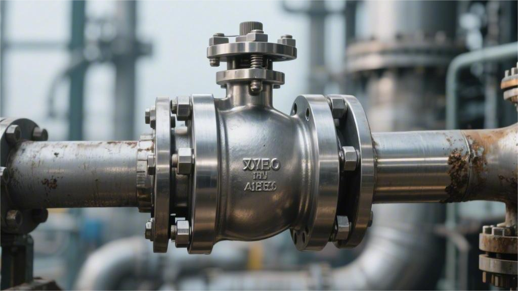
For chlorine-containing environments, choose 2205 duplex stainless steel with a PREN over 35; for high-temperature sulfur-containing environments, use Inconel 625 with over 58% nickel; for strong acids, pair with Hastelloy C-276. During manufacturing, the interpass temperature of the weld must be controlled below 150°C to prevent intergranular corrosion. Duplex Stainless Steel Mainly comprising UNS S32205 (2205) and S32750 (2507 super duplex stainless steel), their PREN values reach above 35 and 42 respectively. In chlorine-rich and H2S environments complying with the NACE MR0175 specification, DSS can block stress corrosion cracking. For high-pressure systems above ASME Class 1500, designers can reduce the valve body wall thickness according to standards, and the material procurement cost is typically 40% to 60% lower than that of Inconel 625. Metallographic Ratio In the forging standard for fixed ball valves, the factory setting is 50% austenite and 50% ferrite. According to the NORSOK M-630 specification, the ferrite content of qualified valve pressure boundary materials must be controlled within the range of 35% to 55%. Adjusting the two-phase ratio relies on chemical element ratio control during the smelting stage. Chromium (Cr) and molybdenum (Mo) are ferrite-forming elements, while nickel (Ni) and nitrogen (N) promote austenite formation. Taking UNS S32205 as an example, smelters must strictly control the nitrogen content between 0.14% and 0.20% to offset the excessive transformation of the heat-affected zone (HAZ) into ferrite during welding. The addition of nitrogen balances the phase ratio and improves the localized corrosion resistance index of the austenite phase. When the nitrogen content reaches 0.2%, the material’s overall pitting resistance equivalent number (PREN) stabilizes above 35. Since the chromium and molybdenum content in austenite is lower than in ferrite, adding nitrogen compensates for the austenite phase’s vulnerability to pitting in seawater. The solution annealing temperature determines the final metallographic equilibrium state of the product. The solution treatment temperature for 2205 duplex steel is set between 1020°C and 1100°C. When the temperature reaches 1050°C, the volume ratio of the two phases is closest to 1:1. After heating, water quenching is performed at a cooling rate greater than 1.5°C/second to prevent ferrite from undergoing phase transformation during cooling. A cooling rate lower than the aforementioned standard will cause intermetallic compounds to precipitate in the temperature range of 700°C to 1000°C, with the Sigma (σ) phase being the most common. The Sigma phase is rich in chromium and molybdenum; it strips anti-corrosion elements from the matrix, leading to localized chromium-depleted zones. A 1% volume precipitation of Sigma phase will reduce the material’s Charpy impact absorbed energy by more than 50%. Industrial standard procedures for inspecting the phase ratio of valve body materials include using a magnetic ferrite meter and a metallographic microscope. Non-destructive testing on-site often utilizes a Fischer ferrite meter to read the Ferrite Number (FN) according to the AWS A4.2 standard. For destructive testing of valve bonnets or ball slices, laboratories perform a systematic point count evaluation based on ASTM E562. According to the test requirements, technicians use a 100-point grid to cover the polished and etched specimen surface under a 400x optical microscope. Technicians randomly select at least 20 fields of view in different areas of the specimen for counting. The error of the calculated average ferrite percentage is controlled within ±2%, complying with the API 6D valve material acceptance specification. According to the test specifications of ASTM G48 Method A, duplex stainless steel must be immersed in a 6% ferric chloride solution for 24 hours. The testing temperature for 2205 material is usually set at 22°C or 25°C, while the test temperature for 2507 super duplex stainless steel is raised to 50°C. After removal, the specimen’s surface condition must be observed under a 20x microscope. Any pitting crater with a depth exceeding 0.025 mm will cause the specimen to fail. For specimens meeting the 50:50 metallographic ratio requirement, the overall weight loss must be less than 4.0 g/m². Failing weight loss data usually indicates a phase imbalance within the material or localized precipitation of harmful chromium-rich phases. To quantify the specific contributions of different metallographic structures to the performance of fixed ball valve components, the table below illustrates the mechanical and chemical characteristic parameters of the main phases. Metallographic Phase Type Crystal Structure Characteristics Typical Volume Percentage Yield Strength Contribution (MPa) Corrosion Resistance Manifestation Ferrite (Alpha) Body-Centered Cubic (BCC) 40% – 50% +250 to +350 Resists Stress Corrosion Cracking (SCC) Austenite (Gamma) Face-Centered Cubic (FCC) 50% – 60% +150 to +200 Resists Localized Pitting Sigma Phase (σ) Tetragonal < 0.5% (Required) Causes severe material embrittlement Consumes surrounding matrix Cr and Mo elements The high heat input of arc welding causes the weld pool and heat-affected zone to instantly reach over 1300°C, and this area transforms into ferrite in a very short time. If cooled too quickly, austenite does not have time to re-nucleate and precipitate, and the ferrite content in the weld zone will exceed 70%. For welding operations on ASME B31.3 process piping systems, engineers must limit the interpass temperature and linear heat input. The interpass temperature for 2205 is controlled below 150°C, and the linear energy is limited within the range of 0.5 to 1.5 kJ/mm. Using an ER2209 filler wire containing 9% nickel promotes the formation of sufficient austenite in the weld metal during the cooling phase. For super duplex stainless steels with a PREN greater than 40 (such as UNS S32750), the concentration of alloying elements is higher, making phase ratio control more difficult. The 25% chromium and 4% molybdenum in 2507 material cause it to form the Sigma phase 3 to 4 times faster than 2205. The central part of forgings with a wall thickness exceeding 50 mm is extremely difficult to achieve a cooling rate of 1.5°C/second during quenching. To address the phase transformation risks of thick-walled, large-diameter valves, Zeron 100 (UNS S32760) adds 0.5% to 1.0% tungsten (W) and 0.5% copper (Cu) to its formula. The tungsten element reduces the nucleation rate of the Sigma phase, extending the safe cooling time window.
