
How to Choose the Right Custom Trunnion Mounted Ball Valve | Size, Pressure Class, Application
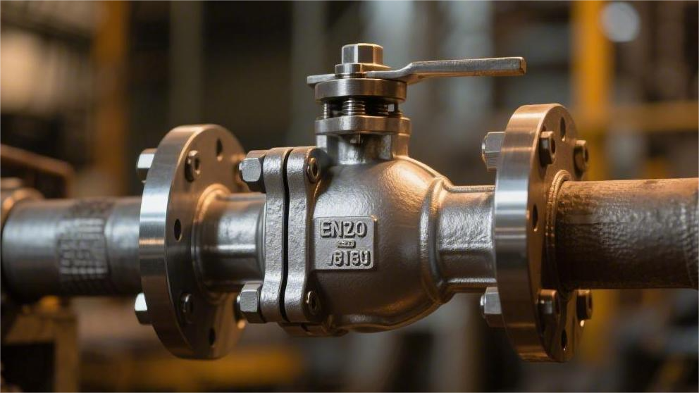
Sizes are customized from NPS 2 to 48; full port structure is mandatory if pigging operations are required; Pressure ratings strictly adapt from Class 150 to 2500; Applications with sour media must specify sulfur-resistant materials compliant with the NACE MR0175 standard. During factory acceptance, a hydrostatic test at 1.5 times the design pressure must be executed to verify safety. Size Conventional nominal pipe sizes (NPS) cover 2 to 60 inches. Selection requires distinguishing between Full Port and Reduced Port: the internal diameter of a full port matches the connected pipeline, with a pressure drop approaching 0 psi, allowing a Pig to pass through; A reduced port is typically reduced by 1 to 2 NPS sizes, reducing overall weight by 15% to 25%, suitable for non-pigging pipelines where a lower Cv value is acceptable. Pipe Diameter & Interfaces For sizes NPS 14 and above, the value equals the actual outside diameter (OD) of the pipe. For example, the OD of an NPS 16 pipe is fixed at 16.000 inches (406.4 mm). For sizes NPS 12 and below, the OD is larger than the nominal value; the OD of NPS 2 is actually 2.375 inches (60.3 mm). Pipe wall thickness schedules change the internal diameter, requiring the flow path of a trunnion-mounted ball valve to adapt synchronously. The wall thickness of an NPS 8 pipe under Sch 40 is 0.322 inches, with an internal diameter of 7.981 inches; when the operating pressure increases and Sch 160 is adopted, the wall thickness increases to 0.906 inches. At this time, the internal diameter shrinks to 6.813 inches. If a full port ball valve machined to Sch 40 is used, a 1.168-inch physical step will be created at the interface, causing fluid turbulence. The physical parameters of flange interfaces are divided into two size span intervals. Flange facings for NPS 2 to NPS 24 uniformly follow the ASME B16.5 specification. Taking an NPS 10 Class 300 flange as an example, its OD is 17.5 inches, thickness is 1.88 inches, with 16 evenly distributed bolt holes of 1.12 inches in diameter. The matching bolt circle (BC) diameter is fixed at 15.25 inches. Large-diameter valve flanges from NPS 26 to NPS 60 must switch to the ASME B16.47 specification. This specification is divided into Series A (derived from MSS SP-44) and Series B (derived from API 605). For NPS 36 Class 600, the Series A flange OD is 50.25 inches, requiring 28 bolts of 1.62 inches; the Series B flange OD is 47.75 inches, utilizing 32 bolts of 1.38 inches. Regarding the choice between Series A and Series B for large-diameter flanges, three parameter differences must be verified: For Raised Face (RF) flanges in Class 150 and Class 300, the raised height is 0.06 inches (1.6 mm). When the pressure rating rises to Class 400 and above, the raised height is required to increase to 0.25 inches (6.4 mm), coordinating with spiral wound gaskets (CG or CGI type) to achieve physical compression sealing. To cope with high-pressure environments from Class 900 to Class 2500, flange faces are often machined into Ring Type Joints (RTJ). The hardness of Type R octagonal or oval gaskets must be 15 to 20 HB (Brinell Hardness) lower than the flange groove face hardness. For NPS 12 Class 1500 RTJ flanges, the specification requires the use of R-57 metal ring gaskets; the ring groove depth must be precisely machined to 0.44 inches, and the groove bottom fillet radius is 0.06 inches. Butt Weld (BW) ends replace flanges in high-temperature, high-pressure pipelines, eliminating 0.1% of potential micro-leakage points. The geometry of the butt weld bevel is specified by ASME B16.25. When the pipe wall thickness (t) is between 0.19 inches and 0.88 inches, the end is machined to a 37.5°±2.5° single V-type bevel. A flat root face of 0.06 inches is retained to prevent the arc from burning through during root pass welding. When the pipe wall thickness exceeds 0.88 inches (22 mm), the bevel style changes to a Compound Bevel. The lower section of the bevel (within 0.75 inches from the root) maintains a 37.5° angle, while the upper section angle decreases to 10°. The compound bevel design can reduce weld metal fill volume by 20% to 30%, lowering welding residual stress and the probability of intergranular corrosion caused by the heat-affected zone (HAZ). When assembling butt-welded valves and pipelines, three end measurement data must be verified: The upper limits of the physical dimensions for interface types in actual pipe networks are distributed as follows in the table: Interface Type Standard Specification Nominal Pipe Size Range Maximum Pressure Class Adaptation Fastening/Connection Material Parameters Raised Face Flange (RF) ASME B16.5 NPS 2 – NPS 24 Class 600 ASTM A193 B7, min. yield 105 ksi Ring Type Joint (RTJ) ASME B16.47 NPS 26 – NPS 60 Class 2500 316SS ring gasket, max. hardness 160 HB Butt Weld End (BW) ASME B16.25 NPS 2 – NPS 60 Unlimited AWS ER70S wire matching pipe material “Two-holing” is the alignment guideline for heavy industrial pipeline laying. When the valve is on a horizontal pipeline, the centerline connecting the top two bolt holes on the flange face must be precisely horizontal, and the perpendicularity deviation must not exceed 0.5 degrees. No bolt hole can be located at the absolute top dead center, meaning a Straddle Centerline layout. The connection interface dimensions between the actuator and the valve stem are governed by the ISO 5211 standard. For an NPS 10 Class 300 trunnion-mounted ball valve, the stem output torque is often around 2500 Nm, requiring an ISO 5211 F16 flange plate. The F16 top flange has an OD of 210 mm, containing 4 M20 threaded holes distributed on a 165 mm pitch circle, and the stem extension length must reach 55 mm to match the scotch yoke actuator connection shaft. For NPS 2 and smaller vent or drain bypass ball valves, Socket Weld (SW) or NPT threaded interfaces are commonly used. ASME B16.11 specifies the socket depth for SW
How to Improve Trunnion Mounted Ball Valve Durability | Surface Treatment, Sealing Technology, Alloy Materials
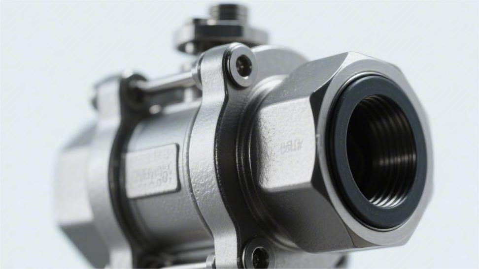
The sphere surface needs to be sprayed with tungsten carbide to a thickness of 0.05 mm, achieving a hardness exceeding 68 HRC to resist wear; The seal adopts a dual PEEK and metal structure, requiring regular maintenance by injecting grease through the injection valve; Under highly corrosive conditions, core internal components should be directly replaced with Duplex Steel 2205 or Inconel alloy. Surface Treatment The engineering industry typically uses HVOF (High Velocity Oxygen Fuel) spraying to deposit a 150 to 250-micrometer thick tungsten carbide layer, achieving a surface hardness of 1000 to 1400 HV0.3 and controlling porosity below 1%. For NACE MR0175 sour service conditions containing hydrogen sulfide (H2S), a 75-micrometer thick Electroless Nickel Plating (ENP) layer with 10-12% phosphorus content is often applied to block media erosion. For high-temperature fluids above 500°C, a Stellite cobalt-based alloy thicker than 3 millimeters is applied via Plasma Transferred Arc (PTA) welding to maintain metal red hardness. HVOF Supersonic Spraying The pressure inside the combustion chamber is usually maintained between 0.6 and 1.0 MPa. The mixed gas expands and accelerates through a Laval nozzle. The final exit velocity of the airflow can exceed Mach 2.0, reaching 1500 to 2000 meters per second. Powder particles carried in the supersonic airflow are heated to a semi-molten state between 1600°C and 2500°C within milliseconds. Upon high-speed impact with the substrate surface, the kinetic energy of a single tungsten carbide powder particle usually exceeds 1.5 microjoules. The semi-molten particles undergo severe plastic deformation at the moment of impact. Engineers usually select 15 to 45-micrometer or 20 to 53-micrometer spherical agglomerated sintered powders. The tungsten carbide grain size within the powder needs to be controlled between 0.2 and 1.0 micrometers. Finer primary grains provide higher microhardness and reduce microscopic brittle spalling when subjected to solid particle impacts in the fluid. An excessively high feed rate causes uneven particle heating, increasing internal porosity to over 2%. API 6D ball valve standards require porosity to be strictly controlled within 0.5% to 1.0%. Extremely low porosity cuts off the physical path for fluid media to penetrate into the 316 or 17-4PH stainless steel substrate. Commonly used coating formulations fall into two major camps: tungsten carbide and chromium carbide. In sand-containing crude oil pipelines below 400°C, 86WC-10Co-4Cr is the most common formulation. The 10% cobalt provides toughness, and the 4% chromium enhances resistance to chloride ion erosion. When the system operating temperature rises to the 400°C to 850°C range, tungsten carbide undergoes a decarburization reaction, generating a brittle W2C phase. High-temperature environments exceeding 400°C require switching the coating material to a 75Cr3C2-25NiCr formulation. Chromium carbide-nickel chromium coatings exhibit an extremely low oxidation weight gain rate in 800°C thermal cycling tests. Substrate surface pretreatment is also a standardized operation. Prior to spraying, dry sandblasting using 24 to 60 mesh aluminum oxide grit must be performed. The surface roughness of the sphere after sandblasting needs to reach Ra 3.0 to 6.0 micrometers, providing sufficient anchor profile depth for subsequent mechanical interlocking. The spraying operation is usually completed in multiple passes, with a single-pass coating thickness controlled between 15 and 25 micrometers. The total accumulated thickness ranges from 150 to 250 micrometers. A coating thickness exceeding 300 micrometers causes a sharp increase in internal residual compressive stress, inducing macroscopic cracking. The surface of a freshly sprayed sphere is very rough and cannot meet Class V or Class VI leakage rate standards. Subsequent precision grinding taking hours to dozens of hours is required. Spherical external cylindrical grinding is performed using a 400 to 1000 grit diamond grinding wheel. After removing approximately 50 micrometers of allowance, the sphere dimensions return to the design tolerance range. After grinding, diamond lapping paste must be used to lap the sphere against a matching metal seat. The lapping process eliminates macroscopic waviness, creating a 100% perfect contact band on the sealing surface. The final sealing surface roughness Ra reaches 0.05 to 0.1 micrometers, achieving mirror-level optical flatness. In the Alberta oil sands projects in Canada, the medium contains up to 15% quartz sand particles. The local fluid velocity passing through a reduced-bore ball valve can reach 15 m/s. Untreated A105 carbon steel ball valves suffer severe internal leakage due to erosion grooving after just 300 hours of operation. Ball valves utilizing a 200-micrometer 86WC-10Co-4Cr coating operate fault-free for over 8000 hours under the exact same conditions. When high-speed solid particles strike the coating surface at angles of 30 to 90 degrees, the hard tungsten carbide grains resist micro-cutting forces. The cobalt-chromium alloy matrix acting as a binder absorbs the impact kinetic energy, delaying the propagation of fatigue cracks. ASTM G76 erosion wear test data indicates that under a 90-degree angle impact, the erosion rate of this coating is only 0.02 mm³/g. ENP Electroless Nickel Plating The autocatalytic deposition reaction using sodium hypophosphite as a reducing agent takes place in a weak acidic aqueous solution at 85°C to 92°C. The pH value of the bath is strictly controlled between 4.5 and 5.0. Nickel ions are continuously reduced without applying electrical current and uniformly cover the geometric surface of the carbon steel or low-alloy steel sphere. Complex topographies such as the root of flanges, the inner wall of the sphere flow passage, and the undercut of the fixed trunnion all achieve an coating of equal thickness. The deposition rate is usually maintained at 10 to 15 micrometers per hour. The edge thickening phenomenon caused by the Faraday electroplating effect is eliminated, and the profile tolerance of the sphere’s outer diameter can be controlled within ±2 micrometers. Industrial valves commonly use a high-phosphorus formulation with a phosphorus mass fraction of 10% to 14%. After the liquid metal deposition cools, it presents an amorphous microstructure without grain boundaries. Physical channels for intergranular corrosion are blocked, and the chloride ion permeation rate is less than 0.01 mm/year under a 50 MPa differential pressure. According to the ASTM B733 standard specification, a high-phosphorus coating is considered to be in a pore-free state when the deposition thickness
How to Choose a Trunnion Mounted Ball Valve for Industrial Pipelines | Pressure Rating, Body Material, End Connection
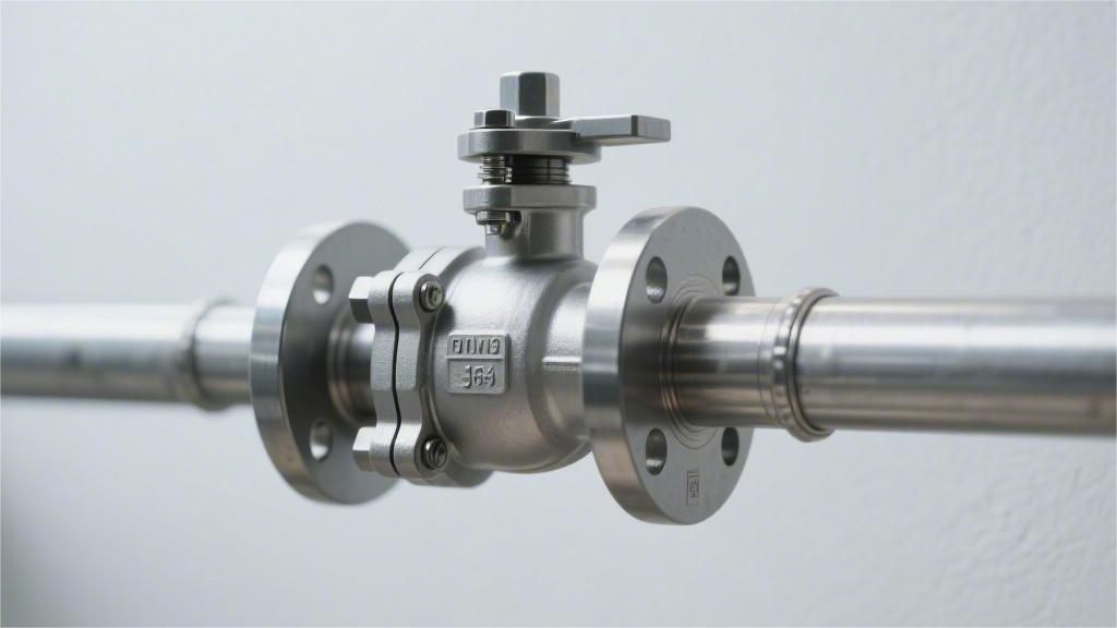
Pressure ratings are typically selected between Class 150 and 2500; Conventional body material is WCB carbon steel, while CF8M stainless steel is specified for corrosive media; BW (Butt Weld) ends are recommended for high pressure, and RF (Raised Face) flanges for low pressure. During installation and mating, flange bolts must be tightened in a diagonal sequence to ensure a leak-free seal. Pressure Rating In the ASME B16.34 standard, the pressure rating distribution for trunnion mounted ball valves ranges from Class 150 to Class 2500. Taking the common ASTM A105 carbon steel material as an example, a Class 600 valve can withstand 1480 psi of pressure at 38°C; when the temperature rises to 427°C, the allowable pressure drops to 675 psi. When selecting equipment, the piping design pressure must be added with a margin of at least 10%, and strictly compared against the P-T (Pressure-Temperature) rating charts to confirm that the valve rating aligns with the engineering parameters of the flanges and line pipes (e.g., API 5L X65). ASME vs API ASME B16.34 originates from the Boiler and Pressure Vessel Code and is a broad foundational document covering various industrial pressure-bearing valves from Class 150 to Class 4500. API 6D is compiled by the American Petroleum Institute, specifically customized for long-distance oil and gas pipelines. Its scope of application is limited to a maximum of Class 2500, and it adds specific physical data and testing requirements unique to long-distance pipelines on top of ASME’s base parameters. Taking a 24-inch Class 600 trunnion mounted full bore ball valve as an example, API 6D explicitly specifies that its minimum internal diameter must reach 590 mm (23.25 inches). This dimensional tolerance is set to allow smart pigs inside the pipeline to pass through the valve cavity without obstruction. In contrast, ASME B16.34 only specifies the connection dimensional parameters for the flanges at both ends of the valve body, and does not establish mandatory physical data lower limits for the degree of bore reduction inside the valve cavity. There are differences in the basis for calculating the metal wall thickness of the pressure-bearing shell. According to the appendix specifications of ASME B16.34, the actual measured wall thickness of a 12-inch Class 600 carbon steel (ASTM A105) forged valve body must not be less than 18.3 mm. Specification Comparison Item ASME B16.34 Requirements API 6D Requirements Pipeline Pigging Capability No specific requirements, standard reduced bore allowed Must provide Full Bore option Minimum Internal Diameter Determined by manufacturer’s independent design Appendix Table C provides the baseline internal diameter accurate to the millimeter Base Wall Thickness Calculated based on temperature and pressure ratings Adopts ASME data and typically adds a 3.2 mm corrosion allowance End Bevel Complies with ASME B16.25 standard Mandatorily complies with B31.4 or B31.8 specifications for long-distance pipelines For the pressure testing phase before valves leave the factory, API 6D sets a longer standard for pressure holding time. For valves with a nominal diameter of 10 inches or greater, the minimum holding time for the hydrostatic Shell Test required by ASME B16.34 is only 2 minutes. Under the same 10-inch physical specifications, API 6D mandates that the holding time for the shell test be extended to 5 minutes. Engineers must use a chart recorder to capture the pressure decay curve at 1.5 times the rated cold working pressure and sign the test certificate. The medium and pressure parameters for the Seat Test are completely different. The ASME specification allows routine testing using only water at 1.1 times the working pressure, whereas API 6D compulsorily adds a low-pressure gas testing phase. Factory inspectors need to inject compressed air or nitrogen at 80 psi (approx. 0.55 MPa) into the valve cavity. Within a 2-minute holding period, according to the ISO 5208 standard, the leakage rate of a soft-seated trunnion mounted ball valve must achieve Rate A, i.e., 0 drops/minute. Double Block and Bleed (DBB) functionality is a proprietary technical indicator for long-distance pipeline valves. API 6D clearly defines DBB as well as Double Isolation and Bleed (DIB-1 and DIB-2) physical testing protocols in separate sections. According to API’s DBB testing procedures, water pressure is injected into the cavity and raised to 1.33 times the rated pressure. When the internal cavity pressure exceeds the spring preload force due to fluid thermal expansion, the Single Piston Effect (SPE) seats will automatically relieve pressure to both ends of the pipeline. The opening pressure data when the relief action occurs must be recorded by high-frequency sensors, usually safely set between a differential pressure of 100 psi and 300 psi. The ASME B16.34 standard text completely lacks functional definitions regarding bi-directional sealing and middle cavity pressure relief such as DBB or DIB. Ultra-high pressure oil and gas wellhead operating conditions will deviate from the API 6D standard and instead adopt the higher-tier API 6A specification. API 6A uses psi as the basic rating unit, covering 2000 psi, 5000 psi up to the ultra-high pressure 20000 psi level. API 6A introduces the gradient concept of Product Specification Levels (PSL 1 to PSL 4). Under the PSL 3G level, trunnion mounted ball valves must undergo extreme nitrogen micro-leakage testing at full rated working pressure (e.g., 10000 psi). The Non-Destructive Testing (NDT) coverage for metal materials increases exponentially as the PSL rating rises. PSL 3 requires 100% Ultrasonic Testing (UT) and Magnetic Particle Testing (MT) on all pressure-bearing forgings, and the retention of radiographic films for 10 years. Conventional industrial water line valves under ASME specifications usually only conduct proportional sampling of materials according to the ASTM A388 standard. Only when the buyer provides additional Material Data Sheets (MDS) will ordinary ASME valves undergo full 100% flaw detection. Traceability and Testing Documents Conventional ASME Order Standards API Pipeline Project Standards Material Test Reports EN 10204 2.2 Declaration of Compliance EN 10204 3.1 or 3.2 Physical and Chemical Report Nameplate Identification Requirements Laser-etched basic parameters Must bear the official API Monogram Operating Torque Data Theoretical calculated values Breakaway torque must be actually measured at full
What’s the Difference Between Soft Seat and Metal Seat Side Entry Ball Valves | Temperature Range, Sealing Performance, Wear Resistance
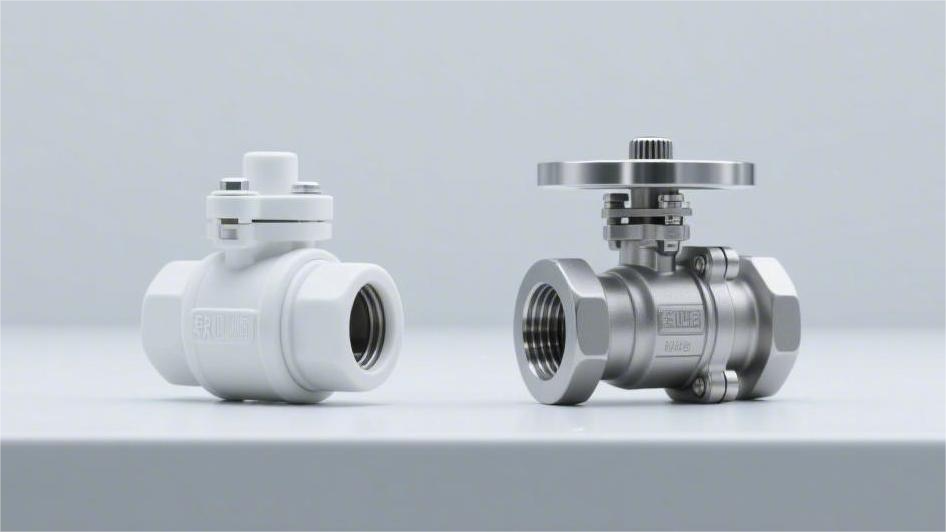
Soft-seated side-entry ball valves (such as PTFE) are suitable for temperatures below 200°C and can achieve Class VI zero leakage, but they have poor wear resistance. The pipeline must be purged before operation to prevent particles from scratching the valve seat. Metal-seated valves (such as those with tungsten carbide coatings) can withstand high temperatures up to 500°C and are extremely wear-resistant. They are specifically designed for media containing solid impurities, but typically only meet the Class IV standard for micro-leakage. Temperature Range The operating temperature of soft-seated side-entry ball valves (PTFE, PEEK, etc.) generally ranges from -40°C to 260°C. Exceeding 260°C will cause polymer materials to soften and undergo permanent plastic deformation. The coefficient of thermal expansion for soft sealing materials is about 10 times that of metals. Metal hard-seated ball valves have a conventional range of -196°C to 427°C; If the rear spring is replaced with Inconel 718 and full graphite gaskets are used, the maximum operating temperature can be extended to 538°C or even 815°C. This relies primarily on mechanical springs to real-time compensate for physical displacements caused by thermal expansion and contraction. Soft Sealing The molecular chain of pure polytetrafluoroethylene (PTFE) is composed of carbon-fluorine bonds, resulting in a friction coefficient of only 0.04. This extremely low frictional resistance allows the operating torque of an ASME Class 150 6-inch ball valve to be kept under 150 N·m. When the internal system pressure exceeds the yield strength of the polymer, the material experiences a creep phenomenon. Under an ambient temperature of 20°C and a continuously applied pressure of 15 MPa, a pure PTFE seat will exhibit approximately 4% radial deformation within 48 hours. The ball pushes against the seat under pressure, and exceeding the elastic recovery limit will result in permanent dimensional reduction. To suppress physical deformation, manufacturers usually dope the base material with 15% to 25% chopped glass fibers or carbon fibers to create reinforced polytetrafluoroethylene (RTFE). After doping, the tensile strength of the material increases from 14 MPa to 25 MPa, and the heat deflection temperature is raised by about 40°C. RTFE containing 25% carbon fiber sees its thermal conductivity increase to 0.45 W/(m·K). Natural gas pipeline transportation conditions frequently use polyamides (Nylon 12 or Devlon V-API) as seals. The Rockwell hardness of Devlon V-API reaches R112, allowing it to withstand extreme pipeline pressures up to 137 MPa. Its water absorption rate is exceptionally low, with a weight increase of less than 0.1% after soaking in 23°C water for 24 hours. In high-pressure natural gas systems, gas molecules penetrate the microscopic pores of the polymer. When an emergency pipeline blowdown occurs, and the system pressure drops precipitously from 100 bar to atmospheric pressure in seconds, the expansion stress inside the polymer can reach hundreds of megapascals. Anti-Explosive Decompression (AED) testing requires that the cross-sectional crack length of the material after undergoing a depressurization cycle must not exceed 5% of the total packing thickness. Polyetheretherketone (PEEK) exhibits extremely high yield strength in harsh chemical environments and high temperatures. Even in a 200°C environment, its tensile strength remains above 50 MPa. PEEK seats typically use a floating design with O-rings paired with Belleville springs, requiring an initial preload equivalent to 1.2 times the projected area of the seat. In sour gas field environments with high concentrations of hydrogen sulfide (H2S), soft sealing components must comply with the NACE MR0175/ISO 15156 standard. Fluoroelastomer (FKM) O-rings are prone to cross-linking and hardening when exposed to H2S concentrations exceeding 10%; their Shore hardness can surge from 75A to over 90A within 168 hours. The assembly between the seat insert and the metal support ring utilizes an interference fit process to achieve initial bi-directional sealing. The assembly tolerances are strictly controlled, reflecting as follows: API 607 fire-safe testing requires side-entry ball valves to maintain cutoff capability after being baked by a 750°C to 1000°C flame for 30 minutes. Polymer seats completely burn and vaporize at around 350°C. Driven by pipeline pressure, the ball subsequently moves downstream and presses tightly against the machined step on the metal valve body. The secondary metal sealing band after the fire must meet strict testing specifications for extremely low leakage rates: The friction coefficient of polymer materials exhibits a non-linear increase over time and with changes in system pressure. For a ball valve that has remained closed for an extended period, the starting torque may increase by 30% to 50% compared to its initial value because the polymer plastically embeds into the ball’s microscopic surface. The safety factor for selecting a pneumatic actuator must usually be set at 1.25 to 1.5. Solid particulates entrained in the pipeline with a diameter greater than 50 microns easily embed into the softer PTFE surface. Under the high-speed scouring of fluids, fine grit will plow scratches 0.1 to 0.5 mm deep into the polymer surface. In gas conditions with a differential pressure of 10 bar, even minuscule scratches can trigger a leak exceeding 500 standard cubic centimeters per minute. The Double Block and Bleed (DBB) function relies on the self-relieving design of the soft sealing components to prevent abnormal pressure buildup in the middle cavity. The mechanical action of the relief path is as follows: Polychlorotrifluoroethylene (PCTFE) is commonly used in cryogenic control segments of LNG receiving terminals. The shrinkage rate of this material at -196°C approaches 2.5%; engineered solutions offset this volume reduction by installing a wave spring at the rear with a pre-compression of 3 to 5 mm. Cryogenic sealing tests require filling with helium gas and detecting with a mass spectrometer, where the leakage rate must be less than 1.0×10^-4 mbar·L/s. Metal Hard Sealing The seat base material of metal hard-seated ball valves typically uses ASTM A105 forged steel or F316 stainless steel to cope with ASME Class 900 and higher high-pressure pipelines. To resist fluid erosion, a layer of tungsten carbide coating between 0.15 and 0.3 millimeters thick is applied to the substrate surface via the High-Velocity Oxygen Fuel (HVOF) process. The spray velocity of the
How to Select Materials for Custom Side Entry Ball Valves | Carbon Steel, Stainless Steel, Duplex Steel
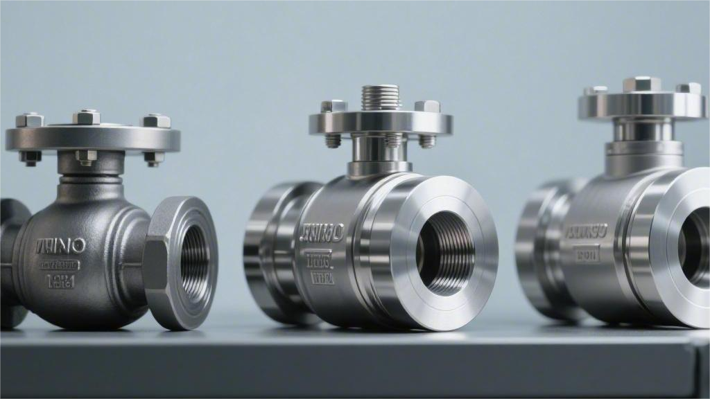
Carbon steel (WCB) is suitable for water and oil at temperatures from -29 to 425°C; Stainless steel (316) resists strong acids and withstands high temperatures up to 600°C; Duplex steel (2205) features a Pitting Resistance Equivalent Number (PREN) > 32, specializing in high-chloride environments. Carbon Steel WCB cast steel and A105 forged steel provide a minimum yield strength of 250 MPa in the temperature range of -29°C to 425°C. In crude oil, natural gas, or industrial water pipelines, the material cost of carbon steel valve bodies is 30% to 40% of that of 316 stainless steel. Under flange ratings ranging from Class 150 to Class 2500, carbon steel shells can withstand system pressures up to 414 bar. To prevent rusting, the internal components of carbon steel ball valves are often treated with a 75-micron thick ENP (Electroless Nickel Plating), while the exterior is sprayed with an epoxy resin coating with a dry film thickness of no less than 200 microns. Casting & Forging The body forming processes for side-entry ball valves are divided into two major categories: casting and forging, with manufacturing standards based on ASME B16.34. When determining the forming route for the outer shell metal, manufacturers must calculate the matching degree between the valve’s Nominal Pipe Size (NPS) and pressure rating (Class). The casting process involves injecting liquid metal heated above 1600°C into a sand mold or precision investment mold to cool and form. The wall thickness of ASTM A216 WCB carbon steel castings is typically increased by 10% to 15% compared to forgings of the same specification to compensate for potential internal micro-shrinkage or porosity defects. The forging process utilizes a hydraulic press to apply tens of thousands of tons of mechanical pressure to a solid metal blank, causing plastic deformation within the die cavity. The internal grain structure of the metal forms a continuous streamline distribution along the valve body contour, and the mechanical density of ASTM A105 forged steel is approximately 8% higher than that of cast steel. Nominal Pipe Size and pressure rating together define the economic watershed for the forming process. For high-pressure side-entry ball valves ranging from 2 inches to 10 inches with pressure ratings from Class 900 to Class 2500, industry standards mandate the use of multi-piece forged shells. The ASME B16.34 standard specifies entirely different Non-Destructive Testing (NDT) acceptance levels for the outer shells produced by these two forming processes. The proportion of testing costs relative to the total manufacturing cost of the valve body fluctuates based on changes in diameter and material density. Forming Process Primary NDT Methods ASME Reference Standard Defect Tolerance Data Testing Cost Proportion Sand Casting Radiographic Testing (RT) + Magnetic Particle Testing (MT) ASME BPVC Section V Article 2 Allows Level 2 porosity, max diameter not exceeding 1.5 mm 15% – 20% Investment Casting Penetrant Testing (PT) + Radiographic Testing (RT) ASTM E446 Allows trace shrinkage, surface roughness Ra 3.2 – 6.3 10% – 15% Open-die Forging Ultrasonic Testing (UT) ASTM A388 Zero volumetric defects, no equivalent reflection wave exceeding 2 mm allowed 5% – 8% Closed-die Forging Ultrasonic Testing (UT) + Magnetic Particle Testing (MT) ASME BPVC Section VIII Zero cracks, surface flake detection rate must be controlled at 0% 3% – 5% During radiographic testing of cast valve bodies, if sand inclusion defects with a cross-sectional area greater than 25 square millimeters are discovered in the center of the wall thickness, back gouging and repair welding are required. According to ASME BPVC Section IX, the Post-Weld Heat Treatment (PWHT) temperature must be maintained between 600 and 650°C, with the holding time calculated at 1 hour per inch of wall thickness. Because forged valve bodies do not experience phase transformation stresses during liquid solidification, their fatigue life exhibits high consistency in cyclic opening tests. In -196°C Liquefied Natural Gas (LNG) pipelines, ASTM A350 LF2 forgings show a valve body deformation rate of less than 0.01 mm after 500,000 full differential pressure open-close cycles. The setting of machining allowances is closely related to the dimensional accuracy of the original forming process. The tolerance range for castings is affected by the thermal expansion coefficient of the mold, usually executing according to the ISO 8062 CT10 grade, with a single-side machining allowance needing to reserve 6 to 10 millimeters. The external dimensions of forgings are closer to the final drawing contour, with tolerances controlled within the ISO 8062 CT8 grade. When using Computer Numerical Control (CNC) machine tools to process the flange sealing surfaces of side-entry valves, the single-side cutting amount for forgings is only 3 to 5 millimeters, and the cutting tool wear rate is reduced by approximately 40% compared to machining castings containing sand cores. Differences in the manufacturing cycle are subject to the dual constraints of mold development and material procurement. Sand mold preparation and pouring cooling for large-diameter wooden pattern casting typically consume 6 to 8 weeks. Standard-sized open-die forged round bars or rolled rings are available in stock at large steel mills, so cutting and rough machining only require 2 to 3 weeks. The unit price of materials in project procurement lists fluctuates with the international bulk commodity market. When utilizing duplex stainless steel, the procurement cost per unit weight for forged materials is 45% to 60% higher than that of castings. The upper limit for carbon content in ASTM A105 forgings per metallurgical specifications is set at 0.35%, and manganese content reaches up to 1.05%. The refined proportion of chemical elements, following a 900°C normalizing heat treatment, can produce a uniform pearlite and ferrite microstructure. The phosphorus and sulfur impurity contents in ASTM A216 WCB cast steel are strictly limited to below 0.04% and 0.045%, respectively. When liquid metal solidifies in a sand mold, the cooling rate difference in the wall thickness transition area is 10 to 15°C per second, which easily generates residual thermal stress. The stress-relief annealing process after forming is a prerequisite for ensuring the dimensional stability of side-entry ball valves during long-term service. The heating rate
How to Improve Side Entry Ball Valve Reliability in Pipelines | Sealing System, Stem Design, Corrosion Protection
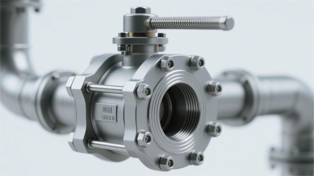
The seal utilizes a PEEK bi-directional valve seat resistant to high temperatures up to 260°C to ensure zero leakage; The stem features an anti-blowout stepped design and is equipped with multi-stage O-rings to prevent leakage; The surfaces of core components undergo 50-micron-thick Electroless Nickel Plating (ENP) or Inconel alloy weld overlay for corrosion resistance, which, combined with regular grease injection maintenance, can ensure the long-term safe operation of the pipeline. Sealing System Under Class 1500 (25.5 MPa) operating conditions, valves meeting the ISO 5208 Rate A standard must maintain no visible bubbles for 3 minutes during a full-pressure test. Adopting Polyether Ether Ketone (PEEK) combined with a Double Isolation and Bleed (DIB) structure can maintain 50,000 opening and closing cycles in 200°C and 5% H2S media. During selection, engineers equipping the valve with a combination of Anti-Explosive Decompression (AED) rubber and API 6FA fire-safe metal lip seals can reduce the unplanned downtime rate by 40%. Materials & Temperature The molecular chain of virgin Polytetrafluoroethylene (PTFE) remains stable in the range of -50°C to 200°C. Virgin PTFE will experience cold flow deformation under 10 MPa pressure; in industrial manufacturing, 15% to 25% of glass fiber or carbon powder is usually blended in for physical reinforcement. Reinforced PTFE (RTFE) raises the material’s compressive yield threshold to 15 MPa. On offshore oil production platforms in the Gulf of Mexico, RTFE valve seats can withstand 10,000 continuous opening and closing cycles without plastic extrusion in 150°C crude oil media. Polyamide (Nylon) provides higher mechanical tensile strength, with test values reaching 70-90 MPa. Nylon 12 has a water absorption rate of less than 0.1%, maintaining absolute dimensional stability over the long term in 120°C Class 900 (15.3 MPa) natural gas pipeline networks. Polyether Ether Ketone (PEEK) can operate continuously at high temperatures of 260°C, with a tensile strength exceeding 100 MPa. In Class 1500 (25.5 MPa) high-pressure gas injection wells, PEEK material exhibits extremely high resistance to rapid gas decompression. Polymer Material Name Tensile Strength (MPa) Maximum Continuous Operating Temperature Applicable Maximum Pressure Class Virgin PTFE 20 – 30 200°C Class 600 (10.2 MPa) Reinforced PTFE (RTFE) 25 – 35 200°C Class 900 (15.3 MPa) Polyamide 12 (Nylon 12) 70 – 90 120°C Class 900 (15.3 MPa) Polyether Ether Ketone (PEEK) 100 – 110 260°C Class 2500 (42.5 MPa) Polychlorotrifluoroethylene (PCTFE) 30 – 40 120°C (Common for cryogenic) Class 1500 (25.5 MPa) Liquefied Natural Gas (LNG) receiving terminals in Qatar handle ultra-low temperature fluids at -162°C. Ordinary polymer materials become brittle in extreme cold; Polychlorotrifluoroethylene (PCTFE/Kel-F) is widely applied because it still possesses a compressive strength of 35 MPa at -196°C. When fluids contain quartz sand or pipeline iron oxide scale, the surfaces of polymer soft materials will be rapidly scratched. The system structure shifts to metal-to-metal physical contact, and a hardened layer is applied to the surface through the High-Velocity Oxygen Fuel (HVOF) thermal spray process. Tungsten Carbide (WC) particles impact the ball and seat surfaces at a speed of 800 meters/second, forming a dense coating with a thickness of 0.15 mm to 0.3 mm. The surface Rockwell hardness reaches 70-75 HRC, capable of resisting severe abrasive wear in Class 2500 slurry pipelines. Chromium Carbide (Cr3C2) coatings maintain physical and chemical stability in oxidizing environments up to 815°C. In high-temperature delayed coking units, a 0.2 mm thick coating prevents the metal galling of 316 stainless steel balls and seats during thermal expansion. Metal Hardening Coating Typical Spraying Process Surface Hardness Maximum Operating Temperature Tungsten Carbide HVOF (High-Velocity Oxygen Fuel) 70 – 75 HRC 400°C Chromium Carbide HVOF (High-Velocity Oxygen Fuel) 65 – 70 HRC 815°C Stellite 6 PTA (Plasma Transferred Arc) 40 – 45 HRC 600°C Electroless Nickel Plating (ENP) Chemical Deposition 50 – 55 HRC 300°C The static gap between the metal seat ring and the valve body is sealed using elastomer O-rings. The Norwegian Norsok M-710 specification outlines testing procedures for the explosive decompression resistance of rubber materials in high-pressure CO2 or H2S environments. Fluoroelastomer (FKM/Viton) provides chemical corrosion resistance up to 200°C. Standard 75 Shore A FKM will blister and rupture under a 10 MPa pressure drop; Anti-Explosive Decompression (AED) grade FKM increases the hardness to 90 Shore A to resist volume expansion. The lower working temperature limit of Hydrogenated Nitrile Butadiene Rubber (HNBR) reaches -40°C, while also possessing the physical properties to resist sour gas (H2S) attack. Winter pipelines in Alberta, Canada use HNBR O-rings paired with PTFE backup rings to prevent extrusion damage under 15 MPa pressure. Perfluoroelastomer (FFKM/Kalrez) can withstand highly aggressive amine desulfurization solvents and temperatures up to 327°C. Its procurement cost is 50 times that of conventional FKM, and it is usually only deployed in offshore sour gas reinjection manifolds. When the ambient temperature breaches the 327°C upper limit or falls below the -50°C lower limit, polymer elastomers completely lose their resilience. Elgiloy alloy springs encased in Inconel 718 U-shaped jackets become the alternative, maintaining a radial contact load of 25 N/mm against the valve body sidewall. The NACE MR0175/ISO 15156 specification restricts the metallurgical parameters of metal pressure-bearing components in sour environments. Valve bodies forged from ASTM A350 LF2 carbon steel are mandatorily required to have a Rockwell hardness controlled below 22 HRC to prevent sulfide stress cracking. Subsea manifolds at a depth of 3000 meters withstand external seawater hydrostatic pressure up to 30 MPa. The internal PEEK seats and the external Inconel 625 weld overlay of the valve body form a double physical barrier, isolating the internal corrosive fluid from the 4°C deep-sea environment. The stuffing box in the stem area utilizes molded expanded graphite rings. The physical density of the graphite rings is compressed to 1.6 g/cm³, and mechanical stress is applied via a stainless steel packing gland to seal Volatile Organic Compound (VOC) fugitive emissions below 100 ppm. Live-loaded Belleville springs are installed in series on the packing gland bolts to compensate for the microscopic volumetric shrinkage of the graphite during thermal cycling. Four pairs of 17-7 PH stainless steel spring
What’s the Difference Between Forged and Cast Side Entry Ball Valves | Strength, Pressure Capacity, Durability
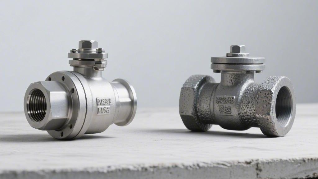
Forged steel side-entry ball valves are forged under high pressure, resulting in a dense internal structure without porosity, extremely high strength, the ability to withstand high pressures of Class 2500 (approximately 42 MPa) and above, and exceptional durability. Cast steel ball valves are formed by pouring molten steel. They are prone to internal shrinkage cavities and generally have a pressure rating below Class 900, but they are suitable for large-diameter, low-cost manufacturing. In practical selection and operation, if the pipeline pressure exceeds 10 MPa or the medium is flammable and explosive, forged steel valves must be selected to prevent leakage and rupture. Strength Forged side-entry ball valves (such as ASTM A105) undergo mechanical extrusion to reshape metal grains and form directional flow lines, resulting in an internal porosity of close to 0%. Their standard yield strength reaches over 250 MPa, and tensile strength exceeds 485 MPa. Cast ball valves (such as ASTM A216 WCB) are formed by the solidification of liquid metal, with isotropic grains and a yield strength of approximately 205 MPa. When subjected to system pressures exceeding 2000 psi or cryogenic environments of -196°C, forgings have no shrinkage cavities or micro-crack defects. The energy absorption value in the Charpy V-notch test is typically 20% to 30% higher than that of castings made of the same material. Comparison of Mechanical Parameters A material tensile testing machine stretches a standard circular metal specimen with a cross-sectional area of 0.2 square inches at a fixed rate. The test instrument accurately records the tensile force value when the material undergoes a 0.2% permanent plastic deformation. This data indicator is marked as the minimum yield strength on engineering physics drawings. The minimum yield strength of forged carbon steel ASTM A105 at a normal temperature of 20°C is calibrated at 250 MPa. Under the same environment, the lower yield limit parameter of cast carbon steel ASTM A216 WCB is 205 MPa. ASME B16.34 sets entirely different valve body wall thickness calculation multipliers based on this 45 MPa physical stress difference. After exceeding the yield point extremum, the metal material enters the plastic deformation zone until it is stretched and fractured. The highest tensile force recorded by the testing machine during this physical stage divided by the original cross-sectional area yields the tensile strength indicator. Carbon steels formed by the two manufacturing processes are subject to identical numerical specifications for their baseline tensile strength parameters. Carbon Steel Mechanical Test Items (ASTM A370) Forged ASTM A105 Cast ASTM A216 WCB Minimum Yield Strength (0.2% offset) ≥ 250 MPa (36,000 psi) ≥ 205 MPa (30,000 psi) Tensile Strength Limit Range 485 – 655 MPa (70-95 ksi) 485 – 655 MPa (70-95 ksi) Axial Elongation (50mm Gauge Length) ≥ 22% ≥ 22% Reduction of Area at Fracture ≥ 30% ≥ 35% The reduction of area reflects the lateral physical deformation capacity of a metal material before it is completely pulled apart. The displacement sensor of the universal testing machine shows that the radial shrinkage deformation of the A105 specimen before fracture is slightly smaller than that of WCB. The high-density directional microscopic metal flow lines forcibly constrain the physical slip of the material on the radial cross-section. For pipeline fluid systems in -46°C cryogenic environments, the pipeline material grades are required by regulations to switch to ASTM A350 LF2 forgings and ASTM A352 LCC castings. Metal steels with low carbon content will undergo a complete physical ductile-to-brittle transition in sub-zero low-temperature environments. The Charpy V-notch pendulum impact test quantifies the fracture absorbed energy parameter of the material in extreme cold conditions. A standard solid metal specimen measuring 10mm x 10mm x 55mm is placed in an industrial cooling bath and forcibly cooled to -46°C. A test hammer of the 300-joule magnitude physically strikes the back of the specimen notch at an initial velocity exceeding 5 meters per second. The test instrument panel digitally outputs the physical energy in joules consumed during the fracture of the specimen. When petrochemical pipeline systems transport highly corrosive industrial media, austenitic stainless steel is usually specified. Both ASTM A182 F316 forgings and ASTM A351 CF8M castings contain 16% to 18% chromium and 10% to 14% nickel metal elements. The same austenitic metal matrix exhibits obvious physical differentiation in lattice density under the intervention of different forming physical pressures. The multi-million-ton physical compressive stress of the forging machine tool completely eliminates the dendritic segregation phenomenon caused by liquid cooling and solidification. Under the same geometric volume, F316 stainless steel exhibits higher macro-structural pressure-bearing rigidity than CF8M. Comparison of Stainless Steel Mechanical Indicators Forged ASTM A182 F316 Cast ASTM A351 CF8M Normal Temp Baseline Yield Strength ≥ 205 MPa (30,000 psi) ≥ 205 MPa (30,000 psi) Minimum Tensile Strength Requirement ≥ 515 MPa (75,000 psi) ≥ 485 MPa (70,000 psi) Axial Elongation (50mm Gauge Length) ≥ 30% ≥ 30% Factory Brinell Hardness Upper Limit ≤ 187 HBW No mandatory upper limit quantification spec The baseline tensile strength parameter of A182 F316 is forcibly pulled up by 30 MPa by industrial specifications. The high-pressure fluid inside the pipeline continuously exerts an outward radial physical thrust on the valve’s metal wall. According to Barlow’s wall thickness calculation formula, in a cylindrical pressure-bearing shell with consistent wall thickness data, an increase in tensile strength proportionally amplifies the overall burst safety pressure margin of the pipeline. Metal hardness testing does not destroy the internal physical structure of the side-entry ball valve and is widely used for batch sampling on production lines. A standard indenter made of hard alloy is pressed into the metal surface under a vertical physical pressure of 3000 kilogram-force (kgf). An industrial measuring microscope accurately reads the diameter of the indentation on the metal surface and logarithmically converts it into a standard Brinell hardness value. In the daily 90-degree opening and closing rotation test cycles of ball valve equipment, high-intensity physical friction occurs between the surface of the metal ball and the valve seat seal ring. The absolute surface hardness indicator of the pressure-bearing metal
How to Choose a Side Entry Ball Valve for Industrial Pipelines | Pressure Rating, Body Material, End Connection
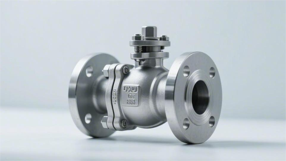
First, determine the pressure rating, selecting from Class 150 to 2500 based on the operating conditions; Second, determine the material, conventionally using WCB carbon steel, and CF8M stainless steel for corrosive media; ly, select the end connection, utilizing RF flanges for low pressure, and BW butt-welding for high pressure to prevent leakage. Pressure Rating According to the ASME B16.34 standard, common ratings are classified from Class 150 to Class 2500. Taking a Class 300 WCB carbon steel valve as an example, the maximum allowable working pressure at 38°C is 740 psi. When the temperature rises to 427°C, the pressure-bearing capacity drops to 410 psi. We need to combine and compare the dual P-T (Pressure-Temperature) ratings of the metal valve body and the internal soft sealing materials (such as PTFE, PEEK), and reserve a 10% physical safety margin to select the specific Class value. Pressure-Temperature Derating In the ASME B16.34 specification, the yield strength of metal materials exhibits a non-linear decline as the operating temperature rises. When we review an engineering specification for a side-entry ball valve, the marked Class 600 or Class 900 represents the physical load-bearing extreme at a baseline temperature (typically 38°C or 100°F). Once the pipeline medium introduces high-temperature steam or pyrolysis fluids, the Maximum Allowable Working Pressure (MAWP) of the valve body attenuates significantly. Taking A216 WCB carbon steel, commonly used in refineries, as an example: in a 38°C environment, a Class 300 side-entry ball valve can withstand a working pressure of 740 psi. When the internal temperature of the pipeline climbs to 204°C (400°F), the lattice spacing of the material enlarges, and its physical pressure-bearing capacity drops to 635 psi. As the temperature continues to soar near the critical point of 427°C (800°F), the same valve can only withstand an internal pressure of 410 psi. The decline in pressure capacity is as high as 44.5%. If sizing and selection only reference room-temperature data, the pipe network is highly susceptible to flange face leakage or even ductile rupture of the valve body when running at full load under high temperatures. The slopes of the pressure-temperature curves vary significantly among metals with different metallurgical formulas. The strength degradation of austenitic stainless steel (such as A351 CF8M) in high-temperature zones is more drastic than that of carbon steel. We compare the physical limits of the aforementioned common materials under the same temperature coordinates. At 38°C, Class 150 WCB carbon steel bears 285 psi, while CF8M stainless steel bears 275 psi, showing little difference. When the temperature reaches 538°C (1000°F), WCB carbon steel has exceeded its physical allowable range. At this point, CF8M stainless steel, relying on its contained molybdenum and nickel elements, can still maintain a pressure-bearing baseline of 20 psi. To facilitate engineers in accurately benchmarking on drawings, we have organized the pressure-bearing values of common pipeline materials at specific temperature nodes as follows (based on the ASME B16.34 Class 600 standard system): Suppose a process pipeline with a set temperature of 260°C uses a Class 300 WCB ball valve. The engineering manual gives a pressure capacity of 635 psi at 204°C and 570 psi at 315°C. We need to use linear interpolation to calculate the exact value. According to linear proportional conversion, 260°C is roughly in the middle of the two temperature nodes, and the calculated exact allowable pressure is about 602 psi. In oil and gas wellhead equipment, when encountering ultra-high pressure conditions up to Class 2500, the absolute value of temperature derating becomes extremely massive. A load capacity of 6170 psi at room temperature will instantly lose thousands of psi at 200°C. Pressure attenuation occurs not only in high-temperature environments; extreme cold conditions also alter the physical form of materials. In Liquefied Natural Gas (LNG) pipelines, the operating temperature is typically as low as -196°C. Although the yield strength of metal materials does not significantly decrease in sub-zero environments, the internal structure of carbon steel undergoes a brittle transition. ASME specifications mandate Charpy V-Notch Tests for low-temperature side-entry valves. A352 LCC material must absorb at least 20 Joules of impact energy at -46°C to ensure the material will not shatter like glass under pressure. For a -196°C cryogenic environment, it must be replaced with austenitic stainless steel featuring a face-centered cubic lattice structure. A side-entry ball valve is assembled from multiple valve body components, and the connecting bolts between components also follow the physical laws of pressure-temperature derating. ASTM A193 B7 alloy steel bolts experience significant high-temperature creep above 400°C, leading to a loss of preload at the flange connection. If the pipeline medium is high-temperature, high-pressure hydrogen, the microscopic gaps caused by bolt elongation will lead to medium leakage. To counter the pressure drop caused by high-temperature stress relaxation of bolts, we need to upgrade B7 fasteners to B16 alloy steel or use Belleville Washers to compensate for the differential thermal expansion. The coefficient of thermal expansion of the valve body material and the bolt material must be strictly matched. A carbon steel valve body paired with austenitic stainless steel bolts will destroy the physical pressure on the flange sealing surface at high temperatures due to unsynchronized expansion rates. In sour oil and gas pipelines containing hydrogen sulfide (H2S), the NACE MR0175 standard imposes strict limits on material hardness. To prevent Sulfide Stress Cracking (SSC), the hardness of carbon steel is strictly limited to below 22 HRC. After annealing and softening treatments, the initial yield strength of the metal itself is lower; compounded with the aforementioned high-temperature derating effects, the actual usable pressure window is drastically compressed. Procurement selection cannot rely solely on theoretical data from drawings, as transient pressure peaks frequently occur in piping systems. The water hammer effect generated when closing a pump station valve can cause transient shock waves inside the pipeline up to 5 to 10 times the normal working pressure. After consulting the P-T derating table and calculating the allowable working pressure of 602 psi, we must leave an additional physical buffer space of at least 15%.
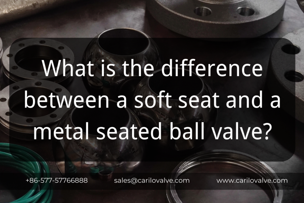
What is the difference between a soft seat and a metal seated ball valve?
It was a conversation that brought together two minds, mine from CARILO and the brilliant folks at one of oil&gas companies. In the heart of it was a cautionary tale – a reminder that even the most seasoned in the valve game can sometimes miss a beat. You see, our client, driven by their impressive vision in the oil & gas realm, once faced a hiccup. In the rush of things, they chose the wrong sealing material, not fully considering the scorching temperatures their valves would encounter. A tale of a simple oversight with significant consequences. You might be wondering, what’s the real difference between a soft seat and a metal seated ball valve? Well, my friend, it all boils down to the sealing material. Soft-seated ball valves use materials like PTFE (polytetrafluoroethylene) for their seats. This offers excellent sealing properties, making them ideal for applications where tight shut-off is necessary. On the other hand, metal seated ball valves have seats made from materials like stainless steel. This robust construction makes them better suited for high-temperature and abrasive environments. Keeping You Engaged: Now, hang on for just a bit longer. I promise, by the end of this article, you’ll be equipped with a comprehensive understanding of soft seat vs. metal seated ball valves and how to make informed choices. Soft Seat vs. Metal Seated Ball Valves: Delving Deeper Soft Seat Advantages: When it comes to soft seats, their main advantage lies in their exceptional sealing capabilities. The use of materials like PTFE results in a leak-tight seal, which is crucial for applications where even the tiniest leak could spell trouble. Industries like chemicals, where hazardous substances are involved, often opt for soft seat ball valves to ensure safety and environmental compliance. Soft Seat Challenges: While soft seats are fantastic for preventing leaks, they do come with limitations. High temperatures and abrasive fluids can cause these materials to degrade over time, affecting their sealing performance. So, while they excel in certain situations, they might not be the best choice for every application. Metal Seated Strengths: Now, let’s talk about metal seated ball valves. These valves are the workhorses of high-temperature and abrasive environments. Their seats are often made from stainless steel or other robust materials that can withstand extreme conditions. This makes them perfect for industries like oil & gas, where the fluids can be aggressive and the temperatures can soar. Metal Seated Considerations: However, keep in mind that metal seated ball valves might not provide the same level of sealing as their soft-seated counterparts. While they are reliable in harsh conditions, they might not offer the same leak-tightness that some applications demand. The Ideal Choice: So, which valve is the right one for your specific application? That’s where your expertise and partnership with CARILO come into play. By understanding the unique requirements of your industry and considering factors like fluid type, temperature, pressure, and more, you can confidently choose between soft seat and metal seated ball valves. Exploring Further Questions Can I Use Soft Seated Valves in High-Temperature Environments? Absolutely! However, for sustained high temperatures, metal seated valves might be a more suitable choice due to their enhanced durability. What About Abrasive Fluids? Metal seated valves are designed to handle abrasive fluids better, thanks to their robust construction. Leakage Concerns: Both valve types have their advantages. Soft seated valves excel in achieving zero leakage, while metal seated valves thrive in challenging conditions. Maintenance and Longevity: Soft seated valves might require more frequent replacement due to wear and tear, whereas metal seated valves are built to last longer. Balancing Cost and Performance: While soft seated valves might be more budget-friendly initially, consider the long-term costs of replacements and maintenance. Metal seated valves might prove to be more cost-effective in demanding applications. In Conclusion There you have it, my friend. The difference between soft seat and metal seated ball valves boils down to the sealing material used and the conditions they excel in. At CARILO, we understand the unique needs of the valve industry and offer a wide range of solutions to cater to various applications. With our integration of industry and trade, a professional technical team, and a dedication to quality, we’re your reliable partner in the valve world. Ready to Learn More? Welcome to consult us for in-depth insights and further information on industrial valves. And remember, the next time you’re faced with the choice between soft seat and metal seated ball valves, you’ll be equipped with the knowledge to make the right decision. Ready to Elevate Your Valve Game? Connect with CARILO today. As a leader in the valve industry, we’re here to provide you with tailored solutions, expert guidance, and a partnership that goes beyond valves – because your success is our success. Disclaimer This article is written by our engineer department and is intended to provide general information. For specific valve selection and application advice, consult with a professional in the field.
Training of department heads
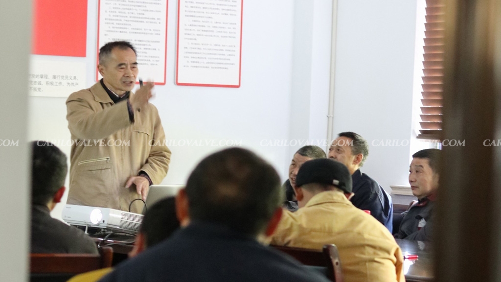
In order to expand our knowledge in valve technology and operate our plant in an efficient way. CARILO offers training in valve technology to further qualify our team.
