
Common Industrial Ball Valve Failures and How to Prevent Them | leakage issues, seat wear, improper operation
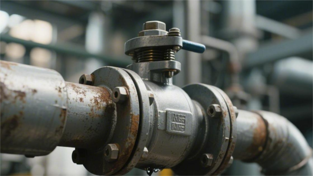
Internal leakage in ball valves and seat wear are often caused by improper operation. To prevent this, the valve must always be rotated the full 90 degrees to the fully open or fully closed position. It must never be left partially open for throttling, as high-velocity flow can erode and damage the valve body. For routine maintenance, it is recommended to perform a pressure-retained leak test and inject grease every 3 to 6 months to reduce operating torque. In addition, if the process medium exceeds 200°C or contains hard particles, the standard PTFE soft seat must be upgraded to a metal hard seat to prevent failure at the source. Leakage Issues According to testing under API 624, more than 75% of fugitive emissions in industrial piping systems originate from the stem packing area of ball valves. In Class 1500 high-pressure systems, micron-level scratches on the sealing surface can push the leak rate above 100 ppm within 48 hours. Under 200°C service conditions, PTFE exhibits a cold flow rate of 0.05 mm per hour. Internal leakage from valves can result in the loss of thousands of gallons of high-purity process media every quarter. Stem Packing Chevron V-type PTFE packing had been installed on a Class 300 pipeline for three months when the process temperature suddenly exceeded the material’s 204°C melting point. In this temperature range, the molecular structure of PTFE begins to change, causing the material volume to expand by 15% almost immediately. The stem and packing became too tightly compressed, and the coefficient of friction jumped from 0.04 to 0.12. The pneumatic actuator could no longer turn the valve, so the output torque was forced up by 60 N·m. An operator then increased the air supply pressure to 80 psi to force the valve open. That brute mechanical force tore a 3 mm split in the bottom packing ring in less than half a second, allowing high-pressure fluid to escape through the gap. At 600 psi, styrene monomer was carrying away 0.1 g of broken PTFE debris per hour. When checked with an API 624 test instrument, VOC emissions exceeded the legal 100 ppm limit in less than two days. Temperatures inside hydrocracking units in refineries run even higher, approaching 450°C. Engineers replaced the packing with 99.8% pure flexible graphite rings. Five braided graphite packing rings, manufactured to API 622, were tightly compressed into a 3.5-inch-deep stuffing box. Graphite does handle heat well, but in oxygen-rich environments it oxidizes easily. Once even a small amount of oxygen enters the line, carbon atoms begin to be consumed above 400°C. The carbon turns into carbon dioxide gas and dissipates into the air. A square graphite ring that originally measured 1/4 inch in cross-section lost 22% of its thickness after 6,000 hours of service. A stack of Belleville springs on the gland flange kept expanding to compensate for the physical gap left behind. But even with a constant 1,500 lb spring load, oxidation removed too much volume. Tensile stress in the studs dropped to less than 40% of the rated value. Use a torque wrench to set the nut preload to 45 ft-lbs. Tighten in a diagonal sequence, advancing only 1/6 of a turn per pass. Control gland compression depth to 10% to 15% of the total packing depth. Check stem runout with a micrometer and keep it within 0.05 mm. Let the assembly sit for 24 hours, then retighten once to restore lost stress. Live-loading systems offer virtually no tolerance for error. If the gland follower tilts by more than 0.5 degrees, the compressive load on one side of the packing spikes by 300%. If the metal stem surface roughness exceeds Ra 0.8 µm, the microscopic peaks act like a file. Every 90-degree valve operation scrapes a 0.01 mm layer of powder off the inner wall of the graphite rings. That debris mixes with the process medium and hardens at the bottom of the packing set, reaching a hardness close to HRC 30. The stem then jams, and two grooves 0.15 mm deep are cut into the metal surface. Replacing packing is an extremely cleanliness-sensitive job. Operators use a flexible-steel extraction tool to remove the old packing. If even a bean-sized hard particle is left behind, the newly installed five-ring V-packing set is effectively ruined. Cut the packing ends at a 45-degree skive cut. Stagger the joints of adjacent packing rings by 120 degrees. Replace the bottom anti-extrusion ring with a carbon-fiber ring. Keep the clearance between the stem and the stuffing box wall below 0.2 mm. The compressive load on the packing is highly uneven from top to bottom. The top ring takes nearly 70% of the mechanical force transmitted by the gland. The bottom two rings receive less than 10% combined. Leakage control depends almost entirely on the high-contact-pressure zone at the top. The lower packing rings mainly wipe the medium and support the stem. If too many rings are installed—more than eight, for example—the bottom three rings carry almost no load at all. Whether the valve is leaking is determined by VOC instrument readings, not by appearance alone. With a TVA2020 flame ionization detector, the probe is held 1 cm from the stem for 5 seconds. A minor temperature difference can send the reading from 5 ppm to 500 ppm. On LNG lines operating at -162°C, PTFE lip seals shrink by 2%. The adjacent metal stem contracts by only 0.5%. That mismatch in thermal expansion physically pulls apart what was once a tight sealing contact. For cryogenic service, Kel-F (PCTFE) combined with an extended stem is required. A 24-inch extension keeps the stuffing box far away from the cryogenic zone. The -162°C methane traveling through the line transfers cold through the stainless steel, but by the time it reaches the stuffing box, ambient air has moderated the temperature to above -10°C. This allows the elastomer to maintain a Shore A hardness of 75 instead of turning brittle like glass. API 622 testing places the packing assembly through thermal
How to Choose an Industrial Ball Valve for High-Pressure Applications | pressure rating, valve material, sealing performance
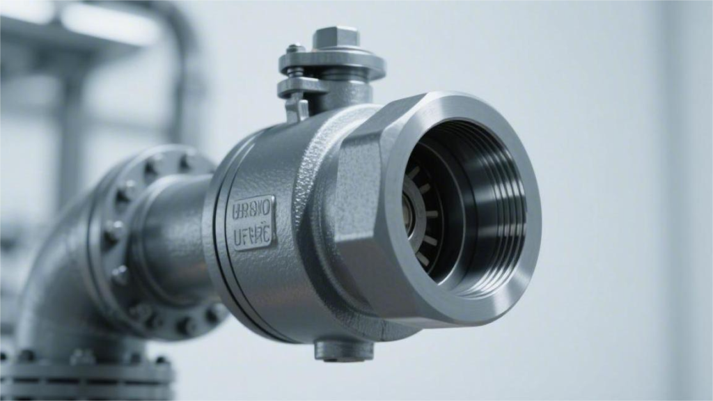
When selecting a high-pressure ball valve, prioritize Class 1500 to Class 2500 pressure ratings. The body material should be forged F316L steel to withstand extreme mechanical stress, and the sealing system must use high-pressure-resistant PEEK or a metal hard seal with a tungsten carbide-coated surface to ensure zero leakage. Before installation, a hydrostatic pressure test at 1.5 times the rated pressure must be carried out without exception. pressure rating Under ASME B16.34, pipeline pressure classes range from Class 150 to Class 4500. For a Class 1500 ball valve made of A105 carbon steel, the allowable working pressure at 38°C is 3705 psi. When the fluid temperature rises to 426°C, the maximum allowable working pressure drops to 2085 psi. In engineering design, the matching basis is typically the maximum operating pressure plus a 10% design margin. ASME Class & API A pipeline drawing shows a working pressure of 5000 psi, and the buyer uses that number to purchase an ASME Class 2500 ball valve. When it arrives at the drilling site in Texas, the flanges do not even line up. The reason is simple: the engineer specified an API 6A rated pressure on the drawing, while the ASME B16.34 pressure classes used in midstream and downstream refineries are based on a completely different system. API 6A is specifically written for upstream wellhead equipment and Christmas trees. If the nameplate reads API 5000, it means the valve can handle a cold working pressure (CWP) of 5000 psi within the standard temperature range of -29°C to 121°C. ASME, by contrast, uses a pressure-temperature derating curve. An ASTM A105 Class 2500 ball valve can take 6170 psi at 38°C, but once the pipeline temperature reaches 426°C, the allowable pressure falls to 3470 psi. What gives field crews headaches is flange incompatibility. Try mating an API 10000 flange to an ASME Class 2500 line, and the bolt circle diameter (BCD) will be off by nearly half an inch. An API 6BX 10000 psi flange has an outside diameter of 10.75 inches and is drilled with eight 1.125-inch bolt holes. The matching ASME Class 2500 flange has a 10.5-inch outside diameter and uses 1-inch bolts. You cannot force larger bolts into smaller holes, and the ring-type joint (RTJ) groove dimensions do not match either. API 10000 requires a BX 153 stainless steel sealing ring, while a Class 2500 flange is machined for an R-46 octagonal ring groove. If you force the two systems together and then expose them to 70 MPa downhole fluid pressure, the metal gasket at the joint face will be blown out of the flange gap almost instantly. Pipeline Pressure API 6A Nominal Standard (Ambient Limit) Closest ASME B16.34 Class Flange Metal Gasket Type 2000 psi API 2000 Class 900 R / RX 3000 psi API 3000 Class 1500 R / RX 5000 psi API 5000 Close to Class 2500 R / RX 10000 psi API 10000 No ASME equivalent (beyond Class 2500) BX high-pressure type only 15000 psi API 15000 Custom ultra-high-pressure range BX high-pressure type only When oil companies procure high-pressure ball valves for the North Sea, the contract will explicitly require an API 6A Product Specification Level (PSL). For ordinary water service, PSL 1 is usually sufficient. For high-pressure gas wells containing hydrogen sulfide, PSL 3 or PSL 4 is mandatory. Once the PSL level goes up, inspection standards become far more demanding. For a PSL 3 ball valve body cast from ASTM A182 F51 duplex steel, a sample must be cut from every heat and sent to the lab for a Charpy V-notch impact test. The test temperature is fixed at -46°C, and after three specimens are broken, the average absorbed impact energy must not be less than 20 joules. Miss that requirement by even one joule, and the entire batch of 50 forgings is rejected and sent back for remelting. The pressure test safety margins under the two systems are also very different. Under API 598, the shell hydrostatic test for an ASME Class 1500 ball valve is performed at 1.5 times the rated pressure, which means 5575 psi. API 6A is much more aggressive for wellhead equipment. A high-pressure ball valve marked API 10000 must be hydrotested to 15000 psi before it leaves the factory. The pressure-hold time is extended to 15 minutes, and the inspector circles the 2-inch-thick metal body with a flashlight. If the gauge drops by even 50 psi, or if a single droplet seeps from a body weld, the valve cannot be packed for shipment. Low-pressure gas test: under API 6D within the ASME system, the low-pressure gas tightness test uses only 80 psi of compressed air. Full high-pressure load: under API 6A, a PSL 3G gas sealing test requires pure nitrogen at the full rated pressure of 10000 psi. Leak detection: the entire ball valve is submerged in a rust-inhibiting water tank while high-pressure nitrogen is trapped inside the cavity. Continuous bubbling at the water surface means the tungsten carbide hard seal has failed. The two standards also draw very different red lines for material chemistry. ASTM A105 forging used for a Class 1500 carbon steel ball valve is allowed by ASME to contain up to 0.35% carbon. For an API 5000 wellhead valve made of carbon steel, API 6A limits the carbon content to below 0.23% in order to preserve toughness in subzero service. When the mill test report (MTR) arrives, inspectors focus on carbon, sulfur, and phosphorus. If sulfur exceeds 0.025%, the metal grain boundaries can develop cracks after just three months in 5000 psi sour gas service. Even the wall-thickness formulas differ sharply. ASME B16.34 allows the allowable stress to approach about 60% of the material yield strength. API 6A requires a much larger safety margin. When calculating the wall thickness for equipment rated at extreme pressures such as 15000 psi, the maximum allowable membrane stress is strictly limited to 50% of yield strength. Using that method, a ball valve designed under API for a 4-inch bore line
Flanged Ball Valve vs Threaded Ball Valve: Which One Is Better for Your Project? | installation method, sealing performance, application range
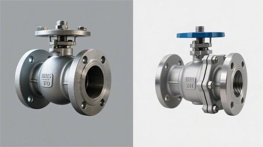
Threaded ball valves are suitable for pipelines up to DN50. Installation is straightforward: wrap the threads with PTFE tape and tighten. Their pressure rating is about 68 bar. Flanged ball valves are designed for high-pressure systems above DN50. They require a gasket and diagonal cross-tightening of the bolts. With pressure resistance up to 420 bar, they offer better sealing performance and easier removal. installation method NPT threaded ball valves manufactured to ASME B1.20.1 are suitable for pipe sizes up to DN50 (2 inches). Installation relies on PTFE thread seal tape, with pipe wrench torque typically kept between 50 and 100 N·m, and a standard installation time of 3 to 5 minutes. Flanged ball valves manufactured to ASME B16.5 are intended for pipelines above DN50 and require matching flange gaskets and high-strength bolts for assembly. A single 8-inch Class 150 flanged valve requires diagonal tightening of eight 5/8-inch bolts. The torque wrench is typically set to 120 N·m, and installation takes about 25 minutes. The flange design supports non-destructive radial removal. Replacing a threaded valve, by contrast, often requires physically cutting both ends of the rigid pipeline. Space Envelope Requirements A 1-inch NPT threaded ball valve is compact, with dimensions close to the pipe wall profile. Its overall length is only 85 mm, and its widest point is just 60 mm. That size allows it to fit inside compact skid-mounted equipment where pipe spacing is only 100 mm. Replace it with a Class 150 flanged ball valve of the same size and the two large flanges immediately increase the envelope. The overall length grows to 127 mm, and the outer diameter expands to 108 mm. At a chemical plant in Texas, pipe routing crews had to use 3D modeling to check for interference. With threaded valves, the center distance between two straight pipes could be reduced to 100 mm. In a flanged system, that no longer works. The edges of adjacent flanges can easily clash, so the minimum center distance for the same pipe size must be kept above 160 mm. Many designers forget to account for the operating handle. A standard straight handle requires a full 90-degree swing. The steel handle on a 2-inch flanged ball valve is as long as 150 mm. You need a half-circle clearance zone with a 150 mm radius directly above the valve body, or the handle will hit nearby equipment during operation. If space is tight, a butterfly-style T-handle is the better option. Because the shorter handle is split evenly to both sides, the swept area is reduced by 50% immediately. After fitting a 1-inch NPT threaded valve with a T-handle, the total operating width drops to just 55 mm. Flanged valves are bulkier, and you also need to leave enough room for the tools used during installation and maintenance: The nose of a pneumatic drilling tool requires at least an 85 mm operating radius The reaction foot of a hydraulic torque wrench needs a 45 mm support zone A bolt tensioner requires 150 mm of vertical headroom above it When using a manual wrench, the swing angle must never be less than 30 degrees With cryogenic pipelines, the insulation makes the valve envelope even larger. At the LNG terminal in Houston, the -196°C pipeline was fully sprayed with polyurethane foam. The flanged ball valve was enclosed in a rigid insulation box 100 mm thick. Because of the projecting flanges, the total volume of that insulation box was fully three times larger than that of an equivalent threaded valve. If you mount a pneumatic actuator on top of the valve, the required space increases dramatically. A rack-and-pinion pneumatic cylinder sits on the valve stem. On a 4-inch Class 300 flanged ball valve fitted with a double-acting actuator, the total height jumps by 320 mm. The stainless steel fittings for the side air line also protrude another 40 mm outward. Threaded ball valves do not require heavy tools at all. Workers can handle the entire installation using only two standard 18-inch pipe wrenches. One grips each side of the valve body at the hexagonal flats. During the job, the worker’s full operating range stays within a cylindrical working space about 400 mm in diameter. Flanged assembly demands very strict pipe alignment. ASME B31.3 limits the flange face parallelism deviation to no more than 1.5 mm per meter. Replacing a spiral wound gasket also requires mechanically spreading the two ends apart, which means extra clearance must be reserved: A spiral wound gasket with inner and outer rings is 4.5 mm thick A mechanical spreader needs 6 to 8 mm of separation to generate force To pull a bolt out completely, the gap must exceed the bolt length by 13 mm An additional 300 mm of space below is needed to hang a safety net for dropped nuts Most flanges in high-pressure systems use RTJ ring joints. The octagonal soft-iron ring gasket is tightly seated inside a trapezoidal groove. To remove a 10-inch Class 1500 flanged ball valve, the connected carbon steel pipes must be forced outward by 12 mm. This pushing force is extremely high, so the support blocks beneath the pipe rack must be lubricated to reduce friction. On North Sea offshore drilling platforms, the piping network is packed almost like a spiderweb. After running the layout through Navisworks, engineers imposed a hard rule: all Class 600 flanged valves had to be staggered. The centerlines of adjacent valves had to be at least 150 mm apart, or workers simply could not get their hands in to remove the bolts. As the valve gets larger, the support structure underneath must also become stronger. MSS SP-58 clearly requires a load-bearing support base to be welded within 500 mm of each end of a heavy flanged ball valve. The support structure itself also takes up space: The steel canister around a spring hanger has a diameter of 120 mm The welded steel plate under a saddle support can be as wide as 200 mm Once a U-bolt
How to Maintain a Flanged Ball Valve in Crude Oil Service | routine inspection, seal protection, operating practice

Flanged ball valves in crude oil pipelines must be kept either fully open or fully closed. Throttling at a 45-degree half-open position is strictly prohibited, as it allows impurities to scour and damage internal components. Routine inspections should be carried out every 3 to 6 months. Cleaning fluid and grease should be injected through the grease fitting to dissolve wax buildup and protect the PTFE sealing rings. A smooth 90-degree operating motion can significantly extend service life. Routine Inspection Flanged ball valves used in crude oil pipelines operate year-round under Class 1500 pressure conditions (25.8 MPa) and are exposed to hydrogen sulfide corrosion above 500 ppm. Routine inspections are performed in accordance with API 598, with a 30-day inspection interval. Technicians use an ultrasonic thickness gauge to measure valve body wall thickness, with accuracy controlled to within 0.1 mm. A193 B7 flange bolts must be calibrated with a hydraulic torque wrench, and preload must be maintained at 50% of yield strength. Inspection items include fugitive VOC leakage checks at the stuffing box, with a limit of 100 ppm, as well as stem operating torque tests to quantify the risk of mechanical sticking caused by asphaltene deposits. Flange Connection Seventy percent of external leaks in crude oil pipelines occur at the metal sealing faces on both ends of the valve. Take a vernier caliper and stand beside a Class 1500 pipeline. Look straight along the side. Between the two raised-face (RF) flanges sits a 316L stainless steel spiral wound gasket with an initial thickness of 4.5 mm. Crude oil rushes through the pipe at 3 meters per second, and vibration at the metal faces can reach 50 Hz. Under normal compression, the gasket thickness should reduce to between 3.2 mm and 3.3 mm. Use a 0.1 mm feeler gauge and check the four symmetrical points around the outer circumference of the flange ring. If the gap difference between any two adjacent measurement points exceeds 0.2 mm, the sealing faces have already shifted out of alignment. Fluid at 25 MPa inside the pipe will be forced outward through that misaligned gap. On ultra-high-pressure wellhead lines rated Class 2500, the raised-face design is replaced by a ring-type joint (RTJ). A soft iron octagonal ring gasket is seated inside the metal groove. Shine an explosion-proof flashlight along the groove wall. Surface roughness must remain within 63 microinches Ra. A radial scratch deeper than 0.25 mm is enough to let high-pressure crude oil break through the seal and spray out. These metal components are held together by ASTM A193 B7 high-strength studs and A194 2H heavy hex nuts. Rainwater in the Permian Basin of Texas carries a high salt content, and ambient humidity stays above 80% year-round. Exposed carbon steel studs can develop rust patches within a month. Inspection records must confirm that the metal surface has been coated with blue Xylan fluoropolymer anti-corrosion coating, typically maintained at a thickness of 20 to 30 microns. Thread rust greatly increases the friction coefficient caused by galling. The hydraulic torque wrench may be set to a pump pressure of 10,000 psi, delivering an apparent torque of 1500 N·m. On paper, the number looks fine, but the actual stud elongation may not even reach 30% of yield strength. In that case, the gasket never receives enough compressive seating stress. Field engineers in Houston trust physical data from ultrasonic bolt measurement tools more than torque values alone. Place the magnetic probe on the end face of a 2-inch stud and send a high-frequency sound wave through it. The wave travels down the 500 mm bolt, reflects from the bottom, and returns. The display directly shows that the stud has elongated by 0.85 mm. That elongation corresponds exactly to 50% of the material’s yield strength. Step back and look at the overall external assembly of the fasteners. At least two full threads must be visible outside each nut, with an exposed length of about 5 to 8 mm. Run your hand along the hex edges of the nut. There should be no rounded-off damage from rough pipe wrench use. If one stud shows a difference of more than 15 mm between the exposed lengths on both ends, the load on that assembly is severely unbalanced and the component must be replaced before the next inspection. Recording flange tightening parameters for different pressure classes is part of routine work. Every inspector carries a material-specific reference chart for verifying the hardware installed on site. Pipeline Design Pressure Class Gasket Type Required Load-Bearing Bolt Material Maximum Allowable Misalignment Gap Class 600 Spiral Wound Gasket with Inner and Outer Ring (CGI) A193 B7m (H2S Resistant) 0.25 mm Class 1500 Octagonal Metal Ring Gasket (RTJ) A320 L7 (Low-Temperature Service) 0.15 mm Class 2500 Oval Metal Ring Gasket (RTJ) A193 B16 (High-Temperature Service) 0.10 mm Crude oil flowing at high velocity through the pipeline can generate static electricity. An insulating non-metallic graphite material sits between the two metal flanges. Use a multimeter to measure the resistance of the copper bonding jumper. The reading must never exceed 10 ohms. Once resistance rises above the limit, even a tiny static spark can ignite a surrounding methane-air mixture at a concentration of 4%. In winter, ambient temperatures in the North Sea oilfields can drop to -20°C, while crude oil inside the pipe remains at 80°C. A 10-meter steel pipe can expand or contract by more than 10 mm under a 100-degree temperature difference. This physical deformation transfers enormous bending stress directly to the flange connections at both ends. Use an infrared thermometer to scan the studs and the flange ring, and record whether the temperature difference between them exceeds 30°C. Look down along the bottom of the pipeline to the ground. Even a coin-sized patch of dark brown oil on the soil must be photographed and logged immediately on the inspection tablet. Put on nitrile gloves and touch the lower edge beneath the sealing face. If black powder with a strong rotten egg smell sticks to your fingers,
Flanged Ball Valve vs Butterfly Valve in Chemical Pipelines | corrosion resistance, flow control, installation space
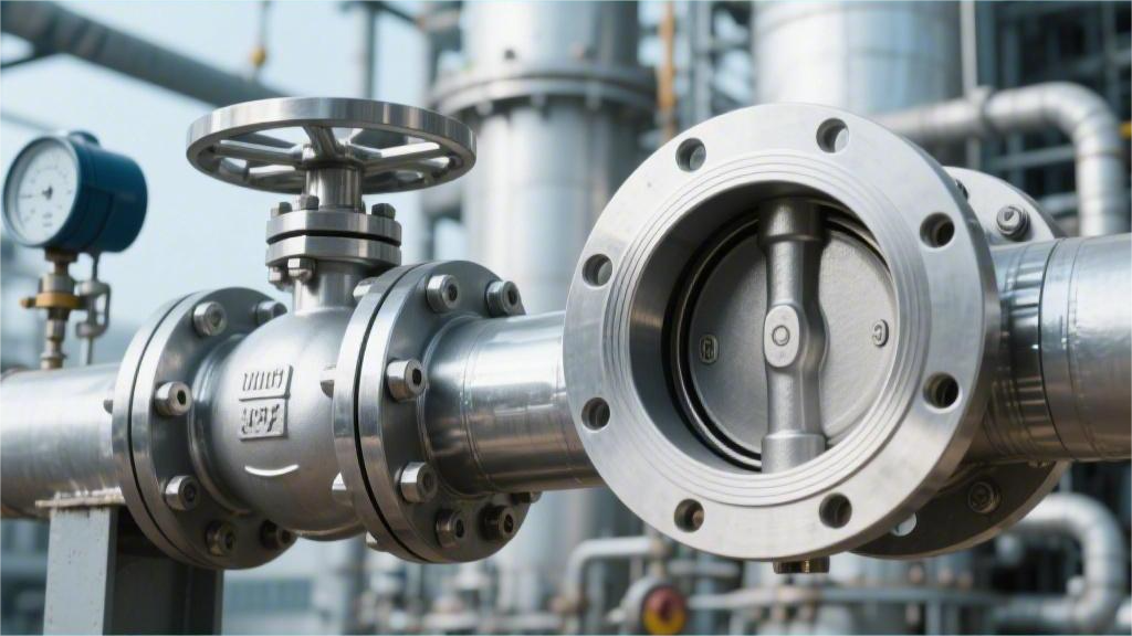
In chemical service, flanged ball valves can handle pressures up to 16 MPa, use PFA lining for strong corrosion resistance, and create virtually zero flow resistance. Butterfly valves are only about one-third the face-to-face length of ball valves, making them far more space-efficient. Both operate with a 90-degree turn, but ball valves excel at tight shutoff, while butterfly valves are better suited to large-diameter, low- to medium-pressure flow regulation. corrosion resistance When handling highly aggressive media such as 98% concentrated sulfuric acid or 30% hydrochloric acid, flanged ball valves are typically fitted with a full PFA lining of at least 3.5 mm, combined with zero-leakage sealing to API 598 standards. By contrast, the disc of a butterfly valve remains immersed in the flow path at all times. Even when made from Hastelloy C-276, the stem seal area still faces a risk of seepage at pressures above PN16. Data shows that fluorine-lined ball valves offer 25% better resistance to permeation than fluorine-lined butterfly valves. Their straight-through flow path also helps prevent localized pitting caused by media buildup. Lining & Permeation Resistance The inner cavity of a ball valve is typically cast with a 3 mm to 5 mm layer of PFA (perfluoroalkoxy). This material is introduced through high-temperature melt processing and reaches a density of about 2.15 g/cm³. Compared with cold-pressed PTFE (polytetrafluoroethylene), PFA has a tighter molecular structure, making it much harder for hydrogen ions as small as 0.1 nanometers to penetrate and reach the metal body underneath. In vacuum pipelines, for example at pressures down to -0.8 bar, many lined valves can suffer from liner collapse. To prevent the lining from separating from the metal, the inner wall of a ball valve casting is machined with multiple dovetail-style recesses. During injection molding, the PFA locks directly into these grooves, much like an anchor bolt fixed into concrete. Butterfly valve seats are usually fitted into the body without this kind of mechanical locking structure, so under negative pressure or frequent cycling, the probability of liner displacement is roughly 30% higher. The table below compares the physical anti-corrosion parameters of the two valve types: Performance Metric Fluorine-Lined Ball Valve (Standard) Fluorine-Lined Butterfly Valve (Standard) Standard lining thickness 3.5 mm – 5.0 mm 2.5 mm – 3.5 mm Processing method Melt injection Molding / encapsulation Maximum working pressure PN16 / PN25 PN10 / PN16 Vacuum resistance (150°C) Full vacuum (-0.1 MPa) Partial vacuum (-0.05 MPa) Sealing surface width 15 mm – 25 mm (large contact area) 3 mm – 8 mm (line contact) Butterfly valves have one unavoidable drawback: the disc always sits in the middle of the pipeline. Even when fully open, the medium continues to scour the disc edge. If the fluid contains 1% fine particles, those particles act like sandpaper against the lining on the disc. Tests show that at a flow velocity of 4 m/s, the lining on a butterfly valve wears 2.5 times faster than that of a ball valve. In a fully open ball valve, the bore matches the pipe I.D., so the medium flows straight through without contacting the sealing surface. The stem area is another common leak point. In a butterfly valve, the stem passes through the seat and depends on sealing at just two points. Every time the valve moves, the lining at the shaft head is compressed and deformed. When handling highly permeating media such as chlorine gas, the medium can work its way out along the stem gap. In a ball valve, the stem seal is located at the top and is continuously loaded by Belleville springs, providing a sealing contact stress above 20 MPa. Even if the lining experiences slight wear over time, the spring automatically compensates by pushing downward and keeping the gap closed. 10 kV spark testing: Fluorine-lined ball valves undergo high-voltage inspection before leaving the factory. Even a pinhole as small as 0.1 mm will be detected by electrical breakdown. Thermal expansion and contraction: The expansion coefficient of PFA is 8 to 10 times that of carbon steel. The ball inside the valve body has about 0.5 mm of movement clearance to absorb this deformation. Sealing class: Ball valves can easily achieve the gas-tight zero-leakage standard of API 598, while butterfly valves often develop seepage of 1-2 drops per minute at the sealing surface after long-term use. Highly permeating organic solvents such as dichloromethane can cause fluoroplastics to swell. Ball valve seats are usually designed with compensation features, so even if the lining swells by 5% after absorbing solvent, the valve can still operate. In butterfly valves, the disc and seat are tightly compressed against each other. Once swelling occurs, the disc can seize, and forcing it open often twists off the stem. If you compare total cost of ownership (TCO), the numbers are revealing. A DN100 fluorine-lined ball valve may cost about 50% more than a butterfly valve up front, but in severely corrosive process lines, the average maintenance interval (MTBM) for a ball valve is typically more than 36 months, whereas a butterfly valve may need seat replacement after just 12 to 18 months. In actual assembly, the flange face of a flanged ball valve is also covered directly by the lining through a turned-over flange lip. That means the medium touches nothing but fluoroplastic from inlet to outlet. This structure is especially effective when handling 98% sulfuric acid, because it eliminates the possibility of medium leaking through the flange gasket area and corroding the external bolts. Butterfly valves can use a similar structure, but because the body is thinner, the lining at the flange lip is often only about 2 mm thick, making it easier to crack under heavy bolt loading. The surface roughness of the ball in a ball valve is typically required to reach about Ra 0.2 μm. This mirror-like finish helps sweep acid off the lining surface completely during shutoff. This physical self-cleaning effect reduces how long acid remains on the sealing surface, lowering the risk of environmental stress cracking
Why Flanged Ball Valves Are Preferred in Chemical Processing Systems | leak prevention, easy maintenance, secure flange connection
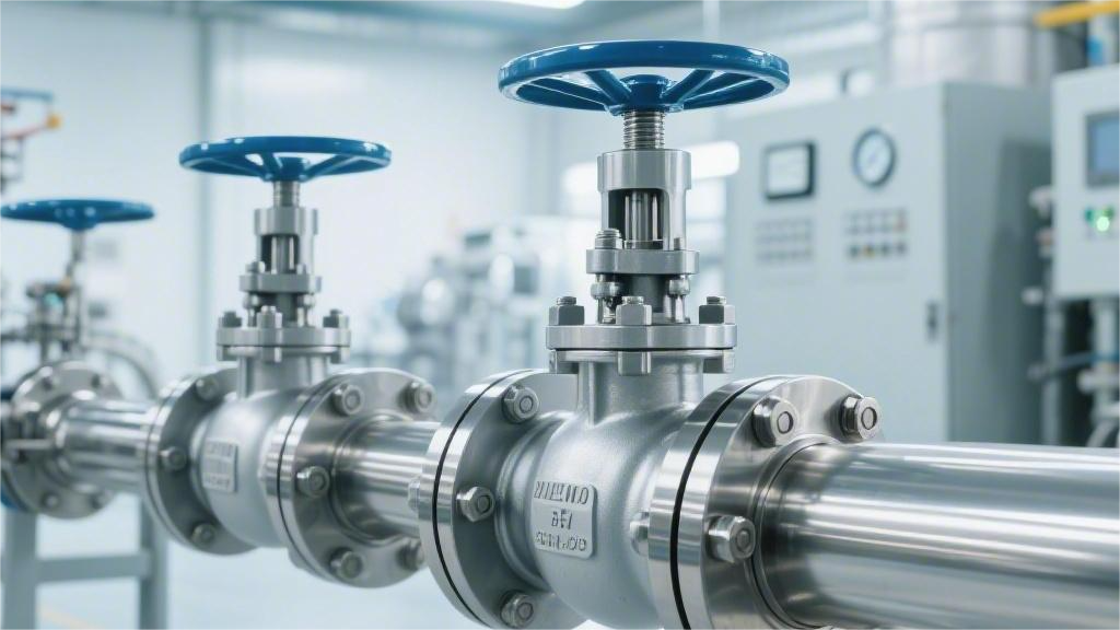
By tightening 4 to 8 flange bolts in a cross-pattern sequence and pairing them with a PTFE seal ring, the connection can withstand system pressures of up to 50 bar and keep the pipeline leak-tight. The flange connection is extremely secure, and during routine maintenance, operators can remove the entire valve simply by unbolting it, without cutting the pipe. This design can reduce maintenance downtime by about 60%, significantly improving both safety and service efficiency in hazardous chemical handling. Leak Prevention ISO 15848-1 requires VOC leakage from chemical valves to remain below 50 ppmv. Under ASME B16.5, flange face roughness is controlled within 125-250 AARH. Combined with a CG-type spiral wound gasket, the joint can withstand Class 600 pipeline pressure (10.3 MPa). The valve internals are tested in accordance with API 598 and use a disc spring-loaded V-ring PTFE packing set together with a fully enclosed seat design. When media temperature fluctuates between -46°C and 260°C, the sealing gap remains within 0.01 mm, preventing both external leakage and internal cross-port leakage. Stem Packing ISO 15848-1 classifies valve VOC leakage into three levels: A, B, and C. Class A certification requires a helium leak detector probe positioned around the stem to measure leakage no greater than 2×10^-6 mg/s·m. Conventional single-layer graphite rings cannot pass more than 100,000 open-close cycles. API 622 clearly defines the limits for physical wear and thermal weight loss of packing materials. Multi-layer Chevron PTFE packing assemblies are typically stacked in 5 to 7 layers, with each V-shaped lip usually cut at an angle between 45 and 60 degrees. When the gland follower applies downward mechanical force, the V-shaped lips expand inward and outward under compression. The inner lip seals tightly against the stem OD, while the outer lip grips the stuffing box bore. Polymeric materials experience stress relaxation during repeated thermal cycling. At -46°C, conventional PTFE can shrink in volume by approximately 1.5% to 2.5%. Live-loaded spring assemblies are used to compensate for the gaps created by dimensional change. Belleville washers are installed over the gland bolts. Belleville springs forged from Inconel 718 offer extremely high fatigue strength. Even when stuffing box pressure fluctuates up to 10.3 MPa (Class 600), the spring assembly continues to maintain a stable preload. Two opposed Belleville washers on each bolt can provide a continuous compensating torque of 50-100 N/m. Maintenance personnel do not need to routinely re-tighten the bolts by hand in the line area. Anti-extrusion rings made of PEEK or carbon-fiber-reinforced material are installed at both the top and bottom of the packing set. When high-pressure fluid migrates upward along the stem, it can generate lifting forces of several thousand newtons. Pure PTFE is prone to cold flow deformation at temperatures above 200°C. The anti-extrusion rings prevent the soft polymer from being forced into the 0.1 mm clearance between the gland and the stem. Stem surface roughness is tightly controlled within Ra 0.4 to 0.8 µm. Over-polishing prevents the packing from forming its initial lubricating film, while insufficient polishing accelerates wear of the V-rings. Cylindricity tolerance is limited to within 0.012 mm. An eccentrically rotating stem can compress one side of the packing chamber during a 90-degree turn while creating a micro-gap on the other side. The hardness differential between the stuffing box wall and the stem is selected according to reference values. Component Typical Material Specification Hardness / Friction Coefficient Applicable Temperature Range Stem 17-4 PH precipitation-hardening stainless steel HRC 38-45 -196°C to 343°C Gland Sleeve ASTM A276 Type 316 HB 217 -60°C to 400°C V-Ring Packing 15% glass-fiber-reinforced PTFE Dynamic friction coefficient < 0.1 -50°C to 230°C Spacer Ring Laminated graphite rings Fire-tested to API 607 Above 500°C A bottom-mounted blow-out proof stem shoulder is retained on the inside of the valve body. Its outside diameter is 2 to 3 mm larger than the inside diameter of the stuffing box. Even under 15 MPa line pressure, the fluid can only force the shoulder upward, where it becomes firmly trapped against the chamfer inside the body neck. A thrust washer is also installed at the shoulder. It is typically made from modified nylon containing molybdenum disulfide lubricant and is about 1.5 mm thick. The thrust washer absorbs the upward axial load on the stem and prevents galling between the metal shoulder and the metal body neck. Required operating torque is reduced by 15% to 20%. In sour service with high concentrations of hydrogen sulfide (H2S), stem material is upgraded to Monel 400 or Incoloy 825 in compliance with NACE MR0175 / ISO 15156. The nickel-alloy surface is nitrided to raise hardness to 800 HV. After 10,000 cycles of friction between the packing and the high-hardness stem, external leakage remains below 10 ppmv. The ratio between stuffing box depth and stem diameter is carefully calculated. In standard designs, total packing height is kept at about 1.5 times the stem outside diameter. If too many packing layers are used, the lower section cannot receive sufficient compressive force from the top. The bottom two V-rings remain in a relaxed state. A lantern ring is used to separate the upper and lower packing sets. The hollow cavity is connected to an external leak-off port. If the lower packing is penetrated by corrosive acid, the small amount of leaked media is diverted to a safe collection container, while the upper packing continues to block gas from escaping to atmosphere. An anti-static plunger is installed inside the stem, with a 3 mm SS 316 steel ball at the tip. An internal spring forces the ball tightly against the valve body and ball surface. Electrical current is conducted through a continuous metal path to the pipeline grounding network. Test instruments measure stem-to-body resistance at less than 10 ohms. Packing replacement is carried out using a spiral extractor with a flexible shaft. The extraction tool threads into the old PTFE ring. With approximately 30 N of pulling force, the old packing ring can be removed intact. No scratches are left on the internal wall, preventing leakage
How to Choose the Right Flanged Ball Valve for Industrial Pipelines | pressure rating, flange standard, valve material
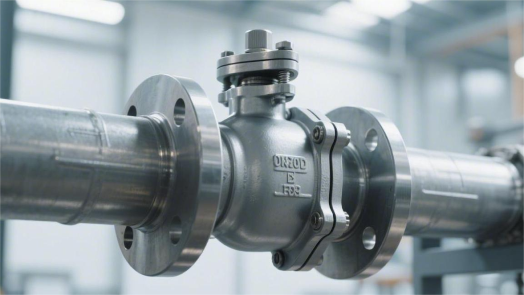
First verify the operating pressure rating (such as PN16) and the flange standard (ASME B16.5) to ensure the bolt spacing matches exactly. Then select the body material based on the medium: WCB carbon steel for standard water and gas service, and 316L stainless steel for corrosive fluids. Before installation, use calipers to measure the outside diameter. Pressure Rating In industrial piping systems, the pressure class defines the upper limit of internal static pressure that the valve body and sealing components can withstand. Under ASME B16.34, the pressure capacity of the same material can vary significantly at different temperatures. At ambient temperature (38°C), the maximum allowable working pressure of an ASTM A216 WCB Class 150 flanged ball valve is 285 psi, while a Class 300 version is rated for 740 psi. Selection calculations should include the normal working pressure plus a 10% to 15% safety margin to prevent momentary overpressure from water hammer from damaging the body or forcing out the PTFE seals. International Standard Parameters ASME B16.5 divides flange materials into 34 groups. ASTM A105 forged steel falls under Group 1.1 and is rated for 260 psi at 200°F. ASTM A182 F316L stainless steel belongs to Group 2.2, where the pressure limit at the same temperature drops to 195 psi. These pressure limits are tied directly to flange geometry. Standard tables show that flange thickness rises sharply with pressure class. A 2-inch Class 150 flange is 0.62 in (15.7 mm) thick. Upgrading to Class 300 increases the thickness of the same size flange to 0.88 in (22.4 mm). As thickness increases, the bolt-hole design is also tightly defined. A 2-inch Class 150 flange has four 0.75-inch bolt holes arranged on a 4.75-inch bolt circle and uses 5/8-inch studs for assembly. Across the Atlantic, the European system follows a different dimensional logic under EN 1092-1. For a DN50 PN16 flange, the specified outside diameter is 165 mm, the thickness is 18 mm, and the flange uses four M16 bolts. Under the same European standard, when the pressure class rises to PN40, the DN50 flange keeps the same 165 mm outside diameter. The thickness increases to 20 mm, while the number of bolts remains four and the bolt circle diameter stays at 125 mm. Standard System Nominal Size Pressure Class Flange OD Bolt Circle Diameter Number of Bolts ASME B16.5 NPS 4 Class 150 9.00 in 7.50 in 8 ASME B16.5 NPS 4 Class 300 10.00 in 7.88 in 8 EN 1092-1 DN100 PN16 220 mm 180 mm 8 EN 1092-1 DN100 PN40 235 mm 190 mm 8 In oil and gas production, compressor-station piping often follows Chapter 24 of API 6D. Once line pressure reaches Class 600, conventional raised-face flanges can develop micro-leakage, so the standard requires Ring-Type Joint (RTJ) flanges. Under this standard, a 3-inch Class 600 RTJ flange is machined with a trapezoidal groove 0.25 in (6.35 mm) deep. The bottom radius tolerance is limited to a maximum of 0.06 in. The groove must be fitted with an R-31 octagonal or oval metal ring gasket. Beyond groove design, ASME also specifies the raised-face height as a fixed value. Class 150 and Class 300 RF flanges have a raised face 0.06 in (1.6 mm) high, and this dimension is included in the total flange thickness. When the system is upgraded to Class 400 and above, the raised-face height changes. The standard increases the RF height uniformly to 0.25 in (6.4 mm), and this raised portion is not included in the nominal base thickness of the flange. In Asia, JIS B2220 is commonly seen in chemical plants. A 10K 50A flange (equivalent to 2 inches) has an outside diameter of 155 mm, which is 10 mm smaller than an EN flange at a similar pressure rating. Under the same Japanese standard, a JIS 20K 50A flange is specified at 16 mm thick, with a bolt circle diameter of 120 mm. The face is drilled with eight 19 mm bolt holes and uses M16 bolts for fastening. For large-diameter pipelines, standard dimensions are found under ASME B16.47, which includes two separate data sets: Series A and Series B. An NPS 30 Class 150 Series A flange has an outside diameter of 38.75 in and is drilled with twenty-eight 1.38-inch bolt holes. Under the other branch of the same standard, a Series B flange of the same size has a reduced outside diameter of 34.94 in. The bolt count increases to 36, while the bolt-hole diameter drops to 1.12 in to achieve a more compact piping layout. Once the main dimensions are set, surface finish affects how well the gasket seats. ASME B16.5 requires the concentric serrated finish on an RF flange sealing face to be between 125 and 250 microinches. Each inch of length must contain 45 to 55 serrations. Changing gasket materials also changes the surface finish requirement. With spiral-wound metal gaskets (SWG), flange surface roughness may be relaxed to 250 microinches. With solid PTFE sheet gaskets, a 125-microinch finish helps reduce leakage of gas media. Sealing Face Type Applicable Pressure Class Surface Roughness (Ra) Minimum Tool Mark Spacing Raised Face (RF) Class 150-300 125 – 250 µin 0.012 in Raised Face (RF) Class 400-2500 125 – 250 µin 0.012 in Ring-Type Joint (RTJ) Class 600-2500 63 µin max N/A For RTJ flanges commonly used in ultra-high-pressure piping, the machining accuracy of the groove sidewall is extremely demanding. The sealing surface roughness must not exceed 63 microinches (1.6 microns). Even fine scratches across the groove radius can destroy the zero-leak seal of the metal ring gasket. Machining accuracy is also tightly controlled by tolerance limits. EN 1092-1 clearly specifies forging tolerances. For a DN100 PN16 flange, the allowable deviation in flange OD is ±1 mm, while the tolerance on the bolt circle diameter is restricted to within ±0.5 mm. Beyond overall shape tolerance, the acceptable error in bolt-hole diameter is also tightly controlled. Under EN, the tolerance for an 18 mm hole is only +0.5 mm and -0 mm. If
What Are the Key Testing Requirements for API 6D Ball Valves | Shell Test, Seat Test, Functional Test
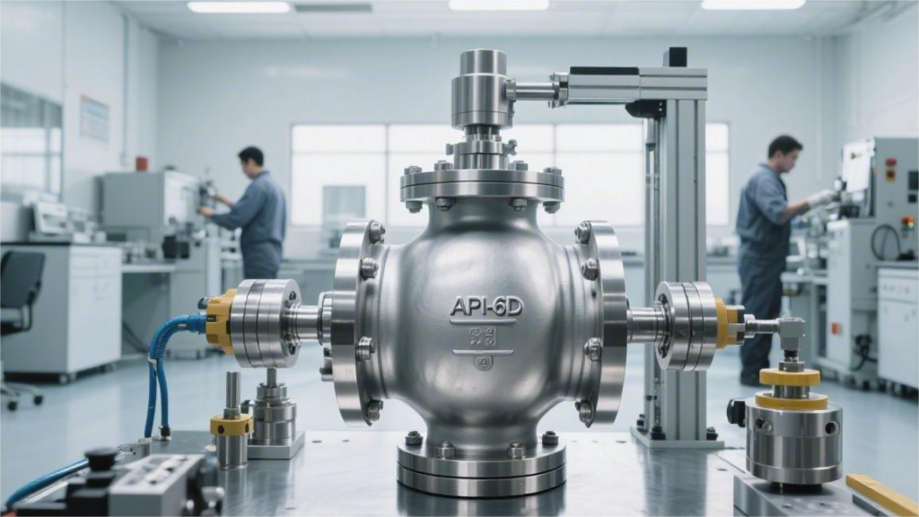
During the API 6D ball valve testing, the shell hydrostatic test requires pressurization to 1.5 times the design pressure, holding the pressure for at least 3 minutes with zero leakage; The seat test uses 1.1 times the water pressure or 0.6 MPa air pressure to detect internal leakage; The functional test requires 3 consecutive full open and close operations at the maximum differential pressure to verify that the torque is smooth and free of jamming. Shell Test The test requires the ball valve to be placed in a half-open position and injected with clean water containing a corrosion inhibitor (water temperature 5°C-50°C; the chloride ion content of the test fluid for austenitic and duplex stainless steel components must be below 50 ppm). The applied pressure must reach 1.5 times the Cold Working Pressure (CWP) rating at 38°C (100°F). The pressure holding time increases according to the Nominal Pipe Size (NPS): 2 minutes for NPS 4 and below, 5 minutes for NPS 6-10, and 30 minutes for NPS 20 and above. Pressure The physical dimensions and load-bearing capacity of API 6D ball valves are governed by the ASME B16.34 specification, covering seven classes: Class 150, 300, 400, 600, 900, 1500, and 2500. This numerical system is a dimensionless code reflecting the pressure-resistant capacity of the piping system. Within the normal temperature range of -29°C to 38°C (-20°F to 100°F), the specification assigns a clear Cold Working Pressure (CWP). The baseline water pressure set by the test equipment is entirely extracted from the CWP data tables of different material groups. ASTM A105 forgings and ASTM A216 WCB castings belong to ASME B16.34 Material Group 1.1, and the specific CWP parameters of different classes have a fixed correspondence: ASME Pressure Class Material Group 1.1 CWP (psig) Material Group 1.1 CWP (bar) Class 150 285 19.6 Class 300 740 51.0 Class 600 1480 102.1 Class 900 2220 153.1 Class 1500 3705 255.5 Class 2500 6170 425.4 The pressure boundary of metallic materials is negatively correlated with the ambient temperature; rising temperatures cause a physical degradation in the material’s yield strength. Taking a Class 600 carbon steel ball valve as an example, when the pipeline operating temperature climbs from 38°C to 200°C (392°F), the maximum allowable working pressure drops from 1480 psig to 1385 psig. The pressure drop curve of austenitic stainless steel at high temperatures is significantly different from that of carbon steel. The CWP of F316L at 38°C is 1200 psig, and it drops sharply to 860 psig at 200°C. The geometric dimensions of flanges are constrained by the pressure class assignment; flanges from NPS 1/2 to NPS 24 follow the ASME B16.5 physical dimension specification. As the class increases, the flange outer diameter, thickness, and the bolt circle diameter exhibit stepped growth. Taking a ball valve with a nominal pipe size of NPS 10 (outer diameter 273mm) as an example, the physical parameter data comparison of different classes of flanges is as follows: Pressure Class Flange Outer Diameter (mm) Minimum Flange Thickness (mm) Bolt Quantity & Size Class 150 406.4 30.2 12 x 7/8 inch Class 300 444.5 47.6 16 x 1 inch Class 600 508.0 63.5 16 x 1-1/4 inch Class 1500 584.2 108.0 12 x 1-7/8 inch Even if the steel valve body can withstand the pressure of Class 900 (2220 psig), the physical and chemical limits of the internal soft seals will force a downgrade of the rated value. The matching relationship between the maximum continuous working temperature of common high-polymer sealing materials and their applicable classes: Pure PTFE: Applicable upper limit 120°C (248°F), limited by the material’s resistance to deformation, typically restricted to Class 150 and Class 300 ranges. RPTFE (15% Glass Fiber Reinforced): Applicable upper limit 200°C (392°F), the additive improves hardness, compatible up to Class 600. NYLON: Applicable upper limit 120°C (248°F), its high-hardness property allows it to withstand the physical extrusion of Class 900 and Class 1500. PEEK (Polyetheretherketone): Applicable upper limit 260°C (500°F), possessing a tensile strength of 100 MPa, extensively covering Class 1500 to Class 2500. Fasteners bearing high pressure must meet the requirements of ASTM A193/A194 specifications. Connections for Class 600 and above specify the use of Grade B7 alloy steel bolts combined with Grade 2H nuts. When the diameter of B7 bolts is less than 2.5 inches, the tensile strength is required to reach 125,000 psi, and the minimum yield strength is 105,000 psi. The connection parameters for large-diameter pipelines (NPS 26 to NPS 60) must be executed separately according to the ASME B16.47 specification. This specification is divided into two systems: Series A and Series B. Series A flanges have a larger outer diameter and thickness, and the number and diameter of equipped bolts are higher than those of Series B. Taking an NPS 36 Class 300 ball valve as an example, if a Series A flange is used, the thickness is 104.8 mm, requiring 32 bolts with a diameter of 1-5/8 inches. If a Series B flange is selected, the thickness drops to 85.8 mm, and the bolts are adjusted to 44 pieces with a diameter of 1-1/4 inches. The calculation of the minimum metal wall thickness of the valve shell incorporates the inner diameter dimension and the stress coefficient corresponding to the class. Table 3 of ASME B16.34 details the specific inner diameter multipliers. Taking the flow path inner diameter of NPS 8 (about 203 mm) as an example, the standard specifies the absolute minimum thickness parameters for each class: Class 150: Minimum wall thickness 9.4 mm Class 300: Minimum wall thickness 11.2 mm Class 600: Minimum wall thickness 18.0 mm Class 1500: Minimum wall thickness 41.1 mm Class 2500: Minimum wall thickness 66.5 mm For products exceeding the scope of the basic ASME B16.34 charts (e.g., exceeding NPS 24 and Class 900), manufacturers independently perform wall thickness calculations based on the material strength data in ASME BPVC Section VIII, Division 1, combined with a safety factor of 1.5. The physical impact of low-temperature environments on material
How to Extend the Service Life of an API 6D Ball Valve | Proper Material, Regular Inspection, Correct Operation
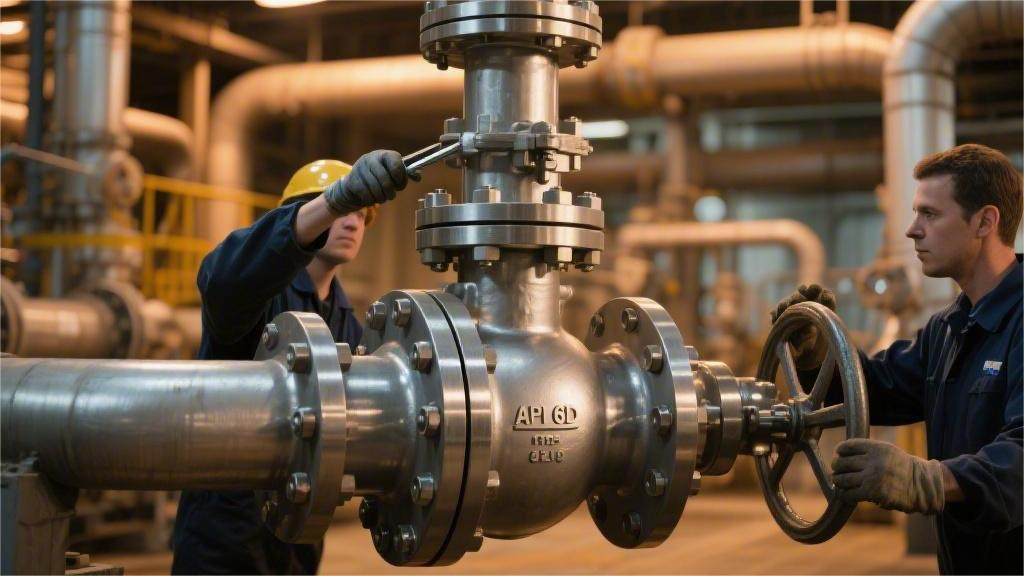
To extend the lifespan of API 6D ball valves, Inconel 625 weld overlay materials should be selected for highly corrosive conditions. Routine maintenance must strictly execute ultrasonic thickness measurements and grease injection every 6 months. They must be kept in a fully open or fully closed state; it is strictly prohibited to open them slightly for use as throttling valves, to prevent pipeline fluids from directly scouring and damaging the sealing rings at high speeds exceeding 5 m/s. Proper Material Configuring proper materials for API 6D ball valves can extend their service life from 3 years to over 20 years. The main pressure-bearing metal must match the temperature and media data: standard pipelines use A105/WCB carbon steel (withstanding 285 to 6000 psi pressure), while environments containing H₂S must comply with the NACE MR0175 standard, utilizing duplex stainless steel (PREN value > 35) to prevent cracking. Internal seals below 150°C predominantly use Devlon or PTFE, switching to PEEK for high temperatures up to 260°C; when facing media containing solid particles, it is mandatory to apply High-Velocity Oxygen Fuel (HVOF) tungsten carbide coating on the ball surface to achieve a metal-to-metal hard seal of HRC 68-72. Paired with Anti-Explosive Decompression (AED) O-rings, this directly blocks physical wear and chemical corrosion. Valve Shell The external pressure-bearing metal wall thickness calculation for API 6D ball valves follows the ASME B16.34 standard. The wall thickness formula considers the nominal fluid pressure and pipe diameter. For 24-inch natural gas pipelines in the Class 600 pressure rating, the minimum valve body wall thickness is specified as 38.1 mm. Engineering designs usually add an extra 3.2 mm corrosion allowance. To meet the set wall thickness requirements, there are two main forming processes: casting and forging. The forging process heats the metal to 1200°C and applies thousands of tons of mechanical pressure to eliminate internal porosity. The casting process pours molten steel into sand molds, forming complex flow channels upon cooling. For high-pressure pipelines of Class 1500 and above, the API 6D specification mandates the use of forgings like ASTM A105 or A694. The commonly used cast steel grade for conventional oil and gas pipelines is ASTM A216 WCB, where the Carbon Equivalent (CE) must be controlled below 0.43%. The tensile strength of A105 forged steel ranges from 70,000 to 95,000 psi, with a minimum yield strength of 36,000 psi. Both WCB and A105 grades are suitable for fluid environments from -29°C to 425°C. Manufacturing Process Common Carbon Steel Grade Yield Strength (psi) Tensile Strength (psi) Carbon Equivalent (CE) Limit Sand Casting ASTM A216 WCB 36,000 70,000 – 95,000 0.43% Open-Die/Closed-Die Forging ASTM A105 36,000 70,000 – 95,000 0.40% Sand Casting ASTM A352 LCC 40,000 70,000 – 95,000 0.45% Open-Die/Closed-Die Forging ASTM A350 LF2 36,000 70,000 – 95,000 0.42% In Canadian oil and gas fields where ambient temperatures fall below -29°C, the Charpy V-notch impact toughness of standard carbon steel drops significantly. Engineers must select low-temperature steels such as ASTM A350 LF2 or ASTM A352 LCC. According to the ASTM A370 standard, low-temperature steel tested at -46°C must have an absorbed energy greater than 27 Joules. After external metal forming, non-destructive examination (NDE) as specified by ASME BPVC Section V is required. Casting surfaces undergo Magnetic Particle Testing (MT) per ASTM E709, and internal structures are examined using Radiographic Testing (RT). Forgings undergo Penetrant Testing (PT) per ASTM E165 and are scanned with Ultrasonic Testing (UT) for transverse and longitudinal defects. The defect acceptance level is usually set at Level 2. Radiographic Testing (RT): According to ASME B16.34 Appendix I, the rating level for porosity and slag inclusions must not exceed Class 2 of ASTM E446. Ultrasonic Testing (UT): According to ASTM A388, any defect causing an echo amplitude exceeding the reference hole (3.2 mm flat-bottom hole) will be rejected. Magnetic Particle Testing (MT): No linear indications longer than 6.4 mm are permitted on the surface of steel castings. When transporting fluids with high concentrations of chloride ions on North Sea offshore drilling platforms, carbon steel will experience rapid pitting corrosion. The pressure-bearing shell material must be upgraded to duplex stainless steel (such as ASTM A890 4A or ASTM A182 F51). The F51 material consists of 50% ferrite and 50% austenite, achieving a yield strength of 65,000 psi, and its Pitting Resistance Equivalent Number (PREN) must be greater than 34. High-sulfur natural gas pipelines contain hydrogen sulfide (H₂S). According to NACE MR0175/ISO 15156 Part 3, metal components are subject to hardness and composition limits in addition to strength metrics. The maximum Rockwell hardness (HRC) limit for the material is set at 22. Post-Weld Heat Treatment (PWHT) must be executed during manufacturing to eliminate internal residual stress. The flange connection dimensions at both ends of the pressure-bearing metal comply with the ASME B16.5 specification. Class 150 to Class 600 typically use Raised Face (RF) flanges, with a surface roughness requirement between 125 and 250 microinches (Ra). High-pressure conditions of Class 900 and above utilize Ring Type Joint (RTJ) flanges machined with trapezoidal octagonal gasket grooves. Pressure Class Applicable Flange Type Flange Face Roughness (Ra) Matching Gasket Type Pressure Test Multiple Class 150 Raised Face (RF) 125 – 250 µin Spiral Wound Gasket (CG/CGI) 1.5x Nominal Pressure Class 600 Raised Face (RF) 125 – 250 µin Spiral Wound Gasket (CG/CGI) 1.5x Nominal Pressure Class 900 Ring Type Joint (RTJ) < 63 µin Octagonal/Oval Metal Ring Gasket 1.5x Nominal Pressure Class 2500 Ring Type Joint (RTJ) < 63 µin Octagonal Metal Ring Gasket 1.5x Nominal Pressure The shells of three-piece or two-piece pipeline ball valves are secured by bolts and nuts. The bolt material uses ASTM A193 B7 alloy steel, with a minimum tensile strength of 125,000 psi. Nuts use ASTM A194 2H high-carbon steel, with a hardness between HRC 24 and 35. For environments below -46°C, ASTM A320 L7 bolts are substituted to ensure low-temperature toughness. The assembled valve shell undergoes a hydrostatic shell test in accordance with the API 6D specification. The test fluid is mostly pure water containing
Which is Better: Trunnion Mounted vs Floating API 6D Ball Valve? | Torque, Pressure Performance, Valve Size
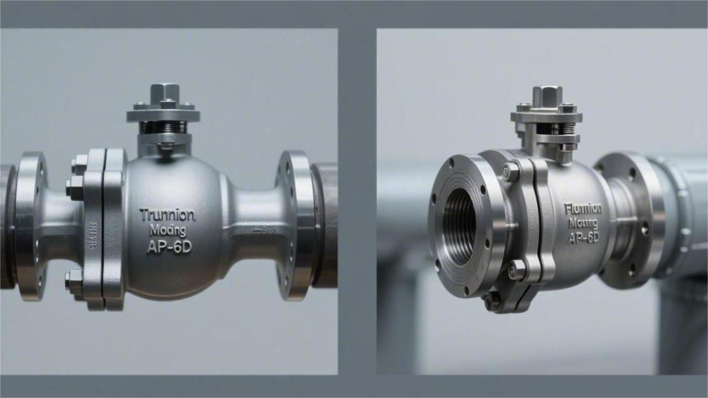
The overall performance of trunnion ball valves is generally superior. Floating ball valves rely on fluid thrust to press the ball for sealing, making them suitable for low-pressure applications of 6 inches and below Class 300. Under high pressures, their operating torque becomes exceptionally large and they are prone to wear. The ball of a trunnion valve is supported by upper and lower shafts, shifting to a design where spring-energized seats move to create the seal. This significantly reduces its operating torque, making it perfectly capable of handling extreme pressures from Class 600 to 2500, as well as large-diameter API 6D pipelines up to 60 inches. Torque Taking an ASME Class 300 (maximum allowable working pressure of approx. 740 psi), 6-inch diameter valve as an example, a floating ball valve relies entirely on the fluid pressure differential to push the ball into the polytetrafluoroethylene (PTFE) non-metallic seat. The frictional resistance generated by the high pressure differential usually causes the opening and closing torque to climb above 1500 N·m. A trunnion ball valve absorbs the vast majority of the line thrust through its upper and lower trunnion shafts and bearings, using springs to actively push the seats against the ball. Under the same physical parameters, the torque can be maintained between 400 and 600 N·m. This massive disparity in base torque means that floating ball valves in large-diameter or high-pressure scenarios must be paired with heavy-duty pneumatic actuators with large cylinder bores. The hardware procurement cost for these actuators often exceeds 40% to 60% of the budget for the bare valve itself. Floating vs. Trunnion Under the API 6D specification, the ball of a floating ball valve is supported by PTFE or PEEK seats on both sides, remaining in a suspended state. The fluid pressure differential in the pipeline pushes the 316 stainless steel ball downstream, compressing the sealing ring on a single side. When the pipe diameter remains in the 2-inch to 4-inch range, the high-molecular polymer of the seat has sufficient yield strength to withstand this thrust. When the pipe size expands to 8 inches or 12 inches, the geometric growth of the cross-sectional area causes the axial fluid thrust to surge to tens of thousands of pounds. The trunnion structure introduces a blowout-proof stem at the top of the ball and adds a load-bearing trunnion plate at the bottom, anchoring the ball at the geometric center of the valve body. The trunnion surface is covered with 316L bearings featuring a PTFE composite backing, which absorbs up to 90% of the pipeline media thrust. The downstream seat no longer bears the compression load from the ball, drastically reducing the physical wear rate. Support Components: Floating valves solely rely on non-metallic seats on both sides to support the ball. Trunnion Assembly: Trunnion valves feature an independent support shaft and self-lubricating bearing at the bottom. Spring Configuration: Trunnion valves are equipped with Inconel X-750 wave springs behind the seats. Pressure Relief Mechanism: Trunnion valves come standard with a DBB (Double Block and Bleed) bleed valve port. The transfer of physical loads brings a change in the sealing mechanism. The sealing of a floating structure is a unidirectional passive compression. When the media pressure is below 50 psi, it relies merely on the slight mechanical interference from assembly to maintain initial contact. In low-pressure gas lines, insufficient interference easily leads to ISO 5208 Rate B trace leakage. Trunnion ball valves adopt a bi-directional active push mechanism, with O-rings or pure graphite rings embedded in the inner ring of the upstream and downstream seat assemblies. Internally, 12 to 24 high-strength Belleville springs are arranged to continuously apply a pre-load of over 150 lbs to the seat. Even if the pipeline is at a 0 psi zero-pressure state, the spring groups still push the left and right floating seats tightly against the stationary ball. After ASME Class 900 (approx. 2220 psi operating limit) high-pressure fluid enters the valve cavity, the Piston Effect converts the media pressure into additional auxiliary thrust. Low-Pressure State: Floating valves rely on seat interference fit; trunnion valves rely on spring pre-loading. High-Pressure State: Floating valve ball displacement compresses one side; trunnion valve media pushes seats for bi-directional contact. Pressure Relief Function: Trunnion valves have the capability to automatically release abnormal pressure build-up in the central cavity. In NACE MR0175 wet H2S environments, liquid hydrocarbons trapped inside the valve cavity expand when heated, creating high pressure that exceeds 1.5 times the system rating. The Single Piston Effect (SPE) seats of trunnion ball valves have a pressure differential relief threshold set between 25 to 100 psi. When the cavity pressure is 50 psi higher than the upstream pipeline, the expansion force overcomes the thrust of the Inconel springs, pushing the upstream seat away from the spherical surface by about 0.5 mm. The accumulated high-pressure fluid instantly flows back into the upstream pipeline, preventing plastic deformation of the ASTM A105 forged steel valve body. Valve manufacturers’ product catalogs usually set the 6-inch diameter as a physical watershed. Class 150 6-inch pipelines can be fitted with cast WCB floating valves, keeping the total weight under 85 kg and project costs in a lower bracket. When jumping to the Class 600 pressure rating, API 6D strictly mandates that sizes above 6 inches must switch to a trunnion-mounted structure. The ASME B16.34 wall thickness calculation formula requires a Class 1500 8-inch trunnion ball valve to have a flange thickness of 82.6 mm. The API 607 fire test standard imposes rigid performance indicators for the high-temperature response of both structures. When the test furnace temperature rises to the 760°C to 980°C range, nylon or PEEK primary sealing rings will completely melt within 15 minutes. Pushed by 30 psi of residual pipeline pressure, the ball of a floating valve slides backward by about 2 mm, pressing against the metallic valve body lip machined with a 5-degree angle. The trunnion valve, however, relies on backing springs to push the metallic seat skeleton—now stripped of its soft seal—toward the
