
What Makes Ball Valve Manufacturers Competitive in Global Markets | product quality, pricing strategy, delivery reliability
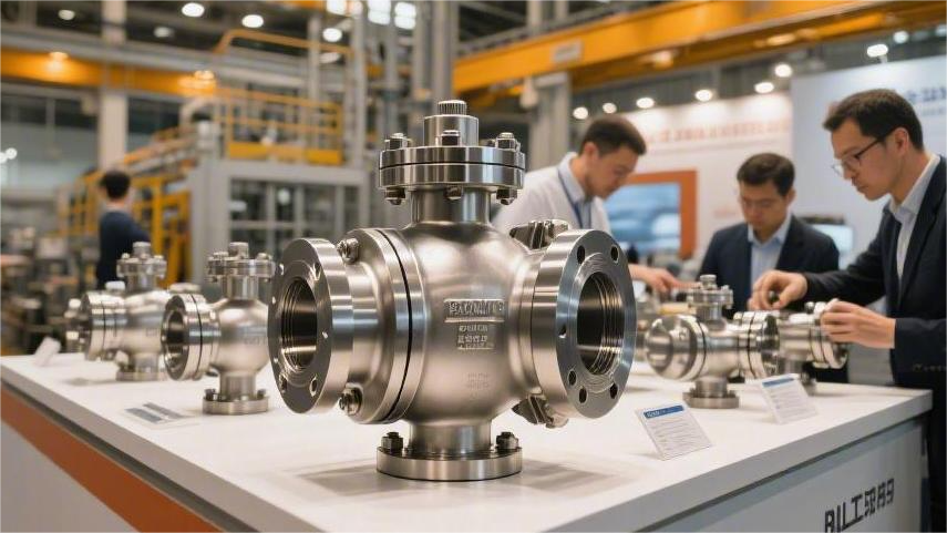
A ball valve manufacturer’s global competitiveness depends on maintaining a pass rate of at least 99%, pricing 5%–10% below comparable competitors, and keeping lead times within 30–45 days. It also requires API 6D certification, well-managed supply chain inventory with turnover within 60 days, and the use of CNC machining plus 100% air tightness testing to improve stability and customer confidence. Product Quality Corrosion Resistance & Pressure Endurance Oil pipelines operating 2,000 meters below sea level are exposed to 20 MPa of water pressure year-round, in seawater with a salinity above 3.5%. Drop an ordinary carbon steel valve into that environment, and in less than 72 hours it can corrode through under the attack of highly concentrated salt water. Many manufacturers use 2205 duplex stainless steel for the valve body. This steel contains 22% chromium, 5% nickel, and 3% molybdenum, with ferrite and austenite each accounting for half of its microstructure. Its pitting resistance equivalent number reaches 35, and its yield strength is roughly double that of standard 304 stainless steel. Even under prolonged exposure to high concentrations of chloride ions, the metal surface can resist pitting and localized attack. Different industrial pipelines carry highly corrosive fluids, forcing valve manufacturers to keep adjusting material formulas: Paper mill bleaching lines: 5% sodium hypochlorite at room temperature typically requires a titanium alloy body. Fertilizer plant synthesis zones: high-temperature ammonia solution at 190°C usually calls for 316L ultra-low-carbon stainless steel. Semiconductor cleaning workshops: 18 MΩ ultra-pure water systems require electropolished pipe walls. Offshore drilling platforms: continuous exposure to salt-laden sea air demands a 250-micron epoxy zinc-rich coating on the exterior. The metal body must withstand not only chemical attack from acids and alkalis, but also violent physical shock. In narrow pipelines, sudden opening and closing can trigger water hammer, generating impact forces three to four times higher than normal operating conditions. A ball valve rated for 10 MPa may perform routinely under standard pressure, but when a transient pressure spike hits, the internal pressure often surges to 30 MPa. Foundries send finished metal bodies into X-ray inspection rooms and use ultrasonic testing to detect tiny shrinkage cavities or gas porosity inside the casting. Even a microscopic pinhole left in an 8 mm-thick metal wall can, after three months of repeated 15 MPa pulsating pressure, grow into a major crack. Manufacturers strictly follow the wall-thickness requirements of ASME B16.34. For example, in a 2-inch Class 150 carbon steel ball valve, the thinnest section must never be less than 5.6 mm. When machining threads and flange faces, coaxial deviation is tightly controlled within 0.05 mm. Under extreme internal thrust, pressure-bearing components are pushed to their structural limits: Blowout-proof stem: designed with a larger base and smaller top so it cannot be forced out by pipeline pressure. Reinforced flange root: transition areas are formed with R5 to R10 radii to reduce fracture risk. High-strength fasteners: all bolts are upgraded to B7 alloy steel, with tensile strength above 860 MPa. Full-penetration welding: weld seams on large-diameter pipelines undergo 100% radiographic inspection. Conventional PTFE gaskets soften, deform, and get extruded from their grooves once pressure exceeds 4 MPa and the fluid temperature reaches 120°C. To solve this, workers blend 15%–25% glass fiber into the original Teflon powder and cure it at high temperature, tripling the gasket’s compressive strength. When service conditions exceed 25 MPa, even reinforced plastic gaskets fail almost instantly. At that point, manufacturers have no choice but to use metal-to-metal hard sealing, spraying tungsten carbide powder onto the ball and metal seat with supersonic flame. The hard alloy coating is applied to a thickness of 0.3 mm, with hardness measured above HRC 68. Every assembled valve is then moved to a pressure test bench. Operators seal both ends with heavy steel plates and fill the cavity with water mixed with rust inhibitor. A pneumatic pump gradually raises the pressure to 1.5 times the design pressure. A 4-inch Class 300 ball valve, for example, is held under 7.7 MPa of high-pressure water for a full 3 minutes, and not a single drop is allowed to leak. After the hydrostatic test, the water is drained and replaced with 0.6 MPa of dry compressed air. The entire valve is submerged in a clear water tank, and inspectors watch the stem and sealing areas closely for even the tiniest bubbles. For pipelines carrying toxic gases, leak detection must be done with a high-precision mass spectrometer. Even a helium leak as small as 10^-5 mbar·L/s can still be detected. Precision Manufacturing A 15 kg stainless steel forging fresh out of the furnace is covered with up to 2 mm of rough oxide scale. Before it can be installed on a chemical plant pipeline, it still has to go through more than a dozen extremely demanding machining steps. Ordinary lathes cannot handle alloys with hardness up to HB 200, so factories send them to heavy-duty CNC machining centers. Massive silicon carbide cutting tools strike the metal blank at 800 rpm, with sparks and water-soluble coolant flying everywhere. The first rough turning operation takes about 4 minutes, removing the outer 3 mm of excess material and roughly hollowing out the internal flow passage. Even after that step, the surface still has a height variation of 0.2 mm and feels rough to the touch. Whether a 15 MPa high-pressure water flow can be fully shut off depends entirely on how perfectly spherical the through-hole metal ball is. Engineers secure the semi-finished ball in a five-axis CNC machine and switch to extremely sharp polycrystalline diamond tools. During fine machining, the ball’s roundness error is strictly controlled within 0.005 mm. That 0.005 mm tolerance is roughly one-sixteenth the diameter of a human hair. If the operator’s hand slips slightly, or if the cutting tool wears by 0.01 mm, the ball may still appear acceptable—but once installed, highly penetrating natural gas can seep through nearly invisible gaps. Freshly machined metal balls are covered with fine tool marks about 0.8 microns deep, so they must be sent to
Best Ball Valve Manufacturers for Oil and Gas Applications | API standards, pressure class, material options
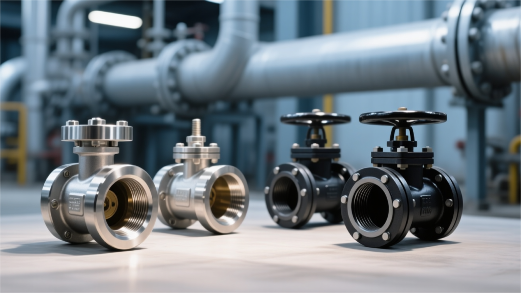
Ball valve manufacturers for oil and gas applications, such as Emerson and Flowserve, typically design to standards such as API 6D and API 608. Common pressure classes range from Class 150 to Class 2500, with upper limits approaching 1000 bar. Typical body materials include A105 carbon steel, 316L stainless steel, and duplex stainless steel. Material selection must match the medium and service conditions—for example, 2205 duplex stainless steel is often used for H₂S-containing media—while operating temperatures generally span from -50°C to 538°C. API 598 hydrostatic and sealing tests are then used to verify safety and reliability. API Standards API 6D API 6D requires a full-bore design, meaning the internal bore of the ball valve must match the pipeline bore. For a 48-inch Class 600 ball valve, for example, the seat bore is strictly specified at 1194 mm. A misalignment of even 2 mm can cause a pig, driven by dozens of tons of force, to slam into the seat and instantly shatter the PTFE sealing ring. In high-sulfur natural gas service, H₂S can easily penetrate ordinary carbon steel. When combined with moisture, hydrogen atoms accumulate within the metal and cause hydrogen-induced cracking. A350 LF2 forgings used in API 6D ball valves must therefore undergo full ultrasonic inspection before leaving the factory. Hardness is tightly controlled below 22 HRC to comply with NACE MR0175. Sulfur content in the steel must be reduced below 0.01%, and phosphorus must not exceed 0.02%. At -29°C, Charpy V-notch impact testing is mandatory. Each specimen must absorb no less than 20 joules. Internal metal and polymer components are also subject to strict material requirements: The stem uses 17-4PH precipitation-hardening stainless steel with a yield strength above 700 MPa. The ball surface is coated with tungsten carbide to a thickness of 0.15 to 0.2 mm. Springs are made from Inconel X-750 nickel alloy for stress-corrosion resistance. Seals use AED-resistant fluororubber to prevent explosive decompression damage under high-pressure gas. Bolts are ASTM A320 L7 alloy steel for low-temperature service. A 1°C rise in external temperature can generate roughly 10 MPa of pressure inside trapped liquid. Trunnion-mounted ball valves therefore include an internal cavity pressure relief design. When cavity pressure reaches 1.33 times line pressure, the spring-loaded seat automatically lifts, releasing the trapped pressure back into the pipeline so the center-flange bolts are not torn apart by hundreds of bar of internal force. Once the valve is fully closed, operators can open the drain port underneath to discharge any remaining oil. A DBB structure makes line draining significantly safer. Offshore drilling platforms often impose even stricter requirements and typically specify DIB-1 valve configurations. Both seats can withstand the force created by the double-piston effect, so even if one side fails, the other can still hold a differential pressure of up to 250 bar. Factory functional testing is also governed by fixed requirements: Fill the valve with water and pressurize it to 1.1 times the rated pressure. For 2-inch to 4-inch valves, the hold time is 2 minutes. For large ball valves over 18 inches, the hold time extends to 5 minutes. Leakage from the drain port must be zero. DIB testing requires reverse-direction high-pressure water to test each individual seat separately. API 6D also requires the anti-blowout stem design to be internal. When 15 MPa of pressure pushes outward from the pipeline, the internal shoulder locks the stem firmly against the thrust bearing. No matter what happens outside, the stem cannot be blown out by internal pressure and injure personnel. Valves that sit idle for months often require very high breakaway torque on first operation, so actuators are typically oversized by a factor of 1.5 to 2. Take an NPS 36 Class 900 trunnion-mounted ball valve as an example. The factory test torque is specified at 80,000 N·m. Its pneumatic actuator can deliver 150,000 N·m of torque. The adjacent control cabinet contains a 500-liter high-pressure air tank, with enough stored energy to perform three consecutive operations—open, close, then open again. The flange bolts on the valve body must not only contain the internal pressure but also withstand bending moments of several hundred kilonewtons caused by thermal expansion and contraction of the pipeline. A fully welded ball valve eliminates the center flange entirely, with the body closed by two submerged arc welds. These welds are fully radiographed and evaluated to ASME BPVC Section VIII. For buried service, the exterior is coated with a 1.5 to 2.5 mm polyurethane anti-corrosion layer. Inspectors then use a 15,000-volt holiday detector to scan the coating and identify pinhole-sized defects. API 608 When installing metal ball valves in process piping, workers must purchase them to API 608. The standard covers sizes from as small as 1/4 inch up to 24 inches. Pressure classes are limited to Class 150, Class 300, and Class 600. The base ASME B16.34 standard does not provide enough protection for highly corrosive chemical service. API 608 adds a mandatory 2.5 mm corrosion allowance on top of the original wall-thickness formula. On a 2-inch Class 300 carbon steel valve, for example, the body wall thickness must never be less than 8.6 mm. At the stockyard, inspectors use handheld spectrometers to verify incoming material: WCB carbon steel must contain less than 0.30% carbon. CF8M stainless steel contains 2.0% molybdenum. Forged material must have a forging reduction ratio of 3:1. Ultrasonic testing must be able to detect internal cracks as small as 2 mm. Machinists turn a 3 mm shoulder disk at the bottom of the stem. Even if all gland bolts fail, 10 MPa of heavy oil inside the line still cannot blow out a stem designed with anti-blowout retention. With a one-meter lever, the required operating force must not exceed 360 N. On gear-operated valves, the rim force at the handwheel must remain under 80 N. If the measured value even slightly exceeds the limit, the entire gearbox is dismantled and sent back to the workshop for re-gearing. Class 300 ball valves larger than 4 inches use a heavy bottom shaft
What to Look for When Buying an Industrial Ball Valve | sealing performance, material options, low maintenance
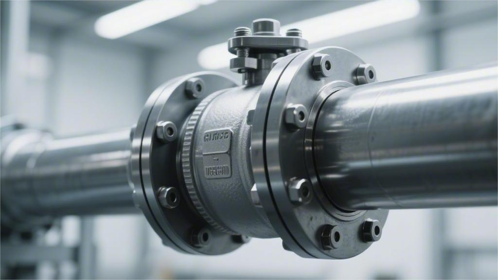
Industrial ball valve selection should target ANSI Class VI shutoff performance, with CF8M stainless steel as the preferred body material for PN64 high-pressure service. To reduce maintenance costs, specify an ISO 5211 direct-mount pad together with live-loaded self-compensating stem packing. Leaving a 15% torque margin during installation helps ensure smooth long-term operation and significantly extends sealing life. Sealing Performance Seat Materials PTFE seats typically have a hardness of Shore D 50 to 60 and a density of 2.14 g/cm³. Under service temperatures around 150°C, this material is prone to cold flow, behaving almost like soft putty. Once pressure exceeds 5 MPa, the sealing surface can thin under compression, leading to internal leakage. RPTFE, reinforced with 15% glass fiber, increases hardness to around Shore D 65. At 14 MPa, its resistance to extrusion is roughly 30% higher than that of virgin PTFE. A 25% carbon-fiber-filled grade can reach a thermal conductivity of 0.6 W/(m·K), dissipating heat at more than twice the rate of standard PTFE. TFM 1600, a modified PTFE, has a lower internal void ratio than standard grades. Its permeability is only about half that of conventional PTFE, providing stronger gas barrier performance. After 5,000 cycles at 20 MPa, seal wear remains below 0.05 mm. Even at -100°C, it still retains 5% elongation and does not fail in a brittle, glass-like manner. PEEK offers a tensile strength of 100 MPa and a melting point of 343°C. In 250°C steam service, dimensional deviation can be held within 0.02 mm. Devlon V-API reaches Shore D 82 with water absorption below 0.1%, solving the swelling and sticking issues common in wet gas field conditions. Nylon 6 provides compressive strength above 80 MPa. With its low coefficient of friction and good impact resistance, it is often used in crude oil pipelines carrying sand or grit. In Class 2500 high-pressure valves, the back of the seat is typically fitted with a Viton GLT O-ring to maintain sealing elasticity at -40°C. Metal-seated valves generally use seat thicknesses ranging from 5 mm to 12 mm. Their surfaces are often coated by HVOF spraying with an alloy of 88% tungsten carbide and 12% cobalt. The coating hardness exceeds HV 1100, equivalent to over HRC 70, allowing it to withstand welding slag and hard mineral debris in the pipeline. Stellite overlay thickness should be at least 1.5 mm. After coating, ball roundness deviation must remain within 0.01 mm. The sealing surface should achieve a roughness of Ra 0.1 μm, with a true mirror finish. An Inconel 718 wave spring behind the seat provides initial preload. Chromium carbide coatings can remain stable up to 815°C, resisting oxidation and spalling at high temperature. For every additional 0.01 mm of roundness error on the ball surface, closing torque rises by about 15%. Under frequent cycling, poor roundness can cause localized seat wear of up to 0.2 mm. The flat engagement tolerance between the stem and the ball should be limited to within 0.05 mm. The stem packing box should contain 5 to 8 rings of high-purity flexible graphite. Standard graphite purity is 98%, minimizing chemical pitting on the stem. Stem surface finish should reach Ra 0.4 μm; once roughness exceeds Ra 0.8 μm, graphite packing may be ground into powder within 100 operating cycles. ISO 15848-1 AH class requires a helium leakage rate below 10^-6 mg/(s·m). API 622 requires the packing to withstand 1,510 thermal cycles at 260°C. Live-loading should use three sets of 17-7PH disc springs. The spring stack must provide sustained compression above 20 MPa to offset packing wear. API 607 fire testing simulates flame exposure at around 900°C. Once the soft seat is burned away, process pressure forces the ball against the metal shoulder inside the valve body. This metal-to-metal secondary seal must limit external leakage to only a few dozen milliliters per minute per inch of valve size. Rising cavity pressure is a major risk factor in valve failure. When trapped liquid inside the cavity expands under heat and pressure exceeds 1.5 times the line pressure, an SPE single-piston seat can lift like a relief valve to discharge pressure. DPE double-piston seats provide bidirectional sealing, but in liquid service above Class 600 they require an external relief valve. When chloride concentration exceeds 50 ppm, 316 stainless steel balls can suffer pitting corrosion. Duplex 2205 has a yield strength of 450 MPa, roughly twice that of 316. This higher strength helps prevent even microscopic seat support deformation above 0.02 mm under pressure fluctuation. PCTFE is specifically used for liquid nitrogen service at -196°C. Its coefficient of thermal expansion is tightly controlled at 0.000045/°C to prevent shrinkage issues at low temperature. A 24-hour cryogenic treatment is required before machining to eliminate residual internal stress. The sealing contact width is typically controlled between 2 mm and 4 mm to balance shutoff performance and service life. Sealing contact pressure is generally set at 1.2 to 2 times the process pressure. Excessive preload can drive operating torque from 50 Nm up to 120 Nm, accelerating wear of the actuator gears. By adjusting the R-angle profile of the seat seal ring, shutoff tightness and operating smoothness can be balanced more effectively. When purchasing, the EN 10204 3.1 certificate should include full chemical composition data. Pressure test reports should clearly state the hold times for both high-pressure hydrostatic and low-pressure pneumatic testing. For a DN200 valve, the high-pressure test must hold for at least 60 seconds with no visible pressure drop to be considered acceptable. International Leakage Testing API 598 specifies that low-pressure pneumatic seat tests must be conducted between 0.4 and 0.7 MPa. For a soft-seated DN50 ball valve, the test must last at least 15 seconds with no visible bubbles. If the size increases to DN200, the required duration rises to 60 seconds. For the high-pressure hydrostatic strength test, the test pressure must be 1.1 times the rated working pressure. If water is used as the test medium, chloride content must not exceed 50 ppm to prevent pitting of stainless steel balls.
Which Industrial Ball Valve Material Is Best for Harsh Environments | stainless steel, carbon steel, chemical resistance
316 stainless steel ball valves outperform carbon steel in harsh environments. With 2%–3% molybdenum, they can withstand strong acid and alkali corrosion as well as temperatures up to 450°C. When selecting a valve, if the process fluid has a pH below 6, switch directly from carbon steel to a 316L flanged ball valve to prevent rust and leakage and to help keep the system maintenance-free for 10 years. Stainless Steel Chemical Stability When 65% nitric acid rushes through a pipeline, the inner wall of ordinary carbon steel will start bubbling violently in less than 3 seconds. With 18% chromium, 304 stainless steel keeps the corrosion rate in strong oxidizing acids below 0.02 mm per year at room temperature. Oxygen atoms in nitric acid continuously replenish the metal surface, so even if the 1–5 nm chromium oxide film is scratched by sand or debris, it can reform almost instantly. At room temperature, 304 can barely tolerate nitric acid below 10% concentration or in the very high range above 85%, limiting metal loss to about 0.1 mm per year. But around 50% concentration, once the liquid temperature rises above the critical 40°C, the surface film can dissolve and peel off completely within hours. This is where 316 stainless steel, with 2.5% molybdenum, takes over. Molybdenum atoms act like anchors in the crystal lattice, locking iron atoms in place. In 20% sulfuric acid at 60°C, the annual corrosion loss of 316 drops to just one-fifteenth of that of 304. When liquid alkali reaches 50% concentration and furnace temperatures exceed 80°C, nickel at the grain boundaries becomes essential. With 10%–14% nickel, 316 stainless steel keeps annual metal loss below 0.05 mm even in hot, concentrated caustic solutions. In plants handling hazardous chemicals, veteran supervisors usually keep a strict fluid compatibility chart close at hand: 98% sulfuric acid: flow velocity must not exceed 1.5 m/s 20% hydrochloric acid: 300-series stainless steels are prohibited 65% nitric acid: operating temperature must stay below 85°C 50% caustic soda pipelines: stress-relief annealing is mandatory Once a ball valve and pipe flange are welded together, the weld zone can enter the dangerous 425°C–815°C sensitization range within seconds. If the torch lingers for just two extra minutes, carbon atoms inside the grains migrate to the boundaries and combine with chromium, forming large amounts of chromium carbide precipitates. As chromium is depleted, the free chromium content at the grain boundaries can drop below the critical 10.5% threshold. Even mildly corrosive fluids can then creep into microscopic gaps. In less than three weeks, a once-solid valve weld can turn into a sponge-like structure full of corrosion pits, with high-pressure fluid ready to burst through at any time. Modern steelmaking uses AOD argon oxygen decarburization to strip carbon from molten steel. Standard 304 stainless steel allows up to 0.08% carbon, while 316L stainless steel cuts that to below 0.03%. With less carbon available, welding can no longer cause enough carbide precipitation to rob chromium from the weld area, so the gaps in corrosion resistance remain protected. On fabrication sheets handed to welders, a few rules are never negotiable: Standard 316: carbon content ≤ 0.08% 316L: carbon content ≤ 0.03% Avoid the 425°C–815°C sensitization range L-grade stainless steel should not be used continuously above 426°C Semiconductor etching lines often run 99.5% glacial acetic acid every day. At room temperature, it is fairly stable. But once a little water mixes in, or the liquid nears its 118°C boiling point, free acetic acid molecules begin attacking the underlying iron atoms in groups. Machining centers mechanically polish the valve bore to a surface roughness below Ra 0.4 μm, leaving it so smooth that even organic residues struggle to cling to it. Then the surface is pickled and passivated to remove microscopic free iron, raising the chromium-to-iron ratio from 1.2 to above 2.5, effectively sealing off the pathways that acetic acid molecules would otherwise exploit. Natural gas from oil and gas wells often contains toxic hydrogen sulfide. Once the partial pressure exceeds 0.05 psi, hydrogen atoms released during hydrolysis—only 0.053 nm in size—can squeeze into metal gaps. These atoms combine into hydrogen molecules, expanding several times in volume and forcing cracks open along the grain boundaries. Valves built to NACE MR0175 sour-service standards must keep hardness below 22 HRC. A slightly softer metal lattice provides more flexibility, allowing hydrogen atoms to diffuse through microscopic voids and escape instead of accumulating and rupturing the steel from within. Paper mills use wet chlorine gas to bleach pulp. Once mixed with water, it turns into hypochlorous acid. Its molecules are small and extremely oxidizing, and the normal 1–5 nm chromium oxide film offers little protection. 317L stainless steel, with 3%–4% molybdenum, can double service life in wet chlorine environments. Negatively charged chloride ions target the weak points in passive films. At just 0.181 nm, they can penetrate the nanoscale oxide layer and combine with iron atoms beneath it to form soluble ferrous chloride. In high-flow pipelines, the dissolved material is constantly washed away, and before long the bright steel surface becomes riddled with fine pinhole pits. 304 vs. 316 When purchasing ball valves for water treatment plants, suppliers usually offer 304 stainless steel first. With 18% chromium and 8% nickel, it is more than adequate for purified water. In dyeing and finishing plants in Jiangsu and Zhejiang, where valves are installed on weakly acidic waste liquid lines, this cost-effective alloy combination can last for years in environments around pH 5.5. Move that same pipeline to a coastal saltworks, and 304 quickly reaches its limit. Seawater contains about 35,000 ppm chloride ions. After two months of sea breeze exposure, the bright silver valve body will start showing reddish rust spots. On chemical plant drawings, buyers often revise the material callout directly to 316 stainless steel, precisely because it can resist the aggressive chloride attack of saltwater. When steelmakers add 2%–3% molybdenum, 304 effectively becomes 316 in terms of chemical resistance. On the spot market, pure molybdenum powder can cost nearly RMB 450,000
What Is the Difference Between Full Port and Reduced Port Industrial Ball Valves | flow capacity, pressure loss, application fit
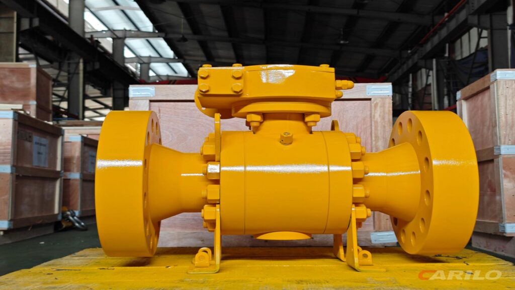
Full-port ball valves have a bore equal to the pipe I.D., delivering 100% flow capacity with extremely low pressure loss. They are ideal for applications that require pigging or the transfer of high-viscosity fluids. Reduced-port ball valves usually have a bore one size smaller than the pipe connection size—for example, a 2-inch valve with a 1.5-inch bore. Flow capacity typically drops to around 70%, with a noticeable pressure drop, making them suitable for conventional clean water or gas systems where pressure loss is not critical. Flow Capacity Full-Port Ball Valve Take a 4-inch valve as an example. Measure the diameter of its internal passage with a caliper, and it comes out to 102.26 mm—exactly the same as the inside diameter of the connected standard steel pipe. As water passes through this metal passage, the flow stream does not contract at all. It maintains the same velocity of 2.5 m/s it had before entering the valve. The friction factor between the pipe wall and the water remains at a very low 0.015. When calculating resistance, the K value of this type of valve is only 0.05, whereas a traditional shutoff valve of the same size can have a K value as high as 5.5. As the water flows through this 150 mm-long metal cavity, it behaves almost as if it were passing through an ordinary straight pipe. That tiny difference in resistance is directly tied to the plant’s power bill. A 75 kW pump running 24 hours a day, transporting clean water with a density of 1000 kg/m³, will see less than 0.5 psi of total pressure loss across a network containing 10 of these equal-bore valves. Over 365 days of continuous operation, the pump motor will consume around 650,000 kWh. Replace those valves with ordinary models whose internal passage is 20% narrower, and the pump must work against an additional 30 psi of resistance. To move the same volume of water, annual power consumption jumps to more than 720,000 kWh, wasting tens of thousands in electricity costs. Because the inside of the passage is smooth and step-free, even fine sand particles suspended in the water have no reason to impact and abrade internal surfaces. When the pipe is carrying ore slurry containing 15% quartz sand, the internal geometry becomes a decisive factor in service life. Sand particles move straight through an equal-bore passage. The probability of impacting the central metal ball surface stays below 2%. Annual wear on the stainless-steel base is only 0.05 mm. Lateral pulling force on the adjacent sealing ring is reduced by 60%. Oilfield maintenance crews keep detailed records of pigging cycles. A 50 km crude oil pipeline may require a 200 mm polyurethane pig every month. Driven forward by a 0.5 MPa pressure differential, the pig scrapes off wax deposits up to 3 mm thick from the pipe wall. When the pig passes through a full-port valve, the contact between its outer rubber skin and the valve wall remains above 99%. With no internal steps or sudden restrictions, tens of kilograms of sticky wax and sludge can pass smoothly through the center. The rubber skin is not cut by metal edges, and the pig arrives intact at the receiving station 50 km away. Highly viscous fluids are especially sensitive to passage diameter. At -10°C, heavy oil can reach a viscosity of 2000 cSt. Under these conditions, even a 1 mm reduction in internal diameter can force the downstream transfer pump to deliver an extra 1.5 kW of power. Heavy oil flows slowly through a 200 mm pipe at 0.8 m/s. Wall adhesion resistance remains at 50 Pa. Outlet flow stays stable at 150 m³/h. Severe pipe vibration caused by flow instability is avoided. In dairy plants, CIP cleaning is carried out with 85°C, 2% caustic solution. Flowing through the valve at 2.5 m/s, the solution can remove 99.9% of milk fat residue in just 5 minutes. Any unreachable dead zone is less than 0.1 cm², and measured bacterial counts remain far below the national limit of 100 CFU/g. The polymer seat seals tightly against the metal ball. In a Class 150 line, the assembly withstands a hydrostatic test pressure of 1.96 MPa. When the valve is fully open, the erosive force of the water on the plastic sealing face is reduced to a minimum. The plastic seat can reliably withstand 50,000 operating cycles. At a coastal LNG terminal, cryogenic pipelines impose extremely strict dimensional requirements on metal components. Liquefied natural gas at -162°C flows through a 24-inch line at 5000 m³/h. Ultra-low temperature causes stainless steel to contract by about 0.3%. A full-port design leaves adequate room for thermal expansion and contraction. Daily gas boil-off is kept below 0.05%. The temperature difference across the valve remains within 0.2°C. Buying an 8-inch carbon steel full-port valve may cost RMB 12,000 initially. But over three years of operation, it can save the trouble of two unplanned shutdown repairs. Each replacement requires 4 experienced technicians working for 6 hours. In a chemical plant, one day of downtime can mean losing 30 tons of plastic pellets. At RMB 8,000 per ton, that is RMB 240,000 in lost output in a single day. A few extra millimeters of full bore on a drawing can turn into real money over hundreds of days of continuous operation. Reduced-Port Ball Valve Open up a reduced-port 2-inch valve connected to a 50 mm water pipe, and the opening through the stainless-steel ball is only 38 mm. Water that originally filled the entire pipe cross-section must suddenly squeeze through a narrow throat. The flow area drops by nearly one-third, and velocity rises instantly from 1.5 m/s to 2.3 m/s. Water crowds through the 38 mm opening and then expands abruptly downstream, striking the pipe wall. Manufacturers describe this with the Cv value. A full-port 2-inch valve can reach around 410, while a reduced-port design drops to about 130. The gauge tells the truth: the flow loses roughly 1.2 psi of pressure passing through the
Best Industrial Ball Valve Options for High-Pressure Applications | sealing performance, body strength, service life
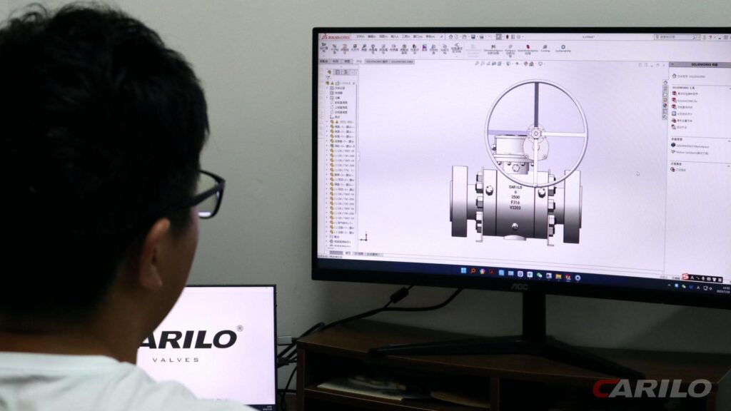
For extreme high-pressure service, a forged steel F316L trunnion-mounted ball valve is the preferred choice to withstand ultimate pressures up to 10,000 PSI. The sealing system should use a PEEK seat paired with a tungsten carbide coating to ensure zero leakage under a 400 bar differential pressure. A gear operator must be used for slow opening and closing to prevent water hammer, and 100,000-cycle pressurized actuation test data should be verified to ensure long-term service life. Sealing Performance High-Pressure Conditions In subsea pipelines 3,000 meters below the Gulf of Mexico, heavy crude loaded with large amounts of quartz sand flows continuously through the line. Internal pressure can reach a staggering 15,000 PSI, roughly equivalent to balancing the weight of a small car on the area of a fingernail. The surrounding seawater stays at 2 to 4°C year-round, while the pipe wall is repeatedly hit by crude oil at 130°C. That severe temperature differential causes the thick steel to expand and contract every day in ways the naked eye cannot see. A standard PTFE gasket would not survive even five minutes in this environment. Under hundreds of tons of pressure, it would deform like chewing gum and extrude past the edge of the steel flange. For deep-sea ball valves, the seat base is upgraded to duplex stainless steel F51, a material with an impressive tensile strength of 620 MPa. Inside that rigid base sits an extremely thin high-performance PEEK ring. Only 0.5 mm protrudes above the metal surface. Any more would be crushed instantly under pressure; any less would fail to seal against the ball. The machining center must hold the dimensional tolerance of that sealing groove within ±0.02 mm, roughly one quarter of the diameter of a human hair. Workshop temperature is kept constant at 22°C Cutting feed rate is set at 0.05 mm per revolution Measurements are taken with a coordinate measuring machine Surface finish must reach Ra 0.4 μm A hydraulic motor delivers 12,000 N·m of torque to rotate a two-ton ball, and at that scale, friction becomes intensely destructive. Sharp-edged quartz particles scour the sealing surface at 15 m/s. A pure plastic seat would already have been ground into invisible powder and flushed away by the flow. To solve this, engineers apply a tungsten carbide coating to the surface of the solid stainless steel ball using HVOF spraying. This gray protective layer is only about 0.3 mm thick, yet its hardness reaches HRC 72, enough to scratch bulletproof glass. But a hard ball and an equally hard metal seat alone are not enough to stop high-pressure media. The two components must undergo a matching lapping process that lasts 48 hours. Workers spread a gray-black lapping compound across the contact surface and use a pneumatic actuator to simulate normal opening and closing cycles, rubbing the parts together tens of thousands of times. 400-grit diamond abrasive for rough lapping 1000-grit abrasive for semi-finishing 3000-grit diamond paste for final lapping Contact ratio must exceed 95% After lapping, the two metal contact surfaces become mirror-like, with almost no dead angles. The fit is so precise that even a water droplet as small as 0.005 mm cannot pass through. Leak testing no longer relies on watching for water droplets. The factory uses high-pressure helium instead. The fully assembled ball valve is placed inside a sealed vacuum chamber, and helium is pressurized into the pipeline cavity. Helium atoms are only 0.26 nanometers in diameter and are extremely penetrating. A probe scans repeatedly along both ends of the valve body, searching for any escaping molecules. If the mass spectrometer shows a leak rate higher than one hundred-thousandth of a cubic centimeter per second (1.0E-5 cc/sec), the entire five-ton valve—worth USD 200,000—must be disassembled and rebuilt from scratch. Even when the process fluid is fully blocked inside the line, the area where the stem exits the body remains the most vulnerable escape path for high-pressure gas. The valve stem rotates dozens of times a day to regulate flow, and repeated metal friction gradually opens fatigue gaps in the packing material. The stuffing box is packed with five alternating rings of flexible graphite. The three middle rings have a density of 1.4 g/cm³ and mainly absorb radial expansion pressure. The two outer graphite rings are reinforced with ultra-fine stainless steel mesh, raising their density to 1.6 g/cm³. Workers then tighten the hex bolts to 150 N·m with a torque wrench, compressing the graphite firmly around the stem. This arrangement can hold gas securely inside the valve body under Class 2500 pressure ratings, or roughly 42 MPa. In refinery lines handling hydrogen sulfide, operating pressure often rises to 20 MPa. At just 10 ppm, H₂S gives off a strong, offensive smell; at 800 ppm, inhalation can stop breathing within minutes. That is why 4 or 6 disc springs are stacked in a specific opposing sequence on the gland bolts, providing about 3,000 pounds of continuous preload. Spring material: 50CrVA spring steel Surface treatment: zinc-plated for corrosion resistance Pre-compression: 2.5 mm Fatigue life: over 100,000 cycles As the graphite rings gradually wear down by 0.1 mm over time, the springs extend automatically and fill the newly formed micro-gaps. Another hidden danger appears once both ends of the pipeline are sealed by the valve: the residual liquid trapped in the cavity between them. Under desert sun, cavity temperature can rise from 25°C to 60°C, and the crude oil inside expands violently. Based on the liquid’s volumetric expansion coefficient, internal hydraulic pressure can rise by 75 PSI for every 1°C increase. In less than an hour, pressure can exceed the yield strength of the cast steel body. Even a 50 mm-thick carbon steel shell can split under that force. To prevent this, an Inconel X-750 spring hidden behind the seat takes over the pressure-relief function. When cavity pressure exceeds upstream line pressure by about 100 PSI, the spring compresses backward by 1 to 2 mm. That tiny movement is enough to let a few drops of crude oil escape
How to Select an Industrial Ball Valve for Corrosive Media | corrosion resistance, seat material, long-term reliability
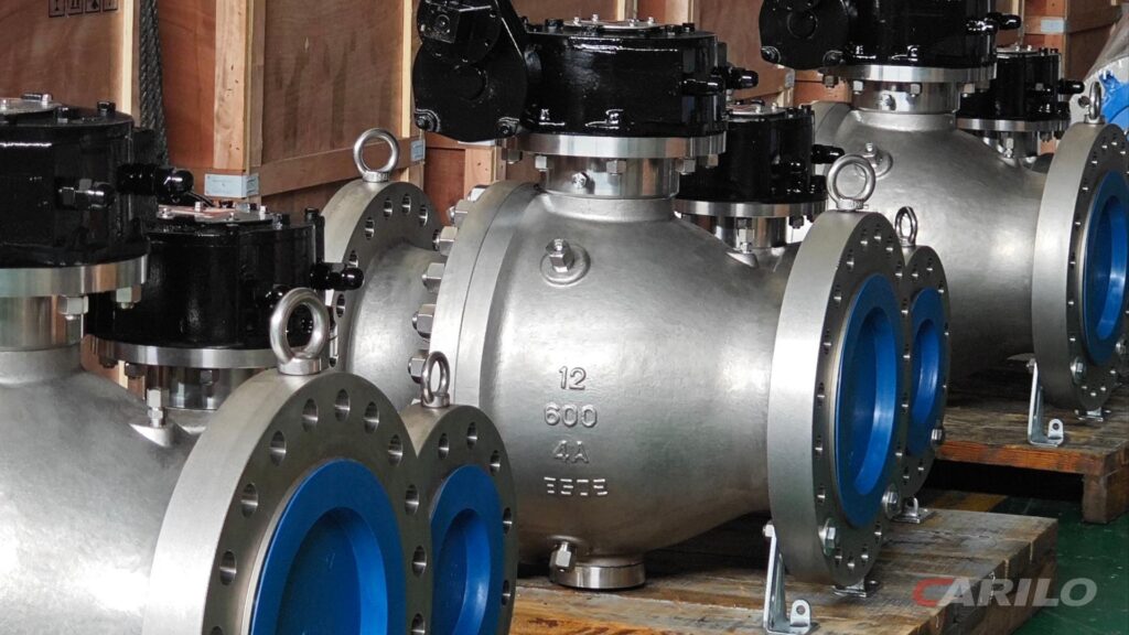
When selecting a ball valve for corrosive media, the valve body should use Hastelloy C-276 to withstand strong acids above 50% concentration, while the seat should be made of PFA-lined material rated to 260°C to ensure zero leakage. It is also recommended to test stem torque once every 5,000 open-close cycles to maintain long-term reliability. Corrosion Resistance Forms of Corrosion Once water contains as little as 500 ppm chloride ions, the wall of an ordinary 304 stainless steel pipe can develop tiny pits about 0.15 mm deep after just 72 hours of continuous exposure. Water trapped inside those pits cannot escape, and the pH can quickly drop to around 1.5. Large amounts of iron ions dissolve into the water, and a sound pipe wall can be fully penetrated within weeks. In chemical plants, material testing is often done by immersing metal coupons in a 6% ferric chloride solution. For every 5°C increase in water temperature, the material’s resistance to localized dissolution drops sharply, and the protective threshold quickly collapses. The joint where the metal ball meets the plastic seat inside a ball valve is one of the most failure-prone areas. Liquid gets trapped in stagnant gaps only 0.02 to 0.1 mm wide. In this dead zone, oxygen is depleted, and the oxide passivation film on the metal surface can no longer remain stable. Dead edges beneath flange gaskets Contact surfaces between soft seats and metal components V-ring grooves at the bottom of the stem Threaded joints where pipes are tightly screwed together In chemical plants, material selection often focuses on the critical crevice corrosion temperature. 2205 duplex stainless steel begins to fail at around 20°C in standard test solutions. By contrast, 254SMO super austenitic stainless steel, with 6.1% molybdenum, raises that threshold to above 35°C. The high heat from welding can turn good steel into scrap. When temperature stays in the 450–850°C range, the carbon in the steel combines with chromium, the element responsible for corrosion resistance. Large quantities of chromium carbide crystals then precipitate along grain boundaries. Legacy-standard fittings with 0.08% carbon Rough castings that have not been solution annealed at 1040°C Weld joints repeatedly built up with excessive current Once chromium content at the grain boundaries falls below 12%, corrosion resistance is effectively lost. Experienced buyers often specify 304L or 316L ultra-low-carbon grades instead, keeping carbon below 0.03% by weight so that destructive chromium carbide precipitation is minimized. When slurry moves through a pipe at speeds above 3 m/s, it becomes disastrous for valves. The freshly formed anti-corrosion film on the metal surface, only about 0.01 microns thick, can be stripped away by sand in less than half a second. The exposed metal then suffers both acid attack and constant abrasive wear. To address this, plants often use supersonic spraying to apply a 0.25 mm tungsten carbide coating to the surface of the valve ball. With a Vickers hardness above HV1200, the coating can withstand severe cutting wear even in pipelines carrying heavy sand-laden media. Serious problems also occur when dissimilar metals are fastened together and immersed in saltwater. In seawater lines, a titanium alloy valve bolted to an ordinary carbon steel flange can develop a natural potential difference of about 0.8 volts. Stainless steel seawater pipes connected to brass fittings Titanium plates touching steel supports near pickling tanks Pipe sections buried in high-salinity alkaline soil The carbon steel, acting as the anode, corrodes 3 to 5 times faster than normal. If the titanium alloy has a large surface area and the carbon steel a small one, the weaker steel section can perforate within days. For this reason, installers must place a 3 mm rubber isolation gasket between the flanges before tightening the bolts. Condensing lines at the top of refinery towers often crack without warning. The pipes operate under about 2.5 MPa of internal pressure while also carrying cooling water containing 30–50 ppm chloride ions. Under the microscope, the cracks appear as branched, tree-like fractures running through the metal grains. From the outside, the pipe may show no visible thinning or deformation. If the water temperature rises from 50°C to 80°C, the growth rate of these branched cracks can multiply. Natural gas wellheads are constantly exposed to high concentrations of hydrogen sulfide. When acidic water reacts with iron, it releases atomic hydrogen. These tiny hydrogen atoms force their way into crystal lattice gaps up to 0.5 mm deep within the steel. Once dozens of hydrogen atoms collect in microscopic voids, they combine into hydrogen gas pockets. The expansion pressure can reach thousands of atmospheres, creating stepped blisters inside the steel plate. Factory qualification testing therefore requires immersion in acidic water at pH 2.7 for 96 hours without cracking. Material Selection On cooling-water circulation lines around chemical plants, WCB carbon steel ball valves are common. Once ambient relative humidity exceeds 70%, an unprimed cast steel surface can oxidize by about 0.01 mm per month. If the line carries dilute sulfuric acid at a concentration as low as 0.05%, the inner wall can develop pinhole corrosion the size of a fingernail in less than three days. Switching to CF8 cast 304 stainless steel, which contains about 18% chromium and 8% nickel, can solve this in some services. In nitric acid below 65% concentration at room temperature, the pipe wall can remain intact for five years without scaling. But if it is mistakenly installed in a hydrochloric acid line, yellow-brown acid-wash bubbles can appear on the surface within two hours. CF8M, which corresponds to 316 stainless steel, usually costs about 30% more per ton than 304. That extra cost mainly comes from the added 2–3% molybdenum. In coastal refinery systems handling seawater with about 30,000 ppm salinity, that molybdenum helps protect the flow passage from rust formation. Under the high-pressure, high-salinity conditions of offshore drilling platforms, ordinary stainless steel is no longer sufficient. 2205 duplex stainless steel uses a roughly 50/50 austenite-ferrite microstructure, giving it a yield strength of about 450 MPa, more than twice that of 316 stainless
Which Valve Fits Your Pipeline Better:Industrial Ball Valve vs Butterfly Valve? | pressure resistance, installation space, operating torque
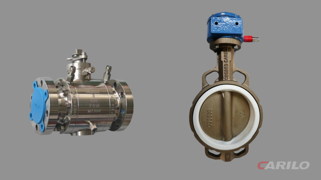
Industrial ball valves can handle pressures of up to 1,000 bar, but they require high operating torque and take up more space. Butterfly valves save a great deal of installation space, and their operating torque is only about one-third that of ball valves, but their pressure rating is usually limited to within 25 bar. For large-diameter pipelines in confined spaces, butterfly valves are the practical choice. For high-pressure service requiring tight shutoff, ball valves are preferred. Both can be opened or closed quickly with a 90-degree turn of the handle. Pressure Resistance Under the ASME B16.34 design standard, trunnion mounted ball valves use thick-wall forged or cast steel bodies and can operate reliably in ultra-high-pressure pipelines up to Class 2500 service, approximately 414 bar / 6,000 psi. Concentric butterfly valves are limited by their rubber-seated disc design, with pressure capacity generally capped at Class 150, or about 20 bar / 285 psi. Triple-offset metal-seated butterfly valves raise that limit to Class 600, around 100 bar / 1,480 psi. For oil and gas transmission pipelines above this pressure range, industrial ball valves are mandatory. Load Distribution When pipeline designers lay out the cramped deck areas of a North Sea FPSO, every inch of space carries a clear cost. A look at the face-to-face dimensions defined in ASME B16.10 makes the physical difference obvious. An NPS 12 (DN300) Class 150 flanged ball valve has an overall face-to-face length of 356 mm. In a crowded pipe rack, that extra length often intrudes directly into the maintenance access of adjacent equipment. A wafer butterfly valve looks remarkably slim by comparison. Under the same dimensional standard, a 12-inch butterfly valve is compressed to a body thickness of just 78 mm. Sandwiched between two pipe flanges, it takes up less than one-fifth of the axial space required by a ball valve. When 50 parallel lines are installed on a chemical plant pipe rack, that difference in thickness can reduce the overall rack width by nearly 2 meters. The face-to-face length of an 8-inch flanged ball valve is 292 mm. An 8-inch lug butterfly valve is only 60 mm thick. A more compact piping layout can reduce carbon steel pipe consumption by as much as 15%. A shorter flow path also slightly reduces the valve body’s heat-radiating surface area. Axial length is only part of the story. Industrial valves are large, heavy steel components that demand three-dimensional space. A 16-inch (DN400) large-diameter ball valve can be extremely heavy. A two-piece cast steel ball valve of this size can weigh as much as 850 kg. To support that mass, an independent heavy-duty structural steel support must be welded beneath it. If the pipeline undergoes just 3 mm of thermal expansion or contraction, the heavy valve body can impose several tons of lateral tearing force on the support structure. A concentric butterfly valve of the same size weighs less than 120 kg and does not need additional bottom support. Its weight is fully carried by the flange bolts at both ends of the pipeline. Installers with standard hand tools can bolt it directly into a suspended line. During retrofit work in Houston refineries, high-performance butterfly valves are often used to replace bulky gate valves and ball valves, without having to rebuild the original concrete foundations. Clearance problems are even more severe in the vertical direction. High-pressure, large-diameter ball valves require massive scotch yoke pneumatic actuators to overcome friction. The actuator cylinders project horizontally on both sides and often exceed 1.2 meters in length. When the spacing between upper and lower pipe runs is only 800 mm, those oversized cylinders can end up hard against the upper line. A rack-and-pinion actuator housing is typically about 30% smaller than a scotch yoke actuator. A 10-inch ball valve actuator often requires a separate air reservoir. The very low operating torque of a butterfly valve allows it to use a highly compact electric actuator. A handwheel-driven gearbox requires 600 mm of overhead clearance for the operator. The cylinder exhaust silencer takes up an additional 50 mm of external space. When the internal PTFE seat of a three-piece ball valve needs replacement, the center body section must be removed entirely. At least 200 mm of loosening space must be reserved on both sides of the line. With a top-entry ball valve, maintenance personnel must also leave clear operating space directly above the valve so a chain hoist can lift the solid steel ball, which may weigh hundreds of kilograms, straight out of the body. Routine maintenance on a butterfly valve is much easier. Technicians simply loosen several stud bolts on the wafer flanges, pry the flanges apart by about 10 mm, and slide the entire butterfly valve out in parallel like a drawer. In a cramped underground water treatment pump room, two workers with a small hydraulic jack can remove a 24-inch rubber-lined butterfly valve in half an hour. The butterfly valve’s extremely compressed profile also comes with an inherent physical drawback. When the disc is fully open, its edge still projects beyond the valve body and into the upstream and downstream pipe bore. In an NPS 10 line, the disc can protrude by nearly 50 mm. If a dual-plate check valve is installed within that same 50 mm zone, the disc can strike the internal components of the check valve violently as it opens. Buried natural gas networks offer a very different perspective on space. In Alberta’s winter heating network, API 6D fully welded ball valves are buried as deep as 3 meters below the frozen ground. They require no large and expensive above-ground valve chambers. Only a long extension stem reaches the surface. A piece of equipment that would normally occupy dozens of cubic meters above ground is reduced to a surface operating post no larger than a road sign. A fully welded valve body eliminates the space otherwise needed for bolted flange joints. The outer sleeve of the extension stem is filled with polyurethane foam to prevent freezing. Only a
Industrial Ball Valve Applications in Oil and Gas Pipelines | high pressure, fire safe design, operational safety
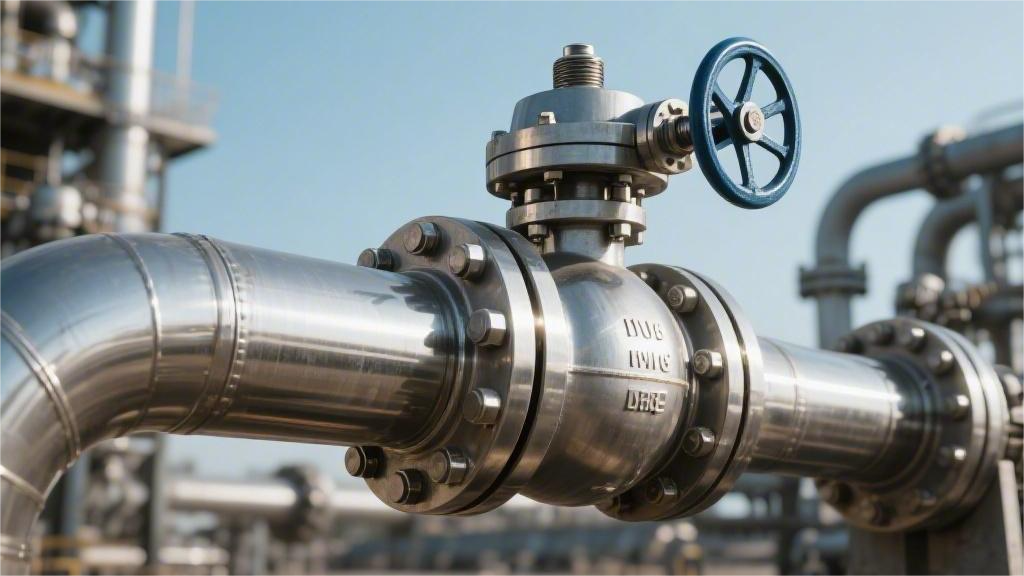
Industrial ball valves for oil and gas pipelines can withstand pressures of up to 10,000 PSI. The handle must be turned smoothly through 90 degrees to prevent water hammer in the pipeline system. For operational safety, the valve uses an anti-blowout stem design and complies with API 607 fire-safe standards. If a fire destroys the non-metal soft seat, the secondary metal seat will quickly seal against the ball, effectively stopping high-pressure oil and gas leakage. High Pressure High-pressure pipeline ball valves are rated for ASME Class 900 to 2500 service. Under API 6D, the valve body must withstand a hydrostatic test at 1.5 times its rated pressure. In natural gas export pipelines in the Permian Basin, normal operating pressure typically stays between 10.3 MPa (1,500 psi) and 14.8 MPa (2,150 psi). When the line size reaches 42 inches, the one-way axial thrust acting on a trunnion-mounted ball can exceed 500 tons. Engineering projects typically use ASTM A105 or A350 LF2 forged steel to build split-body valve housings, with a minimum wall thickness of 85 mm to resist long-distance pipeline stress and the expansion load of the internal medium. Trunnion Support On the 48-inch Trans-Alaska crude oil pipeline, winter temperatures often fall below -40°C, while daily operating pressure inside the line remains around 1,180 psi. Under those conditions, the force pushing against a closed ball approaches 1,500 tons. In a standard floating ball valve, that massive one-way thrust would drive the ball straight into the downstream PTFE soft seat, instantly crushing the seal and shutting down the entire line. To absorb that 1,500-ton destructive load, engineers add high-strength forged cylindrical shafts—trunnions—to the top and bottom of the ball and lock them firmly into bearing supports inside the valve body. The enormous fluid-induced thrust is transferred entirely into these two oversized metal shafts. As a result, the upstream and downstream seats only need to carry the initial spring preload. The hardware supporting this system is governed by strict engineering specifications: Upper journal size: Under API 6D, the upper trunnion diameter for a 48-inch ball typically reaches 350 mm. Pressure-bearing material: 17-4PH precipitation-hardening stainless steel is used, with yield strength above 1,000 MPa. Surface reinforcement: The journal surface is coated with a 0.15 mm layer of tungsten carbide to resist severe friction. Assembly process: The fit tolerance between shaft and bearing is tightly controlled at 0.05 to 0.08 mm, and the lower support plate must be press-fitted using 50-ton hydraulic equipment. With tolerances that tight, ultra-low-friction bearings are essential. Many valves used in North American gas transmission systems are fitted with metal-backed DU plain bearings. These use a steel shell with a porous bronze sintered layer and a surface layer of PTFE and lead. This self-lubricating design delivers a friction coefficient of only 0.04 to 0.06. Thanks to that extremely low friction, even under Class 1500 pressure conditions, a solid 8-ton ball can still be rotated smoothly through 90 degrees by a pneumatic actuator with less than 90,000 N·m of torque. In harsh environments such as Saudi Arabia’s Ghawar oilfield, where high chloride concentrations and trace hydrogen sulfide are present, the lower support trunnion is replaced with Inconel 625 nickel alloy to prevent intergranular corrosion. In Italian manufacturing plants, these metal parts—often weighing over ten tons—are assembled in temperature-controlled workshops maintained at 20°C to eliminate dimensional error caused by thermal expansion and contraction. Operators use CNC vertical lathes to precision-grind the outer surface of the ball, and roundness error is strictly limited to less than 0.02 mm. Before shipment, the finished valve is sent to an underground pressure-testing bunker, where the cavity is filled with pure water containing a rust inhibitor. During the test, pressure is raised to 1.5 times the rated value and held for 120 minutes, while acoustic sensors mounted on the exterior monitor for high-frequency leakage noise. After passing inspection, the valve is coated with a 300-micron zinc-rich epoxy primer and loaded onto a flatbed trailer for transport to the Port of Houston. Metal-to-Metal Sealing At the Thunder Horse deepwater platform in the Gulf of Mexico, wellhead operating pressure remains around 15,000 psi. The produced crude contains a high concentration of quartz sand. Under that extreme pressure differential and severe abrasion, PTFE soft seats cannot survive more than 72 hours before they plastically deform and tear apart. In the field, engineers remove the damaged soft seals and replace them with all-metal sealing components as the fluid barrier. The seat ring base is forged from ASTM A182 F51 duplex stainless steel, raising its yield strength above 450 MPa. Bare stainless steel surfaces cannot endure prolonged sand erosion, so surface hardening is mandatory. In valve manufacturing workshops in Texas, robotic arms carry out HVOF (High Velocity Oxygen Fuel) spraying. Aviation kerosene and high-purity oxygen burn together to generate a 3,000°C flame stream, which propels tungsten carbide (WC) powder at Mach 2.5 onto the ball and seat surfaces. The powder particles flatten instantly on impact and form a dense mechanically interlocked coating on the metal substrate. The tungsten carbide layer is controlled within a physical thickness of 0.25 to 0.35 mm. Its internal porosity is forced below 0.5%, cutting off the corrosion path through which high-pressure sour gas could otherwise penetrate the base material. Coating Chemistry Spray / Overlay Process Rockwell Hardness Applicable Pipeline Scenario Coating Porosity Tungsten Carbide (WC-Co) HVOF 68–72 HRC Canadian oil sands pipelines with heavy quartz sand abrasion < 0.5% Chromium Carbide (Cr3C2-NiCr) HVOF 60–65 HRC North Sea high-pressure, high-temperature sour gas wellheads (350°C) < 0.8% Stellite 6 PTA Plasma Powder Welding 40–45 HRC High-pressure, strongly acidic crude service in Alaska pipelines 0% (fully metallurgically bonded) Once spraying is complete, the cooled tungsten carbide surface is as rough as sandpaper. A CNC grinder fitted with a diamond wheel begins rough grinding to remove excess material. The geometric deviation of the ball’s outer diameter is quickly corrected to within 0.05 mm. The ball and the two metal seats must achieve an exceptionally high level of physical contact. These three
Key Factors to Consider Before Buying an Industrial Ball Valve | connection type, operating pressure, application media
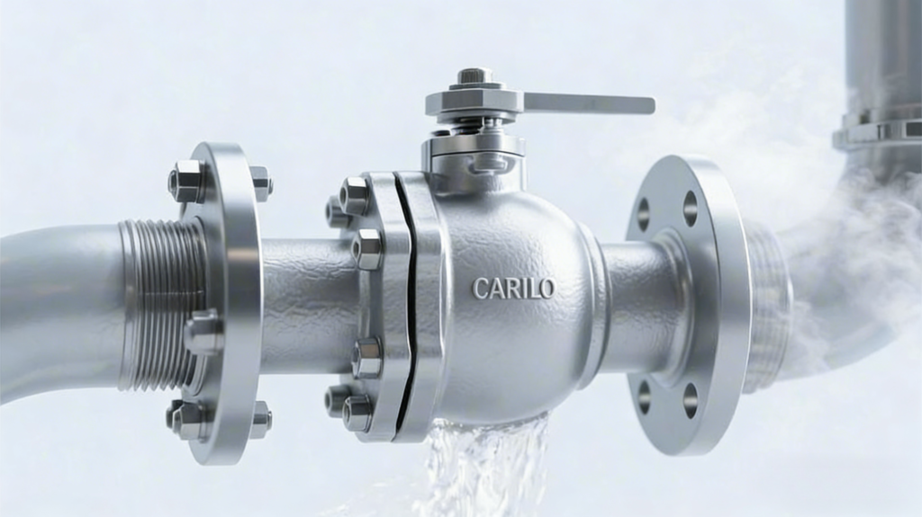
For highly corrosive media, 316L is recommended with a PTFE seat rated to 200°C. Check the operating pressure carefully. If system pressure exceeds 10 MPa, threaded connections must be avoided and replaced with flanged connections to prevent leakage. In actual operation, the handle must be turned a full 90 degrees in one motion to either the fully open or fully closed position. Never use the valve half-open for throttling, as this can cause erosion damage. Connection Type ASME B16.5 flanged connections cover pressure classes from Class 150 to Class 2500, suit pipe sizes above 2 inches, use bolted fastening, and allow the entire valve to be removed. ASME B1.20.1 NPT tapered pipe threads are limited to piping 2 inches and below, with a maximum pressure rating of 1000 PSI. ASME B16.25 butt-weld connections fuse the ends directly to the pipe wall, withstand service conditions up to 600°C, eliminate external leakage paths, and cannot be removed without damage once assembled. Tri-Clamp connections meet 3A sanitary standards, with an internal polish of Ra below 0.4 μm. They are secured with clamps and are ideal for daily tool-free disassembly and CIP cleaning. Flanged Connection In North American chemical plants, the most common pipeline connection is the ASME B16.5 flange. Pipe sizes from 2 inches to 24 inches are joined using round metal flanges with a full ring of bolt holes. A gasket is sandwiched between the two flanges, and workers tighten the nuts with large wrenches. Any two flanges machined to the same North American standard will line up with exact bolt-hole alignment. A valve marked Class 150 is completely different in size from one marked Class 300. A 4-inch Class 150 ball valve flange end has 8 bolt holes. At Class 300, the flange becomes 0.38 inches thicker and the bolt count jumps to 12. If the pressure class is wrong, the first bolt will not even go in on site. RF (raised face) is the sealing-face type most commonly purchased by factories. On Class 150 and Class 300 RF flanges, the raised face is 1/16 inch high. At Class 600 and above, the raised face height is machined to 1/4 inch. The purpose of the raised face is to concentrate bolt load onto the narrow sealing area of the gasket. The lathe machines concentric or spiral fine grooves into the sealing face of an RF flange. ASME specifications strictly control this phonograph-like surface finish to 125 to 250 microinch AARH. When you drag a fingernail across the face, it sounds like the rough friction of an old vinyl record. If the metal surface is too smooth, it cannot grip the rubber gasket in the middle. Stainless steel pipelines are usually fitted with CGI spiral wound gaskets. Alternating layers of 304 stainless steel strip and flexible graphite are wound into a ring, with a solid carbon steel centering ring around the outside. Workers compress a 0.175-inch gasket down to 0.125 inches. The black graphite is forced into the grooves on the flange face to seal off every gap. On old cast-iron piping in water plants, the removed valves are typically FF (flat face) flanges. If a new RF raised-face steel ball valve is forced onto an old FF cast-iron flange, the result is disastrous. At only 80 ft-lb of torque, the raised face loads the brittle cast iron unevenly and can crack the flange in half on the spot. Pressure Class Standard Raised Face Height Matching Gasket Type Common Pipe Material Class 150 1/16 in 1/8 in non-asbestos sheet A106 B carbon steel pipe Class 300 1/16 in PTFE envelope gasket 316L stainless steel pipe Class 600 1/4 in CGI spiral wound gasket Monel alloy pipe When pressure on long-distance natural gas transmission lines exceeds 1500 PSI, RF raised faces are no longer enough. The line switches to RTJ (ring-type joint) flanges. A trapezoidal groove 0.25 inches deep is machined into the flange face, and an octagonal soft iron ring is fitted into the groove. Once the bolts are tightened, the soft iron deforms plastically and fills the groove completely. Flanges should be fastened with ASTM A193 B7 high-strength studs and matching A194 2H heavy hex nuts. B7 bolts have a yield strength of up to 105,000 PSI. Ordinary hardware-store steel bolts will stretch under 2000 PSI water pressure like pulled noodles. Pipefitters use calibrated torque wrenches and never strike a standard wrench handle with a ten-pound hammer. On a 4-inch Class 150 flange with eight 5/8-inch bolts, the specified torque is 120 ft-lb. Tightening is done in a crisscross star pattern in three passes: 30, 60, then 120 ft-lb. Even slight uneven loading will cause leakage during hydrostatic testing. ASME B16.10 fixes the Face-to-Face dimension of the valve. If an old 6-inch ball valve removed from the line measures 15.5 inches end to end, any new 6-inch ball valve from stock made to the same standard will also be exactly 15.5 inches long. A valve weighing hundreds of pounds can be installed between two pipe ends without any pipe modification or welding. European plants use EN 1092-1 flange standards. If you try to fit an American Class 150 valve onto a European PN16 pipeline, it will not match. At 3 inches, the PN16 bolt circle diameter is 160 mm, while Class 150 is 152.4 mm. With a 7.6 mm offset, the bolts simply will not pass through the opposing flange holes. Japanese packaged equipment often comes with JIS B2220 flanges. JIS 10K flanges have their own thickness and drilling dimensions. If workers force an American gasket into a JIS flange connection and tighten it, the pump may reach only 150 PSI before water sprays three meters from the side of the eccentrically crushed gasket. When buying flanged valves, the load-bearing capacity of the pipe supports must be checked. An 8-inch threaded bronze valve weighs under 50 lb. Replace it with an 8-inch Class 600 cast steel flanged ball valve with two heavy flanges, and the scale jumps to 450 lb.
