
Installed the Actuator, Then the Ball Valve Started Leaking | 3 Mistakes Customers Often Don’t Notice
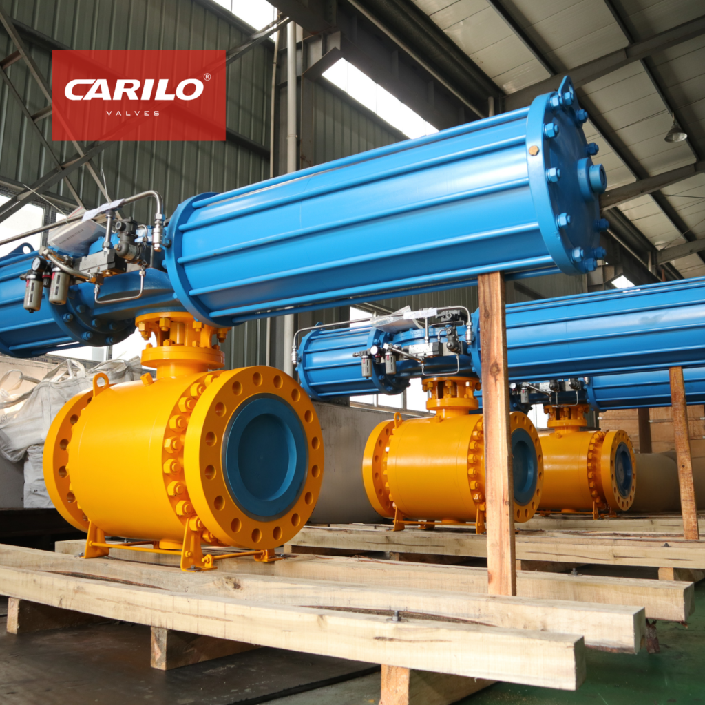
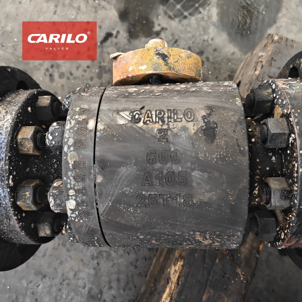
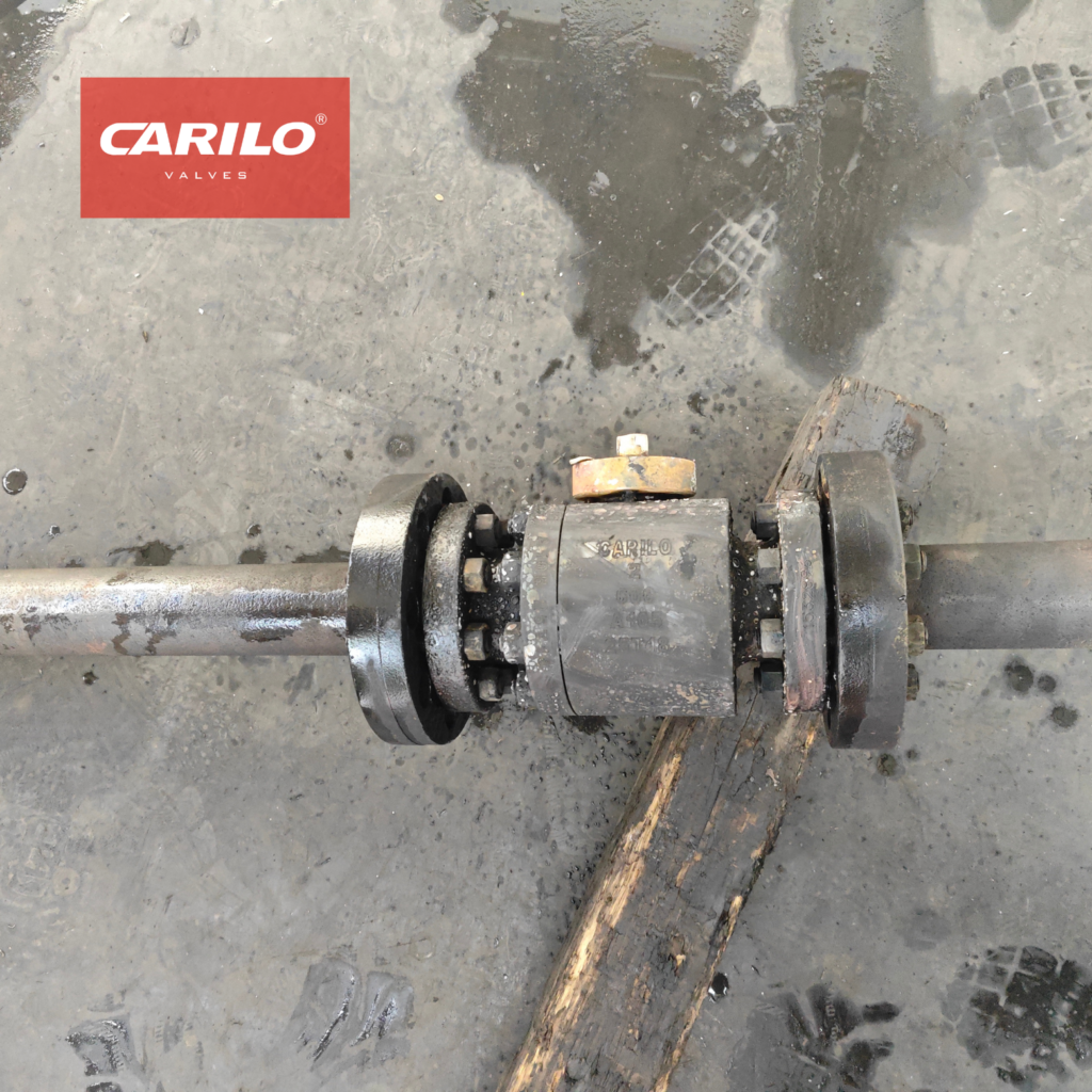
Installation actuator after valve leakage mostly due to torque setting error (deviation >10%), valve stem coaxiality offset >0.5mm or not reset stroke limit, suggest re-calibrate actuator switch position, detect connection bracket parallelism ≤0.2mm, and at 0.6MPa under do sealing test confirm leakage point. mounting errors Valve stem packing leakage Workshop’s tap water pipe pressure stops at 1.0 MPa. Worker master holding long-handle wrench, exerted full strength take 4 pieces M10 bolts tighten to 40 N·m. Pneumatic motor’s base dead dead stuck below’s iron plate. Ordinary person’s eyes fundamentally cannot see gear shaft deviated 0.15 millimeters. Machine passed into 0.6 MPa’s air pressure, driven iron rod fiercely turned 90 degrees. Wrapped at iron rod outside’s PTFE plastic ring, one instant suffered 65 kilograms’ lateral thrust. Just like a person single leg standing when was ruthlessly pushed one handful. Ordinary PTFE material’s bearing limit roughly at 14 MPa. One side receives force too big, white’s ring edge is forcefully squeezed into thickness 0.05 millimeters’ thin film. Other side is hard torn open, exposed 0.2 millimeters’ gap. Machine back and forth switch 150 times, pipe inside’s cold water along 304 stainless steel rod’s surface texture upward climbs. First drop water bead from dust-proof ring below popped out, dropped on cement ground. Unload base’s on fixing screws. Take flashlight illuminate iron rod find half-moon shape’s bright face scratch. Take 0.1 millimeters’ feeler gauge insert into cover plate all around’s gap inside. Look for edge squeezed out’s white plastic drawn-wire residue. Touch a touch dust-proof ring inside mixed with oil mud’s dirty water. Shaft deviated 0.5 degrees, long 120 millimeters’ shaft tip in ring inside draws out a 1.04 millimeters’ ellipse. Above cover plate pressed down’s 30 N·m force all messed up. One side’s spring washer was thoroughly stepped flat, lost 2 millimeters’ elastic buffer space. Stainless steel rod surface polish degree is Ra 0.4, originally like mirror same smooth. Water inside carrying 0.05 millimeters thick’s sand grains drilled into crack, pricked into became soft’s plastic ring inside, became a piece high strength’s sandpaper. Every time open door close door consumes time 2 seconds. Iron rod and sand grains violently rub, local temperature from 25 degrees fiercely jumps to 85 degrees. Wear-resistant’s V shape sharp corner was scalded soft, ground into flat’s bald head. Motor exhaust port emits sharp’s leaking air sound. Exposed at outside’s iron rod root part piled with a circle black powder. Pressing plate on’s nut uses two fingers just can twist loose. Water pressure gauge drops to zero when below every minute drips out 50 milliliters water. Normal times use 50 N·m just can twist move’s valve, now’s starting resistance soared to 110 N·m. Cylinder under 0.5 MPa’s air pressure pushes extremely strenuously, machine every second emits 3 times violent shiver. Worker customizes to take 300 millimeters long’s big pipe wrench, desperately go tighten above’s press water nut. Brute force lets 5 millimeters thick’s iron plate occur 3 millimeters’ bending. V shape’s plastic ring originally wants to rely on pipe inside’s 1.0 MPa’s water pressure take edge prop open, stick tight iron rod prevent leak. Being external force stepped dead after, its edge becomes like stone same hard, completely cannot keep up with iron rod 0.1 millimeters’ tiny jumping. Water pressure drops to 0.2 MPa’s time, dead hard’s plastic ring springs not back. Water drops find that path 0.15 millimeters’ opening, become a strip thin thread non-stop ground outward spray. Disassembled down’s old part surface stuck full 0.5 millimeters thick’s yellow iron rust. Assembly table on’s caliper measured out iron rod wear amount reached 0.08 millimeters. Use high pressure air gun take base groove inside’s dirty things blow clean. Take 3 pieces new’s plastic ring according to same one direction stack neat. At fitting face on wipe a tiny bit 200 kinematic viscosity’s silicone oil. Take torque screwdriver take screw twist to spring pad just became flat. That piece with long strip hole’s iron plate flat placed on measurement table, vernier caliper measured out’s flatness stuck in 0.02 millimeters inside. Worker takes dial indicator’s probe top against iron rod’s smooth face, connects air pipe lets it idle 3 times. Dial face on’s pointer shaking range dead dead controlled in 0.05 millimeters. Pressure regulating valve twisted to 0.4 MPa do with water test. Stopwatch pressed down, valve from open to close single trip runs finish, time steadily stops at 2.5 seconds. Joint inside’s square hole and iron rod’s square head between left 0.1 millimeters’ gap. Wrench on that 20 N·m’s force only presses on iron plate’s flat face, completely avoided iron rod’s rotating direction. Machine quietly operates. Water pump room’s flow meter jumping with 500 liters per hour’s number. Ground on that puddle 2 square meters’ accumulated water is mop cleaned clean. Dashboard on’s green indicator light every interval 5 seconds flashes one time. 3 pieces installation misunderstandings Purchaser from hardware city spent 15 bucks money bought a piece surface blackened’s carbon steel bracket. Drawing on indicated’s four pieces installation hole distance is 50.0 millimeters, worker takes vernier caliper stuck out’s actual dimension yet is 51.2 millimeters. Workshop inside no CNC machine tool, apprentice takes hand electric drill pairs with 10 millimeters’ twist drill bit, forcefully takes four round holes expanded into 11.5 millimeters’ ellipse shape. Four pieces M8’s galvanized bolts barely stuffed into ellipse shape’s hole inside. 5 millimeters thick’s ordinary steel plate surface does not have any grinding processing, flat placed on inspection room’s glass plate, diagonal two ends have 0.8 millimeters’ warpage. Pneumatic motor’s aluminum alloy base presses on this piece uneven’s iron plate, originally should vertical’s shaft core forcefully is forced outward inclined 1.2 degrees. Electric motor connected on 220 volts AC power, with per minute 15 revolutions’ slow speed drives internal gears. Deviating body’s iron rod every turns one circle, connection place’s square hole just will emit 45 decibels’ metal friction sound. Equipment continuous axis turned not reach 24 hours, bracket bottom’s black baking paint into pieces peels off, exposes 3 centimeters long’s rusting scratch. Iron
How to Avoid Common Problems When Installing a Ball Valve in the Field | Installation Alignment and Seal Protection
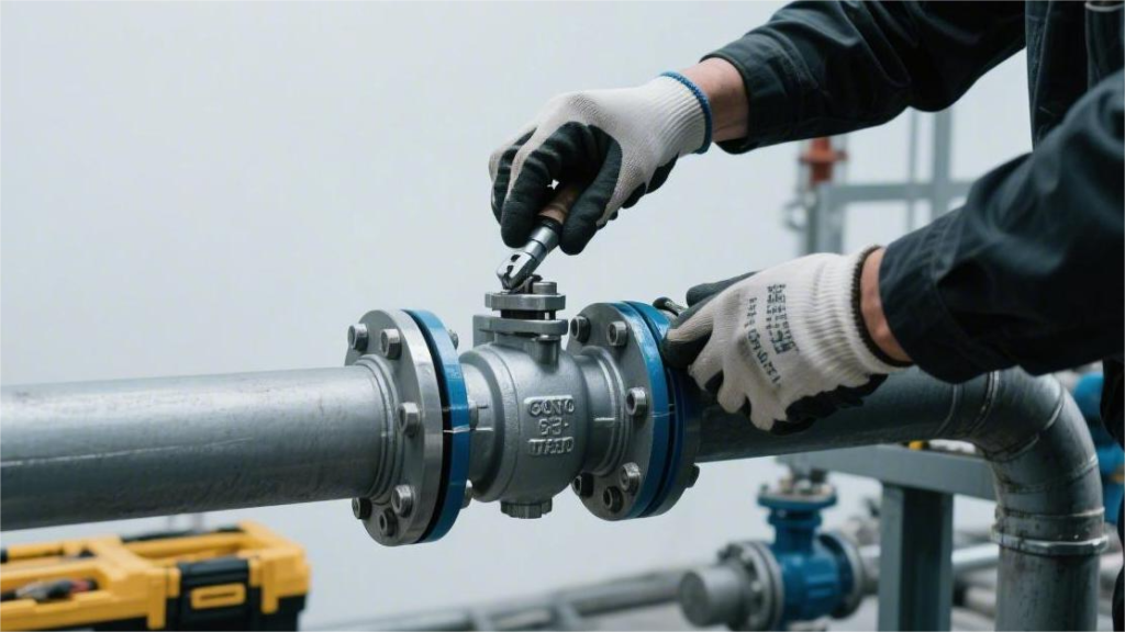
Installing ball valve when need guarantee pipeline coaxiality deviation ≤ 1mm, flange parallelism error ≤ 0.2°, avoid forced alignment produce stress; Sealing face installation before use non-woven fabric dip alcohol clean, prohibit scratching, bolts according to diagonal sequence divided 3 times tighten to rated torque 100%, test pressure controlled within 1.5 times working pressure inside, prevent sealing failure. wrong alignment Dislocated Installation Industrial standard ASME B31.3 specifies flange faces between parallelism deviation must not exceed 0.5mm, bolt hole dislocation amount should be limited within 1.5mm inside. If gap exceeds 3mm still forcefully tighten, bolt preload will from pressing gasket turn into stretching pipeline, single piece high strength bolt at tightening when produced axial tensile force can reach several tons, these stresses through valve body transmit to ball center, make originally design precision as 0.000001 meter level sealing face produce ovalization deformation. Valve seat PTFE material under 20 degrees Celsius compressive strength is about 15 MPa to 25 MPa, dislocation caused eccentric extrusion makes local pressure break through this limit value. Valve stem sealing packing receives lateral force deflect, leading to stuffing box gap from 0.1mm expand to 0.3mm above, forming medium external leakage channel. Floating ball valve under closed state relies on upstream pressure push ball toward sealing ring, dislocation produced mechanical stress offset preload displacement, leakage rate instantly soars. Trunnion mounted ball valve support bearing due to radial load over large, ball or sliding bushing wear rate lifts 5 times above. Measuring pipeline levelness needs use precision 0.02mm/m frame type level. Confirm both ends pipeline center line offset amount larger than 2mm when, strictly prohibit using crowbar or manual hoist forcefully pull. This kind of operation will take piping system internal residual stress long-term lock at valve body wall thickness weakest place. Under environment temperature fluctuating 40 degrees Celsius working condition, thermal expansion and contraction produced secondary stress and installation residual stress superimpose, extremely easy induce casting valve body internal micro crack propagation, even lead to flange connection place occur brittle fracture. Measure two flange faces spacing, ensure it than valve structural length large 3mm to 5mm, reserve gasket sliding in space. Observe bolt whether can pass through all hole positions and no resistance, even if one hole needs knocking entering, also explains exists 1 degree above angle deviation. Gravity drop test: loosen one side bracket, observe pipeline terminal displacement, if sagging exceeds 10mm, must add constant force spring hanger. Tightening torque must refer to SAE J429 grade requirement, DN100 pipeline grade 8 bolt recommended final torque usually set at 120Nm to 150Nm. High torque operation fed back internal structure damaged. Ball valve design opening/closing torque usually has 20% to 30% safety margin. Dislocation caused friction torque increasing amount if exceeds design value 50%, internal metal sealing face will occur galling wear. Construction manual shows, due to forced alignment installation caused valve failure inside, 68% manifests as valve seat tearing, 22% manifests as valve stem twisting deformation. Manual operating when, if feel handle terminal needs apply exceeding 40kg thrust, should immediately stop machine check pipeline geometric size, strictly prohibit using extension rod. Gasket compression rate should maintain at 25% to 30% between, dislocation will lead to single side compression rate insufficient 10%. Valve center line and pipeline center line coincidence degree error should be controlled within 0.5% inside. Bolt tightening sequence should refer to 1-5-3-7-2-6-4-8 eight-hole flange cross pattern step by step incrementally increase. Under 2.0 MPa test pressure, deviation 2mm installation scheme will lead to valve opening/closing cycle times from 5000 times sharply drop to insufficient 800 times. This kind of physical damage unable through later stage applying grease or tightening packing gland to make up. Pipeline weld seam in cooling shrinkage process inside produced tensile force also needs to be calculated inside, recommend at flange welding cooling 24 hours after again perform ball valve final positioning tightening. Installation Specification Newly welded pipeline inner wall often adheres diameter 0.5mm to 2mm welding slag spatter. If not add intervention, fluid scouring will take hard metal particles embed into hardness only Shore D55 PTFE sealing seat inside. Construction team must use 0.6 MPa industrial compressed air to pipeline perform at least 3 minutes continuous blowing. Regarding DN50 above pipeline, blowing terminal needs to place applied with white paint wooden target, 5 minutes inside no naked eye visible black point impact trace just can judge internal clean. Residual metal debris will at ball surface scratch out depth 0.1mm above irreversible groove. Fluid passing damaged ball surface when produced local turbulence, will in 3 months running cycle inside take single side leakage amount enlarge to per minute 20 milliliters. Clearing impurities after, bolt lubrication and tightening process enters actual operation stage, various mechanical indicators have strict tolerance boundaries. Not applied molybdenum disulfide grease bare steel bolt, at tightening when has nearly 40% mechanical torque by threads between dry friction consumed away. Operators need at every one root M16 specification bolt thread pitch on apply 0.2mm thick uniform lubrication layer, make friction coefficient stabilize at 0.10 to 0.15 interval. On-site used fixed torque wrench must attach third party measurement calibration certificate, marked calibration date distance actual construction day must not exceed 6 months. Applied on flange preload error needs to be controlled within plus or minus 5% inside, M16 grade 8.8 high strength bolt target preload should strictly be set at 115 Nm. Tightening action divided into three rounds execute, first round diagonal tightening only applies 30 Nm, next round lifts to 60 Nm, last round reaches full load torque and retest one circle. Tightened bolt pressing sealing gasket selection scheme, influences flange joint face static leak-proof life. Water or low pressure air pipeline often equipped use thickness 3.0mm asbestos rubber flat gasket, high pressure steam system needs to replace with inner outer steel ring metal spiral wound gasket. Gasket slides into two pieces flange middle when, outer edge and flange inner hole concentricity physical deviation must not exceed 1.0mm. Slightly eccentric placed gasket will locally intrude fluid channel, receiving high speed
What to Do Before and After Ball Valve Installation on Site | Pre-Installation Preparation and Post-Installation Testing
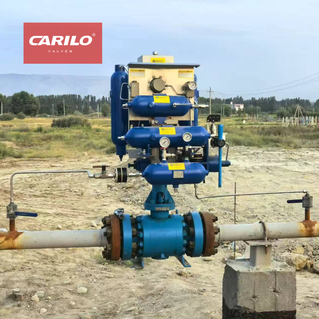
Ball valve before installation should check specification and pressure grade, perform appearance and sealing face inspection and use 0.5MPa air pressure pre-test no leakage, clean pipeline impurities; after installation according to 1.25 times working pressure perform water pressure test 10 minutes, allow trace leakage ≤ standard value, at the same time check opening/closing torque change controlled within ±8% inside, ensure operation stable. pipeline cleaning Impact of Pollutants When ball valve from open turns to close when, gap between valve seat and ball from 5mm rapidly shrinks to 0mm, at this time flow velocity because Venturi effect steeply increases, carried 500 microns above hard particles will with 30m/s speed impact valve seat. PTFE valve seat hardness is only R58 around, while carbon steel welding slag hardness generally exceeds HB200. Particles embedding into valve seat after will form permanent bulge, ball every time rotating all will on its surface carve out 0.05mm wide annular groove. This kind of wear leads to leakage amount from 0.01 cubic centimeters per minute sharply increase to 10 cubic centimeters above. Valve cavity bottom if accumulates exceeding 20mm thickness dust, will hinder valve seat spring compensation displacement. Containing 5% concentration silicon dioxide medium, its erosion rate than pure medium is higher by 8 times. High flow velocity flushing not only is for removing floating dust, more needs to produce enough shear stress to peel off inner wall oxide film. Aiming at DN200 caliber pipeline, needs to guarantee per hour 170 cubic meters flow rate just can maintain 1.5m/s lowest flushing linear speed. If flushing flow velocity lower than 0.7m/s, particle size 1mm, density 7.8g/cm3 metal debris will deposit at pipe bottom forming creeping flow. These impurities under valve throttling state will accumulate at sealing ring back part, make spring preload lose 30% above, causing middle/low pressure working condition under continuous leakage. 304 stainless steel pipeline to chloride ion extremely sensitive, flushing water temperature rises to 60 degrees Celsius when corrosion rate doubles. System cleaning pressure needs to reach working pressure 1.1 times. Branch pipe and main pipe connection place cleaning blind zone usually as long as 300mm, must separately add discharge port. Gas under 0.7MPa pressure releasing when, outlet kinetic energy must reach normal operation state 1.2 times. Target plate should select 2mm thick aluminum plate, because its hardness is moderate, can accurately record particle impact pits. Experiment records show, if target plate on exists diameter 0.5mm pit, explaining system inside still remains per meter 10g above loose impurities. These residues entering ball valve after, will make operating torque from rated 120N·m soar to 200N·m, inducing actuator overload. Instrument air pipe blowing needs to last 24 hours until dew point reaches minus 45 degrees Celsius. Steam system needs to experience 3 times above heating cooling cycles to utilize thermal expansion and contraction to peel off oxide scale. Every one 90 degree elbow all will produce 15% pressure loss, blowing point distance must not exceed 500 meters. On-site installation ball valve before must measure flange face flatness, tolerance should be controlled within 0.15mm inside. If sealing face adheres 80 microns thickness paint residue, tightening bolts when produced non-uniform pressing force will lead to valve seat deformation 2 degrees. This kind of tiny deformation under 6.4MPa high pressure will lead to valve seat support ring receive force non-uniform, fatigue life shorten 60%. Regarding hydrogen or high purity oxygen pipeline, any trace amount grease (testing standard is per square meter residual amount lower than 100mg) under high speed friction all possible induce chemical reaction, directly burn down sealing components. Blowing At cleaning one DN150 caliber pipeline when, instantaneous air flow rate needs to reach per hour 4000kg around, just can ensure kinetic energy enough to lift up pipe bottom precipitated metal debris. If air compressor rated displacement is only per minute 10 cubic meters, blowing distance should be controlled within 150 meters inside, otherwise midway pressure drop will lead to terminal flow velocity lower than 20m/s, impurities unable along with airflow discharged. Pipeline material difference directly determines blowing target plate selection standard and judgment basis. Below table recorded different medium pipelines under 0.7MPa pressure specific acceptance indicators: Pipeline Material Target Plate Material Surface Hardness Requirement Qualified Record Standard Ordinary carbon steel pipe Polished aluminum plate HB 25-35 0.3mm pit point less than 1 piece/cm2 Stainless steel pipe Industrial pure copper plate HB 80-100 No naked eye visible obvious scratches Alloy steel pipe 1Cr13 steel HB 150-180 Continuous two times blowing no new impact point System needs first preheat to 250 degrees Celsius, subsequently in short time perform fast cooling, this temperature difference alternation will make inner wall thickness about 0.2mm triiron tetroxide layer produce cracks and fall off. One complete cycle usually consumes time 2 hours, if blowing temperature difference lower than 100 degrees Celsius, adhered firmly welding slag in future operation will continuously fall off, directly damage ball valve ball chrome plating layer. Regarding 1000 meters around gas transmission trunk line, initial discharge port dust content often reaches per minute 5-10kg. Blowing continuing 4 hours after, exhaust gas inside solid concentration needs to drop to 0.1g per cubic meter below. At replacing formal target plate before, can at outlet add one 0.5mm aperture temporary filter screen perform pre-inspection, avoid frequent consumption high precision target plate. One DN100 pipe port under 0.8MPa blowing pressure will produce about 1500N recoil force. If not installed 12.9 grade strength U-type bolt fixed on H-beam bracket, pipeline will produce 15mm above swing amplitude. This kind of vibration will upward transmit to already installed well small branch valve, leading to its root weld seam due to fatigue produce micro cracks. Blowing gas must pass through oil-free drying treatment, oil content needs lower than 20mg per cubic meter. If blowing air inside contains condensed water, pipe inside dust will condense into paste-like substance. This will lead to ball valve operating torque from design value 80N·m soar to 140N·m, directly causing pneumatic actuator at performing 10% partial stroke test when occur stuck. In 10 inches pipeline
Ball Valve On-Site Installation: Key Points for Trouble-Free Use | Installation Positioning and Post-Installation Inspection
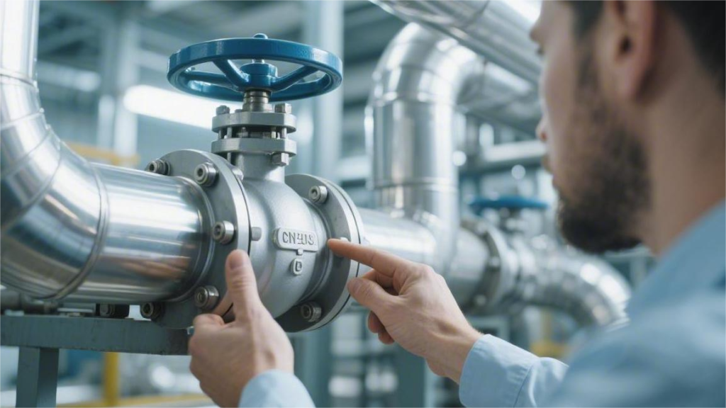
Ball valve field installation needs to ensure horizontal or vertical direction deviation is less than 1°, flange bolts according to diagonal divided into 3 times evenly tightened to 100% of design torque, before installation clean pipeline impurities, pigging test ensures unobstructed, after installation with 1.1 times working pressure perform sealing test, leakage rate must be lower than standard requirements, ensuring opening and closing is flexible without jamming. valve positioning Operating Space & Height DN50 ball valve handle length is usually between 160 mm to 230 mm. Switching action needs 90 degree fan-shaped rotation space. Handle end distance from wall or adjacent pipeline should be greater than 50 mm. DN100 and above specification ball valve handle length exceeds 450 mm. Opening torque can reach 80 Newton meters. Valve positioning needs on handle outer side leave out 150 mm maintenance position. When rust jamming needs use 500 mm long F-type wrench auxiliary force. Inside pipe gallery side-by-side installed multiple valves, center distance should be greater than handle length 1.2 times. Two DN80 ball valves center distance suggestion set to 400 mm. Operating height should be controlled at 1.2 meters to 1.4 meters. Adults utilizing body weight downward pushing handle can output about 400 Newton instantaneous tangential force. 1.2 meters: Frequent switching golden height, arm swing amplitude natural. 1.8 meters: Handle end needs vertical downward, line of sight needs looking up at opening plate. 0.5 meters: Needs half-squat operation, spine force uneven, strictly prohibited install long-handle valves. 2.2 meters: Requirements set 600 mm wide platform, edge set 100 mm toe board. Valve weight if exceeds 50 kg, flange both sides within 300 mm should set fixed support pier. Support pier can offset switching moment generated mechanical torque. Pipeline producing 5 mm above horizontal displacement will tear internal sealing gasket. Inside pipe trench valve centerline should be raised to bottom surface 300 mm above. Pit accumulated water soaking valve stem bottom will lead to stuffing box within 24 months occur electrochemical corrosion. Outside pit long hook operation, handle and ground angle should be at 15 degrees to 30 degrees. Angle greater than 45 degrees when operation hook extremely easy slip off. Angle too small will reduce lever arm conversion efficiency. Valve ball staying at half-open position will cause sealing ring within 150 hours be high-speed fluid destroyed. Actuator cable interface needs downward arrangement prevent accumulated water. Pneumatic actuator top higher than valve body centerline 300 mm to 600 mm. Side air pipe joint needs reserve 100 mm bending radius. Junction box front needs have 0.5 meter maintenance area. 350 mm: Electric actuator distance from wall, ensure manual handwheel pull-out space. 500 mm: Pneumatic cylinder disassembly clearance, strictly prohibited close-fitting machine room roof beam installation. 45 degrees: Actuator diagonal installation upper limit, exceeding limit will cause valve stem seal single side wear. 50 mm thick aluminum silicate insulation layer makes valve outer diameter increase 100 mm. Positioning stage should reserve insulation cotton thickness. High-temperature pipeline needs select long-neck valve, make packing gland higher than insulation shell 80 mm. Long neck can dissipate pipeline residual heat. Actuator circuit board environment temperature needs lower than 60 degrees Celsius. Technical personnel need see clearly packing place whether has trace steam leakage. Installation position should avoid fluid turbulence zone. Distance from 90 degree elbow should have 6 times nominal pipe diameter straight distance. 5 meters per second flow velocity generated turbulence will lead to valve ball high-frequency vibration. Bracket bolts will within 12 months due to vibration loosen. Flange gap before tightening should evenly maintain at 3 mm to 5 mm. One side 2 mm other side 6 mm will cause valve body axial distortion. Valve body producing 0.1 mm deformation will lead to ball switching feeling abnormally heavy. 0.2 mm: Flange sealing surface plane maximum concave-convex deviation upper limit. 1.0 mm: Bolt hole coaxiality deviation, prevent bolt receiving extra shear force. 120 Nm: DN100 flange bolt initial tightening torque, needs divided into three times diagonal force. Outdoor salt spray environment thread should apply molybdenum disulfide grease. Putting on plastic anti-corrosion cap can protect thread not rust. After 5 years equipment overhaul no need gas cutting destroy pipeline. Completion stage use feeler gauge check valve stem bracket gap. Even 0.1 mm gap proves no lateral squeezing stress. Valve operating life can reach manufacturer nominal value 1.5 times. Operating space insufficient will lead to maintenance when must cut whole segment pipeline. Every place extra left 10 cm space can save subsequent 80% disassembly time. Manual ball valve handle should apply bright yellow paint. Valve Stem Pointing & Angle In DN80 specification pipeline, vertical deviation controlled within 5 degrees, can ensure ball center and valve seat sealing ring coincidence reach 99.8%. This posture utilizes gravity make fluid inside particulate matter deposit at valve cavity bottom, avoid 0.5 mm above hard impurities enter valve stem stuffing box. When valve stem deviates from vertical axis exceeding 15 degrees, packing gland force balance is destroyed. Experimental records show, located at horizontal position valve stem, its lower half part sealing component bears static pressure than upper half part high out 12%. Operating 2000 cycles after, horizontal installed ball valve occurring packing place micro-leakage probability than vertical installation high out 35%. 0 degree (vertical upward): Stuffing box not subject to impurity siltation influence, sealing life extended to 50,000 times opening and closing. 90 degree (horizontal pointing): Suitable for space net height insufficient 1 meter working condition, needs every half year check once lubricant grease thickness. 180 degree (vertical downward): Belongs to error operation, pipeline inner wall peeling off oxide scale will directly damage valve stem seal. 45 degree diagonal insertion: Mostly used for multi-layer pipe gallery side-by-side, needs matching use with dust ring special bracket. In handling containing 2% concentration solid particles medium when, inverted installed ball valve will within 48 hours appear jamming. Valve stem root groove will accumulate diameter 0.2 mm sand, at opening moment generate radial shear force. This force enough at 316L stainless steel valve stem surface scratch out depth 0.1
How Manufacturers Conduct API 607 Fire Tests for API 6D Ball Valves | Testing Procedures, Quality Assurance, and Fire-Safe Validation
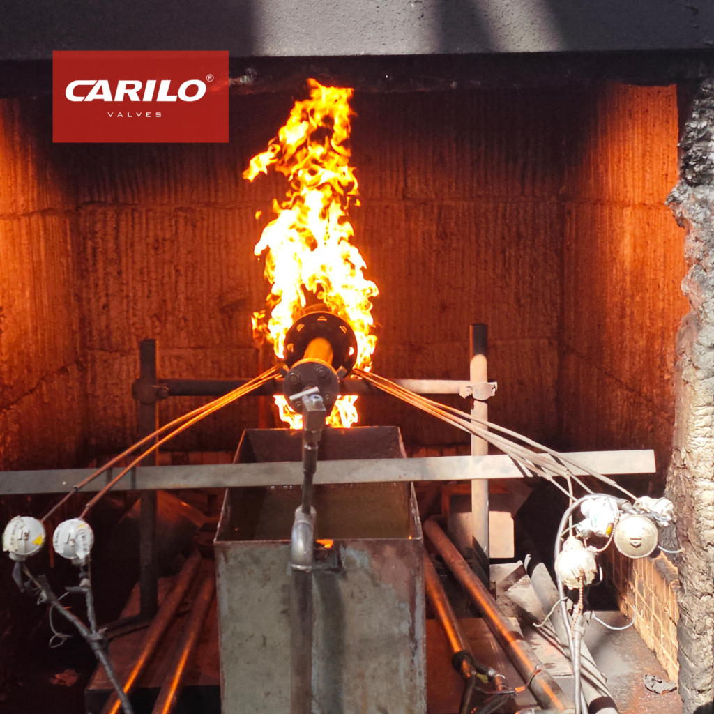
The manufacturer conducts a fire test on API 6D ball valves according to API 607, pressurizing the valve to 75% of the rated pressure, burning it in a 750–1000°C flame for 30 minutes, during which the leakage is continuously monitored not to exceed the specified value, and after cooling, seal and operating torque tests are performed to verify the fire resistance and structural integrity of the valve seat and packing. manufacturer testing System Construction & Pre-pressure API 6D ball valve fire resistance test stands are usually built using 38mm wall thickness seamless steel pipes. The length of the upstream pipeline must reach more than 6 times the valve diameter to eliminate turbulence before the fluid enters the valve body, ensuring that the static pressure value presents a smooth straight line on the transmitter recorder. Technicians use 8 sets of bolts to connect the test ball valve with the flange, and the torque is executed with reference to the ASME B18.2.1 standard to prevent insufficient bolt pre-tightening force during thermal expansion, which leads to premature failure of the sealing surface. After the pipeline structure is fixed, the layout of precision monitoring instruments determines the credibility of the data: K-type thermocouple: diameter 1.5mm, installed at a position 25.4mm away from the valve body surface. Temperature measurement block: material is 1020 carbon steel, size processed to 38mm square, with a hole drilled in the center to embed the probe. Level gauge: accuracy reaches 0.1ml, installed at the end of the downstream condensation pipe to collect trace internal leakage in real time. Pressure transmitter: range covers 0 to 42MPa, sampling frequency set to 10 times per second. Fire barrier: uses fire-resistant board with a thickness of 12.7mm to protect the actuator and non-test parts from high-temperature radiation. Deionized water is selected for the test, and the water temperature is controlled between 5 degrees Celsius to 50 degrees Celsius. An air-driven booster pump pushes the water pressure to the 1.5MPa static pressure required for Class 150 valves, while for Class 300 A105 material valves, the starting pressure must be maintained at 3.8MPa. The system piping reserves about a 5% air pocket as a buffer to prevent pipeline vibration caused by the water hammer effect during violent temperature rise. Two sets of temperature measurement blocks are distributed on the side of the valve body, respectively monitoring the absorbed heat of the middle cavity and the valve cover. The bottom gas pipeline grid is distributed with more than 24 high-performance nozzles, and the mixing ratio of gas and air is controlled at 1:10 by a proportional valve. The propane supply pressure is adjusted to 0.2MPa, which allows the flame to pull the local ambient temperature up to above 700 degrees Celsius within 120 seconds after ignition. The heat application process requires a rigorous laboratory environment as support: Ambient wind speed: The laboratory remains closed, and the anemometer reading must be lower than 2m/s. Flame distance: The vertical distance between the nozzle outlet and the bottom of the valve is locked at 150mm. Downstream volume: The condensation tank volume is not less than 50L, with one-third of crushed ice pre-installed inside. Sealing grease: The valve seat must be thoroughly cleaned with solvent before the test, and it is strictly forbidden to remain any grease that has an auxiliary sealing effect. Installation posture: The valve stem must be installed horizontally to simulate the influence of lateral gravity on the ball valve seal pair in actual working conditions. During the 5-minute observation period, the fluctuation of the pressure transmitter must not exceed 0.05MPa. Technical personnel fine-tune the pressure pointer to the 75% scale mark of the rated value through a manual pump. At this time, the valve is in a fully closed state, the downstream discharge valve is opened, and after confirming that there is no initial internal leakage, the data acquisition system starts the automatic recording mode. The ball is pushed toward the outlet side valve seat under the thrust of 3.8MPa, and the PTFE sealing ring produces a compression deformation of about 0.2mm. This microscopic displacement simulates the stress state of the valve in the early stage of a fire; once the flame contacts the valve body, these polymer parts will undergo a transformation from solid to viscous state and then to carbonization. The condenser adopts a spiral copper tube structure, immersed in a circulating cooling water tank, which can quickly cool steam above 200 degrees Celsius to below 30 degrees Celsius. This temperature difference treatment ensures that every drop of water flowing into the measuring cup is a manifestation of the real internal leakage amount, excluding the interference of gas expansion on volume measurement. Measurement accuracy is guaranteed by the underlying electrical and mechanical parameters: Medium resistivity: must be greater than 1 megohm·cm. Bolt elongation: use an ultrasonic length measuring instrument to record the initial value, with an accuracy of 0.001mm. Variable frequency pump speed: locked at 1450rpm to provide stable back pressure. Shielded cable: adopts Teflon braided mesh to prevent ignition pulses from interfering with sensor signals. A high-voltage discharge spark ignites all nozzles within 0.5 seconds, and the screen temperature curve begins to rise at a slope of 50 degrees Celsius per minute. At this time, the water inside the valve body expands due to heat, and the system overflow valve automatically opens, discharging excess pressure to the return tank, so that the valve cavity pressure is always locked within the range of plus or minus 0.1MPa of the set value. The millivolt signal of the thermocouple and the gram change of the weighing sensor are transmitted to the server through optical fiber. Under this high-frequency monitoring, any minor design defects will be exposed. For example, if the thickness of the seat lip is less than 0.5mm, it will lead to premature deformation of the metal seal pair, resulting in exceeding the internal leakage standard within the first 10 minutes of the test. 760°C – 980°C High Temperature Burning The control room presses the
What Documents Are Needed for API 607 Fire Testing of API 6D Ball Valves | Required Documentation and Certification Requirements
For API 6D ball valves to undergo API 607 fire resistance testing, design drawings, material certificates (EN10204 3.1), pressure rating and dimensional data, test procedures, instrument calibration certificates and type test reports must be provided. The test is usually conducted under a 650°C flame for 30 minutes, and leakage rate and sealing performance are recorded, and certification documents are issued. required documents GA & BOM In GA drawing’s design detail drawings, fire-safe lip and ball surface’s initial gap usually is set between 0.15mm to 0.25mm. When 327 degrees Celsius’s high temperature leads to PTFE soft valve seat melting away, this metal lip will become the only sealing barrier, preventing medium large-scale flowing towards valve downstream. Laboratory through GA drawing checks middle flange’s bolt quantity, Class 300 valve usually configures 8 sets ASTM A193 B7 double-ended studs. Drawing must indicate these bolts’ installation pre-tightening torque, for example 45Nm, to ensure in 30 minutes fire-receiving process valve body connection place will not because of thermal expansion and cold contraction produce exceeding 100ml/min/DN’s external leakage. Bill of Materials (BOM) is GA drawing’s material attribute extension, it stipulates every single part’s ASTM material standard and heat treatment state. BOM inside’s item number (Item No.) needs with drawing bubble index one-to-one correspond, ensuring material’s traceability reaches EN 10204 3.1 level’s audit requirement. Valve body material: ASTM A216 WCB, carbon equivalent (CE) needs to be controlled below 0.43%. Ball treatment: surface needs to electroplate 0.075mm thickness’s hard chrome or ENP, hardness requirement is between 500HV to 800HV. Valve seat spring: selects Inconel X-750 nickel-based alloy, single piece spring’s pre-tightening force usually is set as 1200N. Packing specification: adopts purity higher than 98%’s flexible graphite, chloride ion content must be lower than 50ppm to prevent intergranular corrosion. BOM table inside needs to list non-metallic parts’ supplier brand, for example using DuPont’s Teflon as main valve seat. API 607 stipulates, if actual production in replaced different chemical formula’s sealing material, even if physical size is same, original fire-resistant certificate will also because of material change lose effectiveness. Targeting valve stem place’s dynamic sealing, GA drawing needs to mark packing box’s compression ratio, graphite packing at installation time’s initial compression amount needs to maintain between 25% to 30%. If compression amount is lower than 20%, valve in 980 degrees Celsius’s flame will because of graphite volume shrinkage produce serious valve stem spray-leakage, leading to test directly being declared failure. Valve seat component’s BOM description inside, must contain fire-resistant standby sealing ring’s specification, for example at PTFE ring backward position adding one graphite ring. This graphite ring’s density should maintain at 1.4g/cm³ around, after soft sealing burns away, it can fill valve seat ring and valve body hole between’s 0.1mm coordination gap, cutting off bypass path. Thread specification: valve stem drive end usually adopts ANSI B1.1 standard’s 5/8-11 UNC thread. Surface roughness: metal valve seat and ball’s contact surface roughness needs to reach Ra 0.4 micrometers. Gasket selection: selects with 316SS reinforcement ring’s graphite spiral wound gasket, initial compression stress needs to reach 70MPa. In reviewing Class 600 and above’s high pressure ball valve time, BOM needs to increase towards thrust gasket’s description, usually selects reinforced PEEK or carbon fiber filled PTFE. These parts at high temperature under carbonizing after’s residual thickness needs to be recorded in file, used for calculating valve stem at 3MPa internal pressure under produced’s axial displacement amount. GA drawing inside must embody blow-out proof stem’s geometric step, this step’s diameter must than packing gland’s internal diameter be larger 2mm above. This kind of design ensures even if at packing completely burning away’s situation, valve stem will also not at internal pressure action under fly out, thereby avoiding causing site personnel’s secondary injury. In order to guarantee data’s density and authenticity, BOM also will mark sealing pair’s surfacing layer thickness, if it is STL Stellite hard alloy, its thickness usually is not lower than 1.5mm. This layer high hardness alloy in 1000 degrees Celsius’s flame will not happen softening deformation, guaranteeing 30 minutes fire-receiving period within’s internal leakage amount lower than 400ml/in/min. Material certificate: all pressure-bearing parts must match carry have melting furnace number’s MTR report. O-ring brand: needs to indicate as fluorine rubber (Viton) or perfluoroelastomer (FFKM), temperature resistance needs to reach 200 degrees Celsius. Fastener grade: nut must comply with ASTM A194 2H standard, hardness is in 24 to 35HRC. Certification body before issuing certificate, will compare GA drawing on’s valve seat compression stroke, usually floating ball valve’s valve seat total displacement amount is at 0.5mm around. This displacement amount must be able to compensate ball at 900 degrees Celsius time’s thermal expansion volume, preventing ball and metal valve seat between producing mechanical stuck leading to valve unable at after fire to proceed opening-closing operation. Material Certification Laboratory at before ignition checking’s first piece paper document is pressure-bearing parts’ EN 10204 3.1 material certificate. Auditor holds document to check valve body casting surface knocked’s furnace number steel stamp. Certificate on’s furnace number marks as HT8892, valve body steel stamp knocked into HT8893, this piece valve will be on the spot cleared out of test area. Material certification on’s chemical composition table reveals metal at 980 degrees Celsius high temperature under’s anti-deformation ability. Flipping through conventional carbon steel valve body ASTM A216 WCB’s chemical analysis sheet, carbon content must be stuck below 0.25%, manganese content needs to fall in 0.70% to 1.00%’s interval. After finishing watching chemical composition table, tensile testing machine’s hit out’s mechanical performance data ranks at audit second place. A216 WCB material sheet on’s yield strength bottom line is drawn at 250 MPa, tensile strength stays between 485 MPa to 620 MPa. Elongation after fracture this piece data falls below 22%, indicates material is biased towards brittle, enduring 30 minutes fierce fire baking and sudden cold water pouring strike extremely easily happens fracture. Toughness index through Charpy V-notch impact test data to embody. Applied in minus 29 degrees Celsius environment in’s carbon steel ball valve, material sheet inside has one column
How to Pass API 607 Fire Testing with an API 6D Ball Valve Design | Fire-Safe Design Optimization and Leakage Control
Adopt metal + soft seal dual structure, after fire burn metal seal leakage ≤ 100 ml/min;Packing select graphite withstand temperature ≥ 700℃;Valve seat add spring compensation structure, ensure after thermal deformation still fit;Conduct API 607 full process fire test and cold state re-test verification. design optimization Dual Sealing Mechanism When inside pipe pressure reaches 10 MPa (about 1450 psi) time, PTFE soft ring will be compressed flat 0.15 mm. It tightly sticks on polished to 0.1 micrometer roughness metal ball, one drop of water also cannot leak out. Encounter big fire, valve surrounding temperature will in 3 minutes jump up above 750 degrees. Plastic soft ring at 343 degrees time then starts melting, originally that 0.15 mm deformation instantly vanishes into nothing. Soft ring once burned completely, inside valve exposes a 1.2 mm wide big gap. Inside pipe water is at every minute several hundred liters speed surging outwards. Exactly hiding behind soft ring metal parts, must in a few milliseconds time take over block water task. Engineers at metal seat’s back installed multiple sets of superalloy springs. Ordinary steel springs reach 400 degrees then soften, will lose 90% above elastic force. Change to use Inconel 718 superalloy material, in 1000 degrees big fire inside still can withstand 600 MPa pressure. Under high temperature state, single coil alloy spring every centimeter can push out 50 to 150 Newtons force. Inside pipe water flow back pressure superimposes spring’s push force, takes dozens of kilograms heavy stainless steel seat, fiercely smashes towards equally is stainless steel material’s round ball surface. Contact surface is in advance processed into 3 mm wide chamfer, and on stainless steel surface sprayed a layer of tungsten carbide to prevent wear. This layer coating’s process data is extremely strict: Powder impacts metal surface’s speed exceeds per second 800 meters Coating’s thickness is strictly stuck between 0.15 to 0.20 mm After spraying surface’s Rockwell hardness exceeds 70 Two pieces hardness exceeds 70 metals, under 10 MPa pressure hard hits hard tightly bite. Even if metal surface under microscope exists unevenness, huge squeezing force also takes water flow’s exit path sealed dead. According to standard, 10 inches thick valve burns half an hour, leak water amount must be controlled within per minute 4000 milliliters. Converted down every inch diameter leak water cannot exceed 400 milliliters. Fire stopped, fire-fighting water once poured, 1000 degrees valve body in 10 minutes suddenly drops to 100 degrees below. Metal after cooling violently shrinks, fitted together metal parts will follow to misalign. Been fire roasted springs must in a few minutes inside, precisely catch up 0.01 mm gap change. Real testing time towards this stage’s data tolerance is extremely low: 2 inches small valve in cooling stage leak water lower than 800 milliliters Spring at this time’s deformation compensation amount reaches 0.5 mm Pipeline water pressure from high pressure drops down to only left 2 bar (about 30 psi) Water pressure drops to 2 bar time, water flow cannot push heavy seat, entirely relies on spring’s mechanical force to hard push. Engineers at seat surrounding dug having 5 to 15 degrees tilt angle sliding groove. Under high temperature, between metals friction coefficient will from normal temperature’s 0.15 wildly surge to 0.6 above. Inside sliding groove in advance applied a layer 20 to 30 micrometers thick molybdenum disulfide dry film. It under 1200 degrees same as usual plays lubrication role, guarantees spring pushing seat time stuckness does not exceed 0.1 seconds. To achieve no stuckness at all, internal parts processing time’s size tolerance approaches machining’s limit: Internal round ball’s tolerance cannot exceed 0.015 mm Spring installation height’s error requires smaller than 0.1 mm Tilt sliding groove surface’s roughness requires to reach 0.4 micrometers Metal ring is designed to become compared to plastic ring move backwards 0.1 mm, usually completely not receive wear. Fire destroys plastic after, this 0.1 mm gap exactly is by spring filled. Managing Thermal Expansion Usually easy to use metal parts, thrown into 750 degrees above sea of fire inside will thoroughly change shape. Take a piece 500 mm long 316 stainless steel valve stem to say, temperature burns to 1000 degrees time, it will out of thin air grow longer about 8 mm. Inside pipe solid metal ball expands even more exaggeratedly. A 10 inches thick full bore ball valve, inside that diameter about 250 mm stainless steel ball receives heat after, outer ring will fully bigger out nearly 4 mm. Originally factory inside only left 0.15 mm movement gap, basically cannot stuff down expanded iron ball. Become bigger metal ball just like hydraulic press same, towards two sides tightly pushes against seat, forcibly squeezes out hundreds of tons push force. If take a few micrometers gap calculated wrong, worker in fire scene inside even if put on a 1.5 meters long force-adding iron stick, use up 4500 Newton-meters strength to turn, also do not think to take valve rotate half a fraction. Ordinary A105 carbon steel’s thermal expansion coefficient is about 12×10 negative 6 power/℃, inside anti-corrosion used austenitic stainless steel can run to 16.5×10 negative 6 power/℃. Metal Material Expansion Coefficient (10 negative 6 power/℃) 1000 degrees under 100 mm expansion amount Receive heat after actual performance A105 carbon steel 12.0 1.15 mm Surface severely peels off drops slag 316 stainless steel 16.5 1.60 mm Shape twists changes shape F51 duplex steel 13.5 1.30 mm Under high temperature easy to become brittle crack open Inconel 718 13.0 1.25 mm Still maintains extremely high hardness Outside wrapped carbon steel grows slow, inside stainless steel ball grows fast, internal parts forcibly are squeezed into a getting smaller and smaller iron box inside. A piece diameter 50 mm valve stem by fire once roasted, thickens 0.8 mm. Drawing at stem and hole wall middle drew out having steps gap. In order to prevent leak water, bottom’s gap always stuck at 0.1 mm, top’s gap is intentionally widened to 0.35 mm. Fire just burns up’s first 10 minutes, stem upper end will rapidly
What Inspection Items Matter Most When Buying an Industrial Ball Valve | pressure testing, surface finish, dimensional accuracy
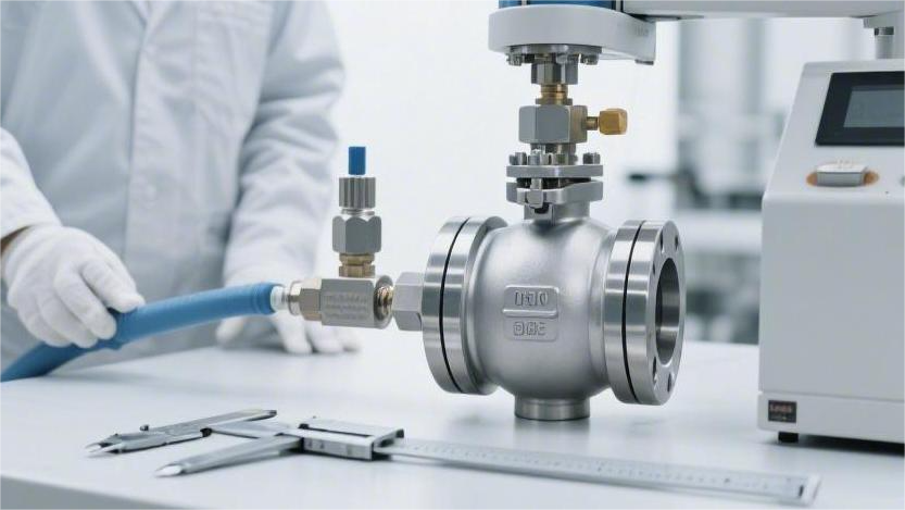
When purchasing industrial ball valves, focus on verifying that the hydrostatic test reaches 1.5 times the design pressure, the pneumatic sealing test shows zero leakage, the sealing surface finish is controlled to ≤ Ra 0.8 μm, and critical dimensional tolerances are held within ±0.05 mm. The opening and closing torque and concentricity should also be rechecked under the API 598 inspection procedure to ensure stable installation. Pressure Testing Shell Strength Test If the metal contains shrinkage cavities or inclusions above Grade 2, those weak spots can rupture and leak as soon as the body is subjected to hydrostatic pressure at 1.5 times normal working pressure. During the test, the ball valve must be kept in a half-open position. Workers use heavy-duty blind flanges to seal both ends of the valve completely. Bolt tightening is also strictly specified. For example, when testing an 8-inch Class 300 carbon steel ball valve, alloy steel bolts are required, and a torque wrench is typically set between 600 and 800 N·m. Water is then filled into the valve cavity, and all trapped air must be fully vented. An air-release valve is installed at the highest point of the body, and clean water is introduced at a flow speed of 0.5 m/s. Only when the discharge at the vent stops producing bubbles is the valve considered completely filled. Even a small amount of trapped air can cause the pressure gauge needle to fluctuate and distort the test reading. The test water temperature cannot be too low or too high and is generally controlled between 5°C and 50°C. Below 5°C, steel becomes brittle. For stainless steel valves, purified water must be used, with chloride ion content kept below 50 ppm to prevent corrosion. Blind plugs / blind flanges: must meet the standard minimum thickness requirement Sealing O-rings: high-pressure fluororubber capable of withstanding 42 MPa maximum hydrostatic pressure Test water quality: high purity, with conductivity controlled within 20 μS/cm Low-temperature steel: must be conditioned at room temperature for 4 hours before pressure testing Once the pump starts, the pressure gauge needle begins to rise, but the pressurization rate cannot be too fast. It must not exceed 1.5 MPa per second. For a Class 600 ball valve rated for 10.0 MPa, the test pressure must be driven up to 15.0 MPa, and the entire pressurization process must last at least 10 seconds. If the pressure rises too abruptly, the bolts securing the bonnet can deform under the load. Only after the needle has stabilized completely at 15.0 MPa can the worker start timing the pressure hold period. The larger the valve size, the longer the observation period required. Below 2 inches: hold and observe for 15 seconds 2.5 to 6 inches: hold and observe for 60 seconds 8 to 12 inches: hold and observe for 120 seconds 14 inches and above: hold and observe for 300 seconds During this period, the inspector uses a high-intensity flashlight and a long-handled inspection mirror to examine the valve body from all angles. Any visible seepage, misting, or even the slightest “sweating” on the shell is enough to fail the valve. On sand-cast valves, special attention is paid to joints and riser areas, where wall thickness can sometimes be 12.5% thinner. There is also packing around the stem to prevent leakage. If it is not compressed properly, problems appear immediately. On high-pressure valves such as Class 900, hydrostatic testing at 22.5 MPa generates several tons of outward force. Even 1 mm of packing deformation can cause water droplets to emerge from the gland area. On large forged steel ball valves with 24-inch openings, the body cavity can hold several cubic meters of water, and filling plus pressurization alone can take most of a day. The pressure gauge is mounted at the highest point of the blind flange. Its dial must be at least 100 mm in diameter, and its accuracy class must meet Class 1.6. Pressure gauges cannot be chosen casually. The full-scale range must be between 1.5 and 4 times the test pressure. For a 15.0 MPa hydrostatic test, a 25.0 MPa gauge is appropriate, placing the needle in the most accurate central zone of the dial. Bonnet gasket edge: watch closely for hanging water droplets Shell corners and edges: apply white chalk dust; even slight dampness leaves a dark stain Packing gland: watch whether water slowly creeps upward in the gap Drain plug: check whether the threaded joint feels completely dry Grease injection valve: verify whether the check ball leaks under water pressure When the hold period ends, the worker slowly opens the relief valve and lets the high-pressure water drop at a controlled rate of 2.0 MPa per second. Natural draining is not enough, because water remains trapped in dead corners. A 0.6 MPa compressed air line is then connected to blow through the valve cavity for 3 to 5 minutes. Sealing Test Once the high-pressure hydrostatic shell test is complete, the sealing test begins immediately. The pump raises the pressure on one side of the valve cavity to 1.1 times the normal working pressure. For a Class 600 carbon steel ball valve rated at 10.0 MPa under ambient conditions, the test pressure is raised to 11.0 MPa. Under API 598, a 4-inch metal-seated ball valve is allowed to leak no more than 8 drops of water per minute. A sheet of white paper or a graduated glass beaker is placed underneath to collect leakage, and 1 mL of water is approximately equal to 16 drops. For soft-seated ball valves using PTFE, the requirement is much stricter. Under ISO 5208 Rate A, not a single drop of water is allowed to pass. The inspector shines a flashlight along the dry metal outlet for a full 2 minutes. If even the slightest trace of moisture is seen in the reflection, the valve must be disassembled and reworked. The hydrostatic sealing test is not the end of the process. A workshop compressor then feeds about 0.6 MPa of dry nitrogen into
What Causes Industrial Ball Valve Failure in Harsh Working Conditions | seal wear, pressure fluctuation, material mismatch
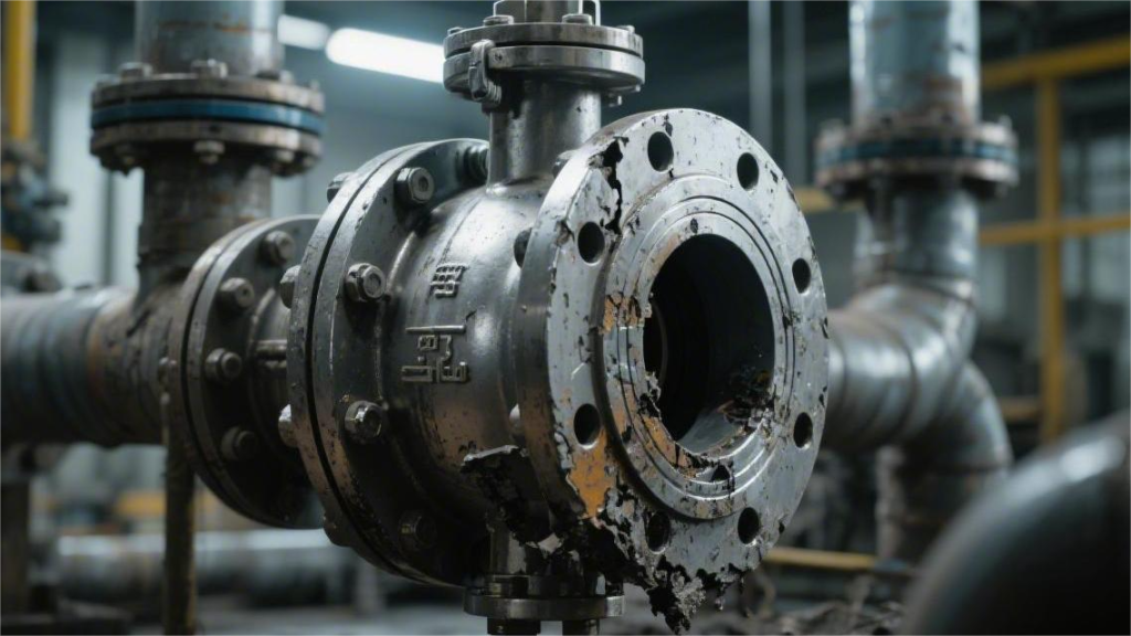
Industrial ball valves in severe service most often fail because seal wear exceeds 0.2 mm/year, pressure fluctuations go beyond ±20% of the design value, or materials are mismatched. In H₂S-containing service, for example, failing to use duplex stainless steel can sharply accelerate corrosion. During operation, torque variation should be monitored regularly; if it rises by 15% or more, the valve should undergo seal retesting in accordance with API 598 to prevent failure. Seal Wear Solid Particles In a 50 mm industrial pipeline, crude oil rushes through at 8.5 m/s. The fluid carries entrained particles, including quartz sand and rust flakes ranging from 15 microns to 2 mm. As the crude approaches a half-open ball valve, the flow area drops sharply from 1,960 mm² to less than 400 mm². The narrowed passage drives the flow velocity up to four times its original speed. The suspended quartz sand gains enormous kinetic energy. With a Mohs hardness of 7, these grains behave like miniature armor-piercing projectiles when they strike a soft plastic surface with a hardness of only Shore D55. Microscopic observation captures the force of impact. A single 0.5 mm sand particle, driven by a 3.2 MPa differential pressure, can instantly tear a groove 0.08 mm deep into an otherwise smooth surface. Common destructive particles found in pipelines include: Sharp quartz sand (hardness 7) Highly abrasive alumina powder (hardness 9) Large rust scale flakes (hardness 5 to 6) Crystalline salts prone to clogging (hardness 4) When fluid carrying hard solids flows through the valve, foreign matter is forcibly wedged between the ball and the seat. A gap of just 0.1 mm can result in a leakage rate of 45 liters per hour under a 2.0 MPa water pressure condition. The escaping fluid acts like a wire-cutting jet. Following the initial scratch, the high-speed stream erodes deeper along the damaged path, and a tiny 0.08 mm pit can expand into a 2.5 mm-wide deep groove within 48 hours. During valve actuation, particles attached to the ball surface are dragged into the sealing interface. As the ball rotates 90 degrees under a torque of 150 N·m, those particles cut into the surface like lathe tools. A natural gas master valve that had been in service for 120 days was dismantled for inspection. Its soft seat ring, originally 6.35 mm thick, had been abraded by sand and gravel until the thinnest section measured only 1.2 mm, with dense scratches deeper than 0.5 mm across the surface. These scratches destroy the protective barrier. Fine powder packs into the grooves and becomes compacted under pressure. As a result, the coefficient of friction rises dramatically from 0.04 at the factory to above 0.3. As friction multiplies, the air pressure required by the pneumatic actuator climbs from 0.4 MPa to 0.65 MPa. If the air supply becomes insufficient, the ball can stall in a half-open position at 45 degrees. A stalled ball then faces severe erosion. The fluid forms a jet at over 40 m/s, and the entrained metal fragments can pit a 316 stainless steel ball surface densely within just 3 minutes. Laboratory testing has quantified particle-related loss. In a slurry with a solids content of 3%, after 5,000 continuous operating cycles, conventional nylon components showed a mass loss rate of 18.5%. Service life under abrasive conditions varies significantly by material: Standard soft plastic parts: surface roughness fails after 24 hours Carbon-fiber-reinforced parts: grooves appear after 150 hours PEEK hard plastic: deformation reaches 5% after 300 hours Surface-hardened metal parts: maintain zero leakage for 1,200 hours A refinery catalytic cracking unit switched to a metal seat housing coated with tungsten carbide. The coating thickness was controlled at 0.2 to 0.3 mm, with a hardness of HV 1100. Under particle impact at the same flow velocity, the hardened surface showed only 0.005 mm micro-scratches. The high-speed sand particles rebounded on impact and were deflected toward the inner flow channel wall. Ultrasonic thickness inspections showed that in a water injection pipeline with a sand content of 5‰, a 12 mm carbon steel elbow wore down to the retirement threshold of 8.4 mm within 18 months. Installing a Y-strainer 1.5 meters upstream helps reduce the impact. A 40-mesh stainless steel screen with an aperture of about 0.4 mm can intercept large, hard particles. Increasing pipe diameter also reduces fluid velocity while maintaining the same flow rate of 200 m³/h. Expanding the diameter from 80 mm to 100 mm lowers the medium velocity from 11 m/s to 7 m/s. Lower velocity reduces kinetic energy on a square-law basis. When the speed falls to 63% of the original value, particle impact energy drops to 40%, and the wear rate decreases significantly. Equipment adjustments that help reduce fluid damage include: Installing a desander upstream to remove particles above 50 microns Increasing pipeline cross-sectional area to reduce initial fluid velocity Adjusting the pump inverter to lower supply pressure by 0.5 MPa Switching to a full-port design to minimize internal turbulence Even with filtration, micron-scale fine dust inevitably remains in the pipeline. These tiny crystals behave like polishing compound, settling silently along the contact line between the ball and the seat. With every rotation, a 0.01 mm layer of fine particles is compressed into the polymer structure. After six months of penetration, a white material can turn dark gray and become as brittle as cast iron. When such an embrittled component contracts under nighttime temperatures of -15°C, the internal stress can exceed its 15 MPa tensile limit. With an audible crack, a through-fracture as long as 40 mm can form. High-pressure gas at 6.0 MPa then escapes through a 0.2 mm crack. The violent vortex formed in the rear cavity can literally tear the entire seat assembly out of its retaining groove. Dry Friction & Torque Variation Pure high-pressure nitrogen flows continuously through a 4.0 MPa pipeline network. The automated control program requires the valve to open and close 800 times per day. Because the gas contains no moisture or oil at all, the polished
How Buyers Shortlist Ball Valve Manufacturers for New Projects | project fit, sample quality, certification readiness

When evaluating ball valve manufacturers, buyers first match the supplier’s offering to the project requirements, such as Class 300–1500 pressure ratings and service temperatures from -29°C to 425°C. They then assess sample performance against criteria including leakage within API 598 limits and opening/closing torque deviation within ±10%, while also confirming API 6D certification, ISO 9001 certification, and complete material traceability reports. In most cases, buyers compare 3–5 suppliers before selecting a qualified manufacturer. Project Fit Materials & Service Conditions Buyers start by reviewing the factory’s procurement records from the previous year, checking mill delivery notes line by line. What they are looking for is 2507 super duplex stainless steel. Its corrosion resistance rating, expressed as PREN, must exceed 40. Even a shortfall of 0.1 is enough for the entire heat of molten steel to be rejected and sent back to the mill. An inspector presses a handheld spectrometer firmly against a cut metal sample for 30 seconds. The display immediately shows the percentages of chromium, molybdenum, and nitrogen. A 24-inch valve body is then scanned with an ultrasonic flaw detector. If the image reveals even a 2 mm crack, the entire casting is rejected. Ferrite content must stay strictly between 35% and 55% Annealing temperature must be held at exactly 1040°C At -46°C, impact energy must still reach 45 J Weight loss in ferric chloride solution must not exceed 4 g At sour gas sites, field pipelines can contain hydrogen sulfide concentrations as high as 150,000 ppm. Ordinary steel can blister and crack apart within hours under those conditions. For this type of service, the specified material is often upgraded to costly C276 alloy. Where budgets are tighter, a layer of Inconel 625 is overlaid onto standard steel. The valve cavity is coated evenly with an acid-resistant protective layer at least 3 mm thick. A welder qualified to ASME Section IX works in full protective gear. Using GTAW, the welder slowly deposits the weld on the inner wall of the shell, which has been preheated to 150°C. A supervisor then checks the finished surface point by point with a calibrated gauge. The drawing requires a probe reading every 10 mm. If the instrument shows iron contamination above 5%, the entire area is ground out and welded again. Surface hardness must not exceed 22 HRC The surface is checked under a microscope for fine cracks Cooling curves are monitored after welding in a heat-retention enclosure Dye penetrant is used to check whether edge areas show bleed-out In coal preparation plants, the pipeline carries thick black slurry containing 30% hard coal ash, with operating temperatures reaching 450°C. A white PTFE seat exposed to that hot slurry can soften within seconds. In those workshops, all soft components are replaced with cast iron and hardened steel. Next to the machining table, a robotic arm turns and directs its spray gun at a polished steel ball. Fine tungsten carbide powder is driven forward by combustion gases. The powder strikes the steel surface at roughly Mach 2.5, forming an ultra-hard “armor” layer 0.3 mm thick. The coated parts are then moved into a furnace at 980°C and fired repeatedly until the coating becomes a fully bonded hard shell. After firing, two skilled technicians spend four full hours hand-lapping the ball and seat with 400-mesh diamond compound. The assembled unit is bolted together and connected to a thick hose charged with high-pressure nitrogen. An infrared camera watches continuously for leaks. If leakage stays below 0.0005 mL over one minute, the unit passes, and a V-grade leak-tightness label is printed immediately. Surface hardness exceeds 68 HRC Bond strength is greater than 70 MPa Ball surface finish is polished to 0.1 μm Sphericity tolerance is kept within 0.02 mm LNG tanks operate continuously at -196°C. Buyers therefore review how the 316L stainless components were treated for cryogenic service. Hundreds of metal pieces are loaded into stainless steel mesh baskets and immersed in liquid nitrogen for a full 24 hours. This extreme thermal cycling forces the internal structure into a more stable state, keeping shrinkage deformation below 0.15% once installed in cryogenic piping. Soft graphite packing is not permitted at the stem position. Instead, assemblers install a special PCTFE ring with a custom hex tool. Inside that ring is a U-shaped corrosion-resistant metal spring. No matter how low the outside temperature falls, the spring keeps constant pressure on the plastic ring to prevent leakage. A helium leak detector is then brought in. The inspector moves the suction probe slowly around the stem seal area. The scanning speed is kept at 10 mm per second. On the display, the leakage reading remains safely below the 100 ppm limit. Capacity & Lead Time For a 400 km gas transmission line, the requirement may be clear: 8,000 ball valves of various sizes must be delivered within six months. Buyers do not rely on sales claims alone. They count the machines themselves. On one side of the workshop are 45 CNC lathes with digital displays; on the other are 12 horizontal machining centers. They watch the cycle timers on the screens and use stopwatches to verify machining time per unit. For a standard 8-inch carbon steel body, the cutting tool may need 35 passes across the workpiece. Just keeping the spindle running for that job can consume 45 minutes. Some factories claim “10,000 units per month” in glossy brochures, but buyers want proof from the shop floor. Experienced buyers will go as far as checking three months of employee attendance records and comparing them against electricity bills from the utility provider. Two shifts rotate between day and night work Machines run 16 hours per day at full capacity Workers operate 6 days per week The plant stops for 3 maintenance days every month With those figures, a buyer can quickly calculate the factory’s true monthly output ceiling. Large-diameter valves slow everything down dramatically. At one crude oil terminal project, the urgent requirement was for several 48-inch pipeline ball valves. Each finished valve weighed
