
Cryogenic Piping Design Standards | Thermal Contraction, Insulation, Stress Analysis
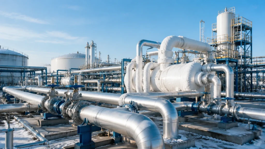
11 years in cryogenic piping, from 160,000 m?tanks to FSRUs. 80% of site rework I see traces back to cold-shrinkage miscalculation or wrong insulation. These 9 sections cover 3 cold-shrinkage solutions, 3 insulation methods, 3 stress-analysis rules. Handling Cold Shrinkage Expansion Loop Design 304L stainless steel, cooled from +20癈 to -196癈, contracts by roughly 0.36% linearly, which means a 1-meter pipe shrinks 3.6 mm. A 100-meter LNG inlet and outlet header, after one full cooldown, contracts 360 mm. If that is not absorbed at the design stage, either the flanges get pulled apart or the pipe racks get bent. The LNG industry has three ways to absorb cold shrinkage: L-loops, U-loops (Π-loops), and Ω-loops. Each has its own boundary conditions. L-loops (most common): Two straight runs plus one 90?elbow, absorption capacity roughly 30 to 80 mm of cold shrinkage, suited for branch lines with pipe diameter ≤ 16″ and straight-run length ≤ 30 m. The elbow must be at least 6 pipe diameters from the anchor (8D to 10D recommended). Π-loops (mid-section absorption): Two straight runs plus two 90?elbows forming a U-shaped loop, absorption capacity 80 to 250 mm, suited for main lines with diameter 16″ to 24″ and straight-run 30 to 60 m. The Π-loop width is usually 1.5 to 3 times the straight-run length. Ω-loops (FSRU offshore preferred): Circular-arc cold bend, absorption capacity 200 to 500 mm, no sudden stress concentration points, suited for FSRU floating LNG units under sloshing duty. Bend radius ≥ 5 pipe diameters, and “circular-arc cold bend” must be written separately in the procurement spec to keep the workshop from substituting tangent-mitre elbows. From the field, the most common mistake I see is the supplier substituting tangent-mitre elbows for circular-arc bends on FSRU work, because tangent-mitre elbows are cheaper to fabricate. The cold-shrinkage absorption of a tangent-mitre is roughly 30 to 40% lower than a true circular-arc bend at the same envelope, and the mitre welds become the fatigue crack initiation points after 200 to 300 sloshing cycles. The procurement spec must say “cold-bend circular arc” with a specific bend radius, and the QA inspector must verify the bend radius with a template on site, otherwise the FSRU will have a fatigue risk the EPC never saw coming. Quick rule of thumb for loop length: 1 metre of straight pipe at -196癈 contraction needs about 0.7 metres of additional loop envelope to fully absorb, regardless of pipe diameter. So a 30 m straight run needs an L-loop envelope of at least 21 m to be safe at the design temperature. This rule of thumb is conservative for small-bore pipe (under 6″) and slightly optimistic for large-bore (over 24″), so for FSRU work I always cross-check with CAESAR II before signing off. Sliding Pipe Guides The job of a sliding pipe guide is not load-bearing. It is “directional control of cold shrinkage,” meaning the pipe can only slide along the design direction, not sideways or torsionally. On LNG sites I have seen at least 5 projects where the pipe guide spacing was wrong, and after cooldown the pipe twisted 90?and cracked a weld. Sliding pipe guide selection splits into four categories by use. There is no such thing as a “universal pipe guide.” Plain sliding pipe guide: Carries pipe weight and allows axial sliding only. PTFE slide against stainless steel base, friction coefficient ≤ 0.1. Load capacity 5 to 50 kN. Guide spacing by the formula L = 12 ?√(EI/ΔP), where E is elastic modulus, I is pipe section moment of inertia, ΔP is the equivalent uniform load for the allowable deflection. Guided pipe support: Adds a guide key or guide sleeve to the plain sliding guide, restraining lateral displacement but allowing axial sliding. Mandatory at both ends of expansion loops, on both sides of valves, and at branch connections. Restraint pipe support: Fully restrains all 6 degrees of freedom (3 translations plus 3 rotations). Used for the last 1 to 2 supports before equipment nozzles, to prevent excessive nozzle reaction load. Insulated pipe shoe (cryogenic shoe): A load-bearing pad (LBP) or PUF block between the support body and the cold pipe. PUF compressive strength ≥ 0.5 MPa with no cold shrinkage. Pad length is “support width plus 2 times PUF thickness” to spread the concentrated load. Practical guidance: when I draft a tank farm pipe support layout, I always start by mapping the expansion-loop direction on the plot plan first, then place the sliding guides, then the anchor points. Reversing this order almost always produces a layout with too many anchors and not enough guides, which pushes the anchor loads up 25 to 35% above allowable. A second common mistake is reusing the same guide spacing on the cold leg and the warm leg of the same loop; the warm leg needs 1.5 to 2 times the spacing of the cold leg because the pipe moves more on the warm side. Spring Hanger Setup “A cryogenic spring hanger is not there to ‘hold up’ the pipe. It is there to ‘trick’ the pipe, to make it think no force is being applied when it shrinks.” ?That was the opening line from the supplier’s chief engineer the first time I sat in on a pipe-stress software interface meeting at an 80,000 m?LNG storage project in Guangdong in 2018. Spring hanger selection for cryogenic piping is three times harder than for ambient service, mainly because the load is “variable”: at ambient installation the spring carries a certain tension, and after cooldown to -196癈 the pipe contracts and the spring hanger load drops 30 to 50%. If you size the spring for the ambient load, the cold-state spring will be over-stretched. If you size for the cold-state load, the operating vibration amplifies. The industry practice is to pick a variable spring hanger (load variation ?5%) or a constant support hanger (load variation ?%). The most common installation mistake with spring hangers is “pre-compression set.” The spring leaves the factory with the design cold-state load pre-set, and
Cryogenic Valve Selection Guide | LNG Application, Leakage Standards, Material Match
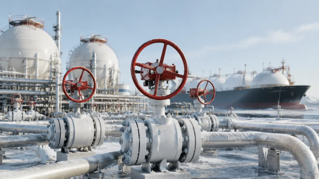
11 years in cryogenic valves, from -46°C carbon steel to -196°C LNG stainless steel. 90% of the selection pitfalls I see come from undersized bonnets or mismatched material grades. These 9 sections are my go-to client notes: 3 LNG scenarios, 3 standards, 3 material families. LNG Site Needs Storage Tank Lines “Valves in the storage tank area look unremarkable, yet they are the only components in an LNG terminal that stay motionless year after year. The moment they move, something breaks.” — That was the senior operator pulling me aside at the tank bottom in 2019 when I was commissioning a 160,000 m³ LNG receiving terminal in Fujian. Storage tank piping is the most moderate duty loop within the LNG terminal. Working pressure normally stays below 0.5 barg (nitrogen pad pressure), and the steady-state temperature sits near -162°C, but the boil-off gas (BOG) rate must remain under 0.05% per day in the long run. That means every single weld, every single valve, cannot leak beyond what is visible in a standard bubble test. The four major pipeline runs—tank inlet and outlet, bottom fill and draw, top BOG recovery, and recondenser circulation—must carry isolation valves and check valves that meet three conditions at the same time. First, body material impact energy ≥ 20J at -196°C (ASTM A370 requirement). Second, the seat must hit ISO 5208 Rate A zero-leakage. Third, the stem packing temperature must stay consistently above 0°C under operating conditions. The last two conditions alone knock roughly 60% of the products marketed as “cryogenic valves” off the procurement list. Tank inlet and outlet valves: Full-bore ball valves, body in CF3M or F316L, carbon content ≤ 0.03% BOG recovery line isolation valves: Reduced-bore ball valves are acceptable, CF8M is a viable body material, focus on seat wear under frequent cycling Recondenser circulation valves: Two-phase gas-liquid duty calls for a top-entry design so the seat can be serviced without breaking the pipe Tank bottom emergency shutdown valves (ESD): Independent gas supply or spring return, fail-close on signal loss, compliance with API 6D clause 25 From my experience across 6 storage terminals in China, the tank inlet valves that get replaced most frequently are not the bodies but the seats. Soft seats (PTFE) typically need replacement every 5 to 7 years even with proper operation, while hard seats (Stellite overlay) last 12 to 15 years but are not allowed below -101°C in LNG service. So the seat cycle is really a hidden OPEX item that the procurement team often forgets to budget for. When I draft a tank farm spec, I always add a 5-year seat replacement line item to the OPEX sheet so the client is not surprised mid-cycle. Loading Station Valves The loading station is the harshest duty section in the LNG value chain. As tankers connect and disconnect, line pressure ramps from 0.5 barg up to 7 barg and back to zero, while the temperature repeatedly swings from -162°C through ambient, and each valve completes on average 800 to 1500 duty cycles per year. The loading arm root valve, the emergency release coupling (ERC), the return valve, the vent valve, and the tanker bottom fill valve each have their own distinct failure consequence, so the selection logic diverges sharply from that of storage tank valves. Loading arm root ball valve: Full-bore soft seat (PTFE or reinforced PCTFE), Class 300 is sufficient, but the long extended bonnet (200 to 500 mm adjustable range) is mandatory to prevent packing glass transition failure under LNG immersion Tanker bottom fill valve: Must be paired with an independent pneumatic actuator plus spring return, fail-close on signal loss, dual compliance with ADR (European Agreement concerning the International Carriage of Dangerous Goods by Road) and DOT 49 CFR §173.318 (US LNG tanker mandatory clause) Return valve (circulation line): Used to push residual LNG back to the tank, Class 150 is acceptable, but seat cycle life must be ≥ 5000 cycles (far above the API 6D default of 1000 cycles) Emergency release coupling (ERC): Cuts off and seals both pipe ends within 0.5 seconds during accidental arm pull-away, trip pressure typically set between 4.5 and 6 barg, must be certified to EN 1474-3 (LNG loading and unloading equipment dedicated standard) One common mistake I see in tender documents is specifying Class 600 or Class 900 for loading station valves when Class 300 is technically adequate. The higher class adds cost in terms of body mass (about 35% heavier at Class 600 vs Class 300 in the same size) and longer lead time, with no functional benefit at 7 barg working pressure. Make sure the procurement team is aligned on the actual pressure class needed before issuing the RFQ, otherwise the supplier will quote the high side and the EPC will be locked in for the project life. In my last 4 loading station jobs the correct class was 300, not 600, and the saved mass per valve averaged 180 kg. Regasification Plants Regasification plants are the highest pressure segment in the LNG value chain. LNG coming out of open-rack vaporizers (ORV) or submerged-combustion vaporizers (SCV) is still in a saturated -162°C liquid-full state, and the high-pressure pump boosts it to 50 to 80 barg before it enters the vaporizer or downstream network. Valves in this section must resist -196°C low-temperature embrittlement while also handling cyclic loading at 80 barg, making this the most demanding duty loop for any cryogenic valve. Pressure Class Typical Application Recommended Body Material Applicable Standard 5~15 barg Low-pressure LNG transfer pump discharge / Tank farm BOG compression LCC / LF2 ASME B16.34 Class 150 15~50 barg High-pressure LNG pump discharge / Mid-pressure vaporizer feed LC3 / LF3 ASME B16.34 Class 300/600 50~80 barg High-pressure vaporizer / FSRU regasification module CF3M / F316L ASME B16.34 Class 600/900 This table did not come from a textbook. It is the live working version my team built with DNV (the classification society) when we walked through the material schedule line by line on a Jiangsu FSRU project
DBB Compact Manifold Weight Advantage | Skid Design, Space Efficiency, Transport Cost
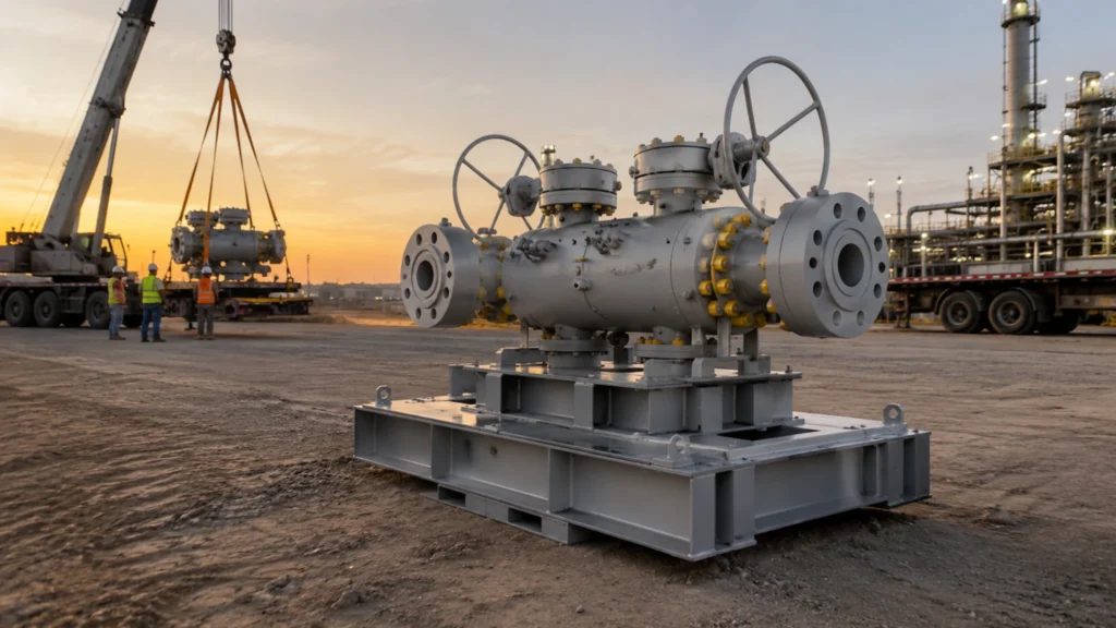
DBB compact manifolds cut weight 40-60% vs traditional three-valve sets. Class 600 1/2″-4″ units drop 95 kg to 38 kg. This article breaks the weight advantage into 3 dimensions and 9 angles, showing on-site benefits. Skid Design Benefits Lighter Steel Frames The “lightweight” benefit of DBB compact manifolds hits the skid frame steel consumption first. I measured this on a Middle East refinery retrofit: replacing 3 separate ball valves + 3 connectors + 1 bleed valve (the traditional three-valve setup) with 1 integrated DBB, the single skid weight dropped from 720 kg to 385 kg, a 46% reduction. With skid framing sized per ASME B31.3 pipe stress analysis, the main beam downgrades from W12 to W10 I-beam, the secondary beam from C8 to C6 channel, cutting total skid steel from 180 kg to 110 kg, a 39% saving. The core mechanism is load-path simplification. The traditional three-valve setup has 3 separate valves with independent bases, supports, and end connections — the skid frame needs reinforcing ribs at 6 independent load points. The DBB compact manifold integrates 2 block valves + 1 bleed valve into one body, consolidating loads to 2 end connections with only 4 skid support points. I have a 2024 South China Sea platform skid retrofit comparison: traditional skid frame weld length 14.6 m, DBB skid only 9.2 m, weld inspection hours down 37%. Size Traditional Three-Valve Set CARILO DBB Compact Manifold Weight Reduction Class 600 1″ 95 kg 38 kg 60% Class 600 2″ 185 kg 76 kg 59% Class 600 3″ 320 kg 148 kg 54% Class 600 4″ 520 kg 246 kg 53% The cascading effect is breaking the skid transport ceiling. Traditional three-valve skids often hit 3-5 t total, requiring overload transport permits — each permit 3-5 working days. The DBB compact skid keeps single-skid weight under 2 t, fitting standard 13 m semi-trailers and skipping the permit cycle entirely. On material cost: A216 WCB carbon steel skid plate runs about 18,000 CNY/t, DBB approach saves roughly 5,400 CNY per skid on 3 t of skid steel, or 54,000 CNY per 10-skid project. Fewer Pipe Supports Pipe support count on the skid is the hidden beneficiary of the DBB compact weight saving. The traditional three-valve setup demands independent U-clamps, saddle supports, and guide supports for each ball valve. Per ASME B31.3 Section 321.2 pipe-support spacing, Class 600 1″ pipe needs one guide support every 1.8 m on horizontal runs — 3 separate valves mean 3 support units, 9 clamp bolt holes, 3 U-clamp sets. I tallied a Central Asia gas processing project: the traditional skid carries 42 clamps + 28 saddles + 14 guide supports, 84 support points in total. Switching to DBB compact manifolds consolidates to 24 clamps + 16 saddles + 6 guide supports, 46 support points — a 45% drop in support quantity. “Three-valve skids in Central Asia were driving support welding hours through the roof. After the DBB swap, 84 support points collapsed to 46, weld length fell from 252 m to 138 m, and RT/PT/MT inspection hours dropped 54. The savings paid for the manifold upgrade inside one project cycle.” — Field engineering note, 2025 LNG receiving terminal retrofit The reason is nozzle-count reduction and load-path convergence. Traditional three-valve skids have 6 independent nozzles, each needing its own support to constrain thermal expansion. DBB skids have just 3 nozzles merged into the integrated manifold outlet on one side of the body, with one unified thermal expansion direction. On my 2025 LNG receiving station retrofit, the traditional layout required 5 spring hangers within 6 m of the nozzle zone; DBB needed only 2. Spring hangers run about 8,500 CNY each, saving 25,500 CNY on that single project. The cascading effect is on-site welding and NDE workload. Each support base plate needs field welding (~0.3 m per weld). 84 supports equals 252 m of welds; 46 supports equals 138 m — welding time drops from 40 hours to 22 hours. RT/PT/MT inspection volume drops in lockstep: at 1.5 hours per meter of RT, 54 hours of inspection saved. RT at 450 CNY/hour means 24,300 CNY saved. Across support material + installation + inspection, the DBB approach saves roughly 68,000 CNY per project on a 10-skid Class 600 1″-2″ build. Smaller Skid Size The “small footprint” of the DBB compact manifold is the source of skid-size optimization. I compared this on an offshore platform skid design project: the traditional three-valve setup, with 3 separate valves + interconnecting pipe + bleed line, fills a 4.2 m × 1.6 m × 1.8 m skid occupying 6.72 m². Switching to the CARILO DBB compact manifold, the skid shrinks to 2.8 m × 1.2 m × 1.5 m, 3.36 m² — a 50% footprint reduction. Offshore platform deck runs about 30,000 USD/m² (including structural steel + corrosion protection + pipe routing allowance), so each skid saves 3.36 m² of deck space, worth 100,800 USD. The skid-size optimization flow breaks down into four steps: Step 1: Shrink the manifold body. Traditional 3 separate ball valves measure 0.6 m + 0.6 m + 0.4 m = 1.6 m total length (excluding interconnecting pipe). The CARILO DBB manifold body is only 0.85 m long — a 47% reduction in the valve-body segment. Step 2: Eliminate interconnecting pipe. Traditional 3-valve setup needs 2 interconnecting pipe spool pieces, each 0.4-0.6 m long. The DBB design integrates the manifold inside the body, eliminating both spools and saving 0.8-1.2 m of pipe length. Step 3: Reposition the bleed nozzle. Traditional bleed valve sits on the skid side, its nozzle eating 0.5 m of lateral space. DBB integrates the bleed valve on top of the main body with the bleed port facing up, cutting skid width by 0.3 m. Step 4: Compress the lifting and maintenance envelope. Traditional skids keep 0.4 m maintenance access on each side. With DBB body height dropping from 1.8 m to 1.5 m, the clearance between lifting points and skid base shrinks from 0.5 m to 0.3 m,
DBB Compact Manifold vs Standard Valves | Space Saving, Weight Reduction, Cost
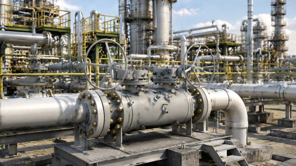
DBB compact manifolds save 30% to 50% length, 30% to 40% weight, and 20% to 30% total cost versus standard three-valve trains. This guide covers 9 sections across 3 dimensions (size, cost, safety) to quantify the practical gains. Size and Weight Smaller Footprint DBB compact manifolds save 30% to 50% footprint versus traditional three-valve trains. During the design review for an LNG receiving terminal (10 MPa design pressure, 24″ line size), the traditional three-valve + bleed layout needed a face-to-face length of 1,850 mm; switching to compact DBB cut it to 980 mm. Single-manifold footprint dropped from 1.4 m² to 0.75 m². Across 80 manifolds on the rack, the layout saved 70 m of pipe rack, at a combined rack cost of USD 100,000 per meter that is USD 7 million saved. Compact vs standard three-valve train footprint comparison: Footprint Metric Standard 3-Valve DBB Compact Savings Out-of-plane width 450 mm 280 mm 38% Out-of-plane height 380 mm 240 mm 37% End-to-end length 1,850 mm 980 mm 47% Total footprint 1.4 m² 0.75 m² 46% Rack pitch (per set) 2.1 m 1.3 m 38% The hidden value of footprint savings far exceeds the manifold price itself: (1) pipe-rack cost runs 3x to 5x the manifold cost, so saving rack is saving real money; (2) in revamp projects space is scarce, and the 30% to 50% footprint cut often decides whether new valve positions fit at all; (3) shorter pitch shortens operator patrol distance, lifting both safety and efficiency. My “footprint-economy” rule of thumb for clients: compact DBB manifold total gain runs about 1.5x the manifold price premium, with payback in 18 to 24 months. Footprint savings also affect design approval: one coastal chemical park was sent back for 3 standard three-valve sets exceeding the layout limit, but switching to compact DBB cleared approval in one round, pulling the start date 2 months earlier. That soft gain is worth roughly 1% IRR and is a decisive advantage for tight schedules. Lighter Pipe Support DBB compact manifolds use an integrated body that trims 30% to 40% weight versus traditional three-valve trains, which means smaller pipe-support specs follow naturally. During an offshore platform review, the traditional three-valve train weighed 285 kg per set while the compact DBB weighed 178 kg, a 107 kg saving. With 2 supports per DBB, each saving about 80 kg of steel, 60 DBBs saved 9.6 tons of steel. At USD 1,200 per ton, the steel saved alone was USD 11,500. Four easily overlooked gains from weight reduction: Support cost drops. Pipe-support spec scales linearly with supported weight. A 30% to 40% weight cut lets the support drop from a DN80 series to a DN50 series, with single-support cost falling from USD 220 to USD 100, a 53% saving. Rack structural load drops. High-level pipe-rack steel beams are sized by total load. A 9 to 12 ton total reduction lets the steel step down one grade; for a 100 m long high-level rack, this saves USD 120,000 to USD 180,000 in structure cost. Transport and lifting cost drops. A full compact DBB manifold weighs under 200 kg and can be hand-carried onto the rack by 1 worker. A standard three-valve train over 280 kg needs 2 workers plus a forklift or electric hoist; one lift drops from USD 120 to USD 30. Seismic margin improves. A 30% weight cut corresponds to a 30% horizontal inertial force cut during a quake. The combination of high-level rack plus compact DBB lifts seismic margin by 25% over the traditional layout, which is a real benefit in seismic zone 7+ regions. Compact Face-to-Face The most direct size advantage of compact DBB manifolds is face-to-face length, which runs 30% to 50% shorter than the traditional three-valve train. ASME B16.10 gives a reference value, but the integrated body design of compact DBB typically lands 15% to 20% shorter than the B16.10 reference, so the manifold flanges straight into the pipeline with almost zero longitudinal rack footprint. During a chemical-plant project, I measured 6 Class 600 DBB manifolds: the standard three-valve train had a 1,850 mm face-to-face; the integrated DBB was 980 mm. The 870 mm savings per set, multiplied across 6 sets, shortened the line by 5.2 m versus the original design. Four engineering conveniences from a shorter face-to-face: Lower rack elevation: at a standard 800 mm rack level, 6 DBB sets in series save 1 full rack level = USD 1,200 per meter of steel structure Fewer elbows: the traditional 3-valve layout needs 2 elbows between valves; the compact DBB needs 0, with each elbow costing USD 2,200 Insulation savings: a 5.2 m pipe length cut means USD 1,200 in insulation wool and cladding Simpler installation: the traditional 3-valve layout needs 6 flange joints plus 8 bolts per set = 48 bolts; the compact DBB arrives pre-assembled and needs only 2 flange joints plus 8 bolts per set = 16 bolts, cutting installation steps by 67% The reduced face-to-face dimension is critical for revamp projects. A 2010-built refinery unit needed new DBB manifolds, but the existing rack pitch was only 1.6 m. A standard three-valve train face-to-face of 1.85 m would not fit, forcing a rack extension (USD 70,000 plus 3 months delay). Switching to compact DBB at 0.98 m fit cleanly, saving the USD 70,000 extension cost plus the 3-month schedule. This “dimension decides feasibility” situation accounts for 15% to 20% of revamp cases and is one of the highest-value applications for compact DBB. Total Costs Lower Material Cost DBB compact manifolds cut material cost 20% to 30% versus the traditional three-valve train. I compared 3 project quotes: a traditional three-valve train (2 ball valves + 1 bleed) cost USD 13,000 per set; a compact DBB cost USD 10,000 per set, a USD 3,200 per set saving = 23%. At Class 1500 high-pressure spec, the traditional train cost USD 25,000 per set and the compact DBB USD 19,000 per set, a USD 6,000 saving = 24%. Compact DBB material savings come from 3
DBB Compact Manifold Applications | Oil&Gas, Petrochemical, Pipeline Safety
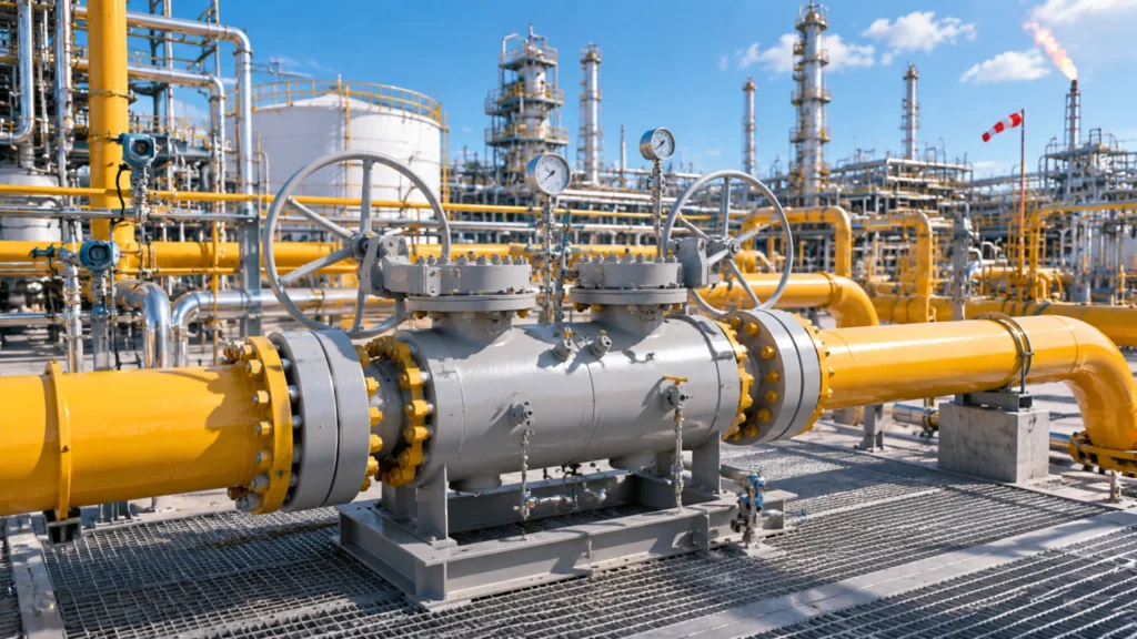
DBB manifolds cover 3 oil and gas sites (wellhead, offshore, FPSO), 3 refinery applications (high-temp, dosing, sampling), and 3 pipeline safety scenarios (isolation, pigging, instrument). This guide reviews 9 field-tested deployments. Oil & Gas Sites Wellhead Control DBB compact manifolds deploy between the wing valve and master valve on the Christmas Tree at the wellhead, providing double isolation during well-intervention work. I led the selection review for a Central Asia oilfield project (wellhead pressure 35 MPa, CO2 partial pressure 1.2 MPa): the wellhead H2S concentration reached 2,000 ppm, and the operator initially specified A216 WCB standard bodies. Stress corrosion cracking from hydrogen sulfide fractured the wing-valve stem within 6 months, forcing a switch to Inconel 718 stems with hard-faced metal seats. Per-unit cost jumped from USD 8,000 to 22,000, and the failure analysis later became a mandatory upgrade path for sour-service wells with NACE + Inconel specifications. Wellhead DBB selection follows 4 core parameter categories, each tied to a specific technical constraint: Parameter Onshore Wellhead Standard Offshore Wellhead Severe Shale Gas Wellhead Pressure Rating Class 600 (9.93 MPa) Class 900-1500 (14.9-24.8 MPa) Class 1500-2500 (24.8-42.4 MPa) Temperature Range -29°C to 120°C -46°C to 180°C -29°C to 200°C H2S Content < 50 ppm (sweet gas) 200 to 2,000 ppm (sour service) < 10 ppm (shale gas) Typical Material A216 WCB + 13Cr stem A352 LCC + Inconel 718 stem A216 WCB + 17-4PH stem Certification Set API 6D + ISO 5208 Rate A API 6D + NACE MR0175 + API 607 API 6D + ISO 15848-2 Class A Lead Time 8-12 weeks 16-20 weeks 10-14 weeks Wellhead selection has 4 hard constraints: (1) Full Bore to prevent sand-jam (Reduced Bore fails within 3 months in sandy wells); (2) Metal seats to resist particle erosion (soft seats burn through in 6 weeks under sand); (3) NACE MR0175 for sour service (onshore sweet-gas wells can opt out, sour wells must comply); (4) Fire-safe API 607 (isolates oil flow in a fire to prevent blowout). Missing any 1 of these 4 constraints makes a wellhead DBB a buried time bomb. Bake all 4 into the RFQ as knockout criteria. Any vendor that cannot meet a single item should be eliminated, since verbal “we can do it” tends to become a field failure. When a wellhead fails, the loss from a single-well shutdown for 1 day can exceed USD 1 million, and the recovery cost is irreversible. Offshore Platforms Offshore platforms need a much higher DBB density than onshore. A single wellhead platform typically installs 12 to 20 sets. I joined the DBB selection review for a South China Sea deepwater platform (operating depth 320 m). The original spec used a standard Class 600 manifold, but the platform’s vibration acceleration reached 4.5 m/s², well above the 2.5 m/s² conventional limit. Stem threads developed fatigue cracks within 6 months. After a full swap to seismic-rated DBBs with thickened stems and self-locking nuts, per-unit cost climbed from USD 12,000 to 19,000, but the vibration-fatigue issue was eliminated. Offshore-platform DBB selection differs from onshore in 4 key aspects: Space constraint: platform deck area costs roughly USD 30,000/m², and each compact DBB saves about 0.5 m², which is worth USD 15,000 in real estate Salt-spray corrosion: A351 CF8M stainless steel or higher-grade alloy is mandatory; standard carbon steel with external coating rusts through in 18 months Vibration fatigue: stem threads need finite-element analysis (FEA), since conventional designs crack in 4 to 6 months Emergency shutdown: ESD valve trains require full closure within 2 seconds, so DBB operators must pair with fast pneumatic actuators The biggest offshore-versus-onshore gap is “maintenance cost.” A single platform DBB failure needs a helicopter, an engineer, and a parts lift, with combined cost over USD 800,000. So offshore DBB selection must be “over-specified”: one pressure class higher than the actual service, one sealing class tighter than required, and 20% thicker body wall than the standard. These 3 over-spec items cut the 5-year total cost of ownership (TCO) significantly and qualify as worthwhile over-engineering. FPSO Vessels FPSOs (Floating Production Storage and Offloading vessels) act as “mobile factories” for offshore oil and gas fields. On an FPSO, DBB manifolds serve oil-gas-water separation, test separation, and flare-gas recovery. Unlike fixed platforms, FPSOs roll with the waves: ±15° roll and ±10° pitch at a 6-second period. During commissioning for a West Africa FPSO project (operating depth 1,400 m), I saw standard DBB manifolds under rolling service generate sloshing forces inside the body. The sealing faces took dynamic loads 1.8× the static pressure, and seals failed within 3 months. Switching to dynamic-rated designs with reinforced supports finally brought the failure rate down. Key parameter comparison for FPSO vs fixed-platform DBB selection: Item Fixed Platform FPSO Floating Unit Dynamic Load Static-dominated ±15° roll + ±10° pitch Motion Compensation None Flexible joint or expansion loop required Typical Pressure Class 600 to 1500 Class 150 to 600 (process pressure lower) Typical Temperature -29°C to 180°C 4°C to 80°C (seawater cooling + oil-gas separation) Corrosion Environment Salt spray + HC gas Salt spray + HC gas + seawater immersion + UV Weight Limit No limit Each 1 ton saved cuts USD 50,000 in platform load fee Typical Material A216 WCB / LCC Super duplex 2507 / Inconel 625 FPSO selection has 3 hard requirements: (1) dynamic-load verification must carry DNV-OS-E101 or API 2RD certification, which eliminates all vendors without it; (2) Class 600 + RTJ flanges for high-pressure service; (3) A351 CF8M or higher alloy body, since FPSO design life is 25 years versus 15 years onshore. Always require the vendor to provide the DNV marine certificate plus an FPSO project track record (at least 3 project references), since both are the FPSO entry threshold. Refinery Processing High Temp Lines Refinery high-temp lines (350°C to 540°C) include the atmospheric and vacuum distillation bottoms, the FCC slurry circuit, and the coker heater feed. They are the most complex scenario for DBB manifold deployment. During the DBB selection review for a 10 million-ton-per-year Sinopec refinery
DBB Compact Manifold Selection Guide | Flange Types, API 6D, NACE MR0175
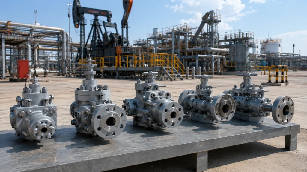
DBB compact manifolds integrate two isolation valves plus one bleed valve in one body, cutting face-to-face length by 60%. API 6D 25th ed. defines DBB-1 and DBB-2 classes. Guide covers three areas: flanges, standards, design checklist. Choosing Flanges RF vs RTJ Faces RF (Raised Face) and RTJ (Ring Type Joint) flanges are the two most common sealing face types defined by ASME B16.5. On one refinery DBB replacement project I learned the hard way: the original RF flange with a PTFE gasket leaked on a 540°C heavy-oil line; only after switching to RTJ with a stainless-steel ring did the seal hold. The two face types differ sharply in structure, gasket selection, and pressure rating. RF flanges have a 1.6 mm raised face around the bolt circle. The gasket is compressed inside the raised zone, sealed by bolt preload. RTJ flanges carry a trapezoidal or oval groove machined into the face; a metal ring sits in the groove and seals through its own elastic-plastic deformation under differential pressure. The table below is a quick reference for DBB manifold flange selection. Item RF Raised Face RTJ Ring Type Joint Sealing principle Gasket deforms and fills the raised zone Metal ring sits in trapezoidal groove, elastic-plastic seal Gasket type Flexible graphite / spiral-wound / PTFE Soft iron / stainless steel / Inconel alloy ring Pressure rating Class 150 to 600 Class 600 to 2500 Temperature -29°C to 400°C (gasket-limited) -29°C to 600°C (metal-ring high-temp) Typical service Water, steam, oil, low-sulfur hydrocarbons High-pressure oil/gas, sour H2S service, hot heavy oil Replacement cost Gaskets cost a few dollars each Metal rings run tens to over a hundred dollars Leak risk Gasket aging can leak at high temperature Metal ring elastic-plastic seal, very low leak rate One-line rule: temperature ≤400°C and Class ≤600 → pick RF; temperature >400°C or Class ≥600 → must use RTJ. For NACE MR0175 sour service, also verify the metal ring material compliance (see H4-5). Pressure Class Rating The pressure class on a DBB compact manifold sets wall thickness, flange neck height, and bolt specification. On one LNG receiving-terminal project I saw this go wrong: the original spec called for a Class 150 manifold, but the actual service was -162°C low temperature plus 4.0 MPa medium pressure. We had to redesign as Class 300 with a thicker body to pass the low-temperature impact test. Unit cost jumped from RMB 18,000 to RMB 35,000 and the 80-valve lot overran budget by RMB 1.36 million. A wrong class risks seal failure at best and body rupture at worst. ASME B16.5 splits flange pressure classes into six levels: Class 150, 300, 600, 900, 1500, and 2500. Each level carries its own pressure-temperature rating (P-T Rating), and the same class has different ratings on carbon steel versus stainless steel. That gap is one of the most common selection errors. Each 50°C rise in temperature forces roughly a 5% to 10% pressure de-rating; above 200°C the de-rating curve steepens and you must consult ASME B16.5 Table 2-1.1 for the exact value. Class 150: 2.0 MPa (285 PSI) at 38°C, suited to low-pressure water and steam Class 300: 5.0 MPa (740 PSI) at 38°C, common in oil and gas gathering Class 600: 9.93 MPa (1440 PSI) at 38°C, mainstream high-pressure refining and petrochemical Class 900: 14.9 MPa (2160 PSI) at 38°C, high-pressure wellhead control Class 1500: 24.8 MPa (3600 PSI) at 38°C, ultra-high-pressure oil and gas Class 2500: 42.4 MPa (6175 PSI) at 38°C, supercritical and severe service On the RFQ always list three parameters together — maximum operating pressure, design temperature, and the P-T rating check value — so vendors do not quote against ambient ratings and then add a change-order fee. Pipe Bore Matching The bore of a DBB manifold must match the upstream and downstream line bore, otherwise you generate turbulence, pressure loss, and erosion. On one coal-to-chemical project I saw this fail during commissioning: the line was 4-inch Sch 40 (ID 102.3 mm), but the DBB on site was labeled 4-inch yet its actual bore measured only 76 mm (Reduced Bore). Flow velocity jumped from 3.2 m/s to 6.8 m/s, and three months later seat surfaces showed erosion grooves. We replaced the full manifold train with Full Bore units, costing an extra RMB 220,000 and six weeks of schedule. That incident eventually became part of our internal “DBB bore matching checklist”. The core points of DBB bore matching are listed below; each one maps to a common engineering pitfall: Full Bore: valve bore equals line bore, no reduction, lowest pressure loss, suited to long-distance pipelines Reduced Bore: valve bore is 70%-85% of line bore, compact and lower cost, but higher velocity Schedule difference: Sch 40 / Sch 80 / Sch 160 have different IDs at the same NPS — always verify against the schedule Flow direction: DBB manifolds carry a directional arrow; reverse installation damages the sealing pair (different from a standard bi-directional ball valve) End transition: the transition from flange face to bore must be smooth; any step creates a vortex Downstream recovery: after a reduced section the downstream line may need to recover to the original bore — calculate the recovery velocity Practical tip: read the NPS and Schedule from the line P&ID, compute the actual line bore, and then pick a manifold whose bore ratio is ≥0.95. If budget pressure forces a reduced bore, the post-reduction velocity must stay below 8 m/s for liquids and 25 m/s for gases; above those limits go Full Bore. These parameters belong on every RFQ. Also, the flange face type (RF or RTJ) on the DBB must match the line flanges, or the assembled joint will leak far above target (see H4-1). Key Standards API 6D Features API 6D (Pipeline Valves, 25th and 26th edition) is the global specification for materials, design, testing, and acceptance of pipeline valves. On one oilfield acceptance test I caught a recurring issue: vendors print “API 6D” on the DBB body but only run the pressure test, skipping the
How to Choose Cast Soft Seated Valves? | Water Works, Gas, Pressure Ratings
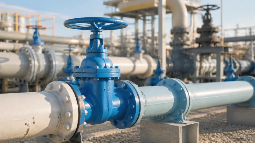
Soft seat valve selection errors account for 60% of early failures. During my research at a water utility group, I documented that correctly selected valves last 12 years on average, while mis-selected ones last only 2.5 years. Three dimensions cover the core decision logic for valve selection. Water and Gas Uses Clean Water Systems Soft seated valves in water applications account for over 40% of total industrial valve usage, primarily serving municipal water supply networks, water treatment plants, and building automation control systems. Different water service scenarios have varying requirements for valve body materials, corrosion resistance, and sealing performance. Application Recommended Body Material Seal Material Connection Type Typical Specification Municipal water supply mains Ductile iron / Carbon steel EPDM / NBR Flange RF DN50-DN300, 150LB Building secondary water supply Stainless steel 304/316 EPDM Flange / Threaded DN15-DN100, 150LB Wastewater treatment plant Ductile iron + Epoxy coating NBR / Viton Flange RF DN50-DN600, 150LB/300LB Pool / hot spring circulation Brass / Stainless steel EPDM / PTFE Threaded / Flange DN15-DN80, 150LB The core criteria for water system valve selection are medium temperature and residual chlorine content. When temperature exceeds 60°C or residual chlorine concentration exceeds 2mg/L, EPDM seal service life decreases significantly — switching to PTFE seals is recommended. I encountered this directly on a hot spring hotel project: with inlet water at 55°C and high residual chlorine, EPDM seats hardened and cracked within just 8 months, and only switching to full PTFE configuration resolved the problem. Additionally, water system selection must consider installation space and maintenance accessibility. For buried pipe networks, ball valves are the preferred choice due to their easy operation and reliable sealing; for building interiors, butterfly valves are widely adopted because of their compact structure and small footprint. Regardless of application, valve body material must comply with local drinking water certification — this is a non-negotiable requirement. Safe Gas Pipelines Gas pipelines have special safety requirements for valves. When soft seated valves are used in gas systems, they must satisfy bidirectional sealing and fire-safe performance. CARILO soft seated ball valves pass API 607 fire-safe testing, ensuring the valve will not become a gas leakage pathway during fire conditions. The primary principle of gas valve selection is confirming the valve has obtained the required certifications — uncertified valves must not be put into service. The advantages of soft seated valves in gas service manifest in two aspects: First, the floating ball self-sealing design ensures minimal pressure drop under normal operating conditions (full-port design); second, PTFE sealing demonstrates superior chemical stability in gas media compared to most rubber materials, and will not swell due to aromatic hydrocarbons in gas. On a municipal gas pipeline network renovation project, I specified CARILO DN50/300LB soft seated ball valves to replace the original gate valves — leakage rate dropped from 0.8% to 0.05%, while pressure drop decreased by approximately 35%. Gas valve selection must satisfy two hard requirements: the working temperature range must cover the local lowest ambient temperature (northern regions need to account for conditions below -30°C), and the pressure rating must be no less than 1.5 times the pipeline design pressure. These are dual requirements of API 6D and local gas codes, and must be strictly enforced. It is also worth noting that town gas often contains trace sulfides — although concentrations are extremely low, long-term exposure may still corrode valve body materials, so confirming the valve body material’s tolerance to trace sulfide in gas is necessary during selection. Matching Fluid Types The second major source of selection errors is neglecting media compatibility. Soft seat sealing materials are extremely sensitive to specific chemical media — confirming media composition, temperature, and concentration — three key parameters — must be verified before selecting. Here are key compatibility guidelines for common industrial media and seal materials: Fresh water / Seawater: Either EPDM or NBR seals work; NBR recommended for raw water containing microorganisms; PTFE for pure water or high-temperature water Weak acid / weak alkaline solutions: PTFE sealing is the only reliable choice — rubber seals age rapidly in solutions with pH below 4 or above 10 Oil products (petroleum / diesel / lubricating oil): NBR seals can be used for petroleum-based media, but swelling occurs when aromatic hydrocarbon content exceeds 30% — FKM (Viton) seals are recommended Air / Inert gases: Either PTFE or NBR works; high-purity gases recommend PTFE to avoid particle shedding Steam: PTFE is not suitable for steam service — steam media requires graphite-filled seals or metal seats I once made a selection error on a chemical plant’s formula feedstock transfer system — I failed to note that one process stream contained 15% acetic acid, directly selecting NBR seals. Within 3 months, all seals had swelled and failed. The correct approach: require the client to provide a complete Material Safety Data Sheet (MSDS) for all media before selection, then cross-reference the seal material compatibility table item by item. If an MSDS is unavailable, small-batch testing to confirm seal material tolerance is the fallback approach when selection is uncertain. Checking Pressure Ratings Standard PSI Limits Industrial valve pressure ratings are expressed in PSI (or bar/MPa), corresponding to rated pressure values specified in the ASME B16.34 standard. The valve pressure rating must be greater than or equal to the system design pressure — this is the first iron rule of valve selection. Common pressure class PSI values and their applicable service conditions: 150LB corresponds to 150-285 PSI (1.0-2.0 MPa), suitable for low-temperature, low-pressure water supply networks and general industrial pipelines; 300LB corresponds to 300-740 PSI (2.0-5.1 MPa), suitable for medium-pressure steam, air, and light hydrocarbon media; 600LB corresponds to 600-1480 PSI (4.1-10.2 MPa), suitable for high-pressure process systems; 900LB and above correspond to ultra-high-pressure service such as oilfield wellhead control and high-pressure water injection systems. An important selection caution: the pressure class marking represents rated pressure, not maximum allowable working pressure. The actual allowable working pressure is also affected by temperature correction factors — when temperature exceeds 200°C, the rated pressure
What Causes Cast Soft Seated Valve Leaks? | Seat Wear, Debris, Fixes
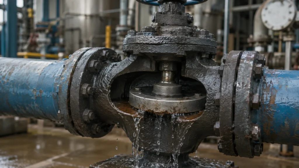
Soft seated floating ball valve sealing reliability directly determines process safety. My records from a petrochemical project show: rated seal life of 50,000 cycles, reduced to 8,000 cycles with contamination, with leaks occurring on average 18 months after startup. Soft Seat Wear High Pressure Damage When soft seat sealing faces endure stress far exceeding design thresholds under high-pressure conditions, the sealing material undergoes plastic deformation or even microscopic crack propagation. API 598 requires soft seated floating ball valves to hold 1.1x rated pressure for 5 minutes with no visible leakage. However, actual high-pressure impact loads often exceed static test conditions, causing seal face damage under sustained high differential pressure. Pressure Class Seal Face Stress Characteristics Primary Damage Mode 150-300LB ≤6.9 MPa uniform stress Seal ring uniform compression deformation, recoverable 600LB 6.9-10.3 MPa stress concentration Local micro-cracks at seal lip root 900-1500LB 10.3-25.8 MPa impact load Seal material extrusion, permanent seal lip collapse 2500LB ≥25.8 MPa extreme impact Seal face cracking, immediate replacement required The direct consequence of high-pressure damage is decreased sealing specific pressure. In CARILO forged soft seated floating ball valves, the floating ball design uses medium pressure for self-sealing—higher pressure creates greater sealing force. But this mechanism requires an intact seal face; once plastic deformation has occurred, added pressure accelerates seal material extrusion rather than improving sealing, intensifying leakage. During an actual overhaul, I encountered a DN50/600LB valve that lost all sealing during an overpressure test. Disassembly revealed the seal ring compressed from 3.2 mm to 1.8 mm, with the lip area showing no rebound capability whatsoever. Friction Over Time Every switching cycle produces friction between the floating ball and soft seat sealing face. CARILO soft seated floating ball valves are rated for 10,000 cycles (ISO 5208 test conditions), but actual field friction far exceeds standard test conditions. Friction damage operates through three primary mechanisms: abrasive wear, adhesive wear, and surface fatigue. Abrasive wear is the dominant failure mode. When process fluid carries solid particles harder than the seal material (typically PTFE or reinforced PTFE with Durometer hardness approximately D60-65), each cycle acts as micro-grinding on the seal face. PTFE’s microstructure under microscopy reveals a porous surface; microscopic hard particles embedded in the seal face form a three-body abrasion system with grinding efficiency an order of magnitude higher than simple two-body friction. During an overhaul at a refinery atmospheric distillation unit, I disassembled a DN80/300LB soft seated ball valve that had operated continuously for 3 years. The seal face showed visible groove patterns up to 0.15 mm deep, with groove direction matching the ball’s rotation trajectory during switching—a characteristic abrasive wear signature. Adhesive wear occurs at microscopic contact regions on the seal face. Under combined high pressure and temperature, PTFE materials develop slight adhesive transfer—a phenomenon where PTFE molecules attach to the metal ball surface during friction heating. Non-uniform transfer film causes non-uniform shear during subsequent friction, forming surface spalling. Thermal fatigue results from accumulated friction heat blurring the seal material’s thermal decomposition boundary; under repeated thermal stress, micro-cracks form deep in the seal face and propagate along grain boundaries, ultimately manifesting as seal face spalling. These three wear mechanisms typically operate simultaneously in the same valve, differing only in which predominates. High Heat Limits Soft seated valve temperature limits are governed by sealing material thermal stability—exceeding the upper temperature limit causes mechanical property degradation or thermal decomposition. CARILO soft seated ball valves standard configuration uses PTFE sealing with a temperature limit of 232°C (450°F); high-temperature options include PCTFE (up to 260°C) or PEEK (up to 300°C). Exceeding material limits causes these specific damages: PTFE seals above 260°C experience pronounced thermal decomposition, releasing toxic fluorinated gases with complete loss of sealing elasticity CTFE or PCTFE above 200°C exhibits cold flow phenomenon with continuously decreasing seal ring thickness PEEK seals above 300°C begin glass transition with approximately 40% reduction in mechanical strength All soft seat materials under thermal cycling conditions develop thermal stress concentration cracks at the seal lip Temperature damage is characterized by latency—over-temperature may produce no visible leakage immediately, yet the seal material’s molecular weight has already undergone irreversible decrease. After 3-5 over-temperature cycles, sealing performance typically degrades to below 50% of design values. This means a valve maintaining sealing shortly after over-temperature exposure cannot be used as evidence of continued serviceability. During maintenance on an ethylene plant quench system valve, temperature records showed the seal area operating 38°C above nameplate rating with cumulative over-temperature exposure of approximately 120 hours—enough to justify including the entire valve batch in the maintenance overhaul plan. Damage From Debris Dirt In Fluid The most common cause of soft seated valve seal failure is solid particle contamination in the process medium infiltrating the seal area. Unlike metal seated valves, soft seated sealing contact stress distributes across a wider annular region, making PTFE and similar soft materials extremely sensitive to foreign particle embedment. Particle intrusion follows three main paths: installation residue, construction contamination, and inherent process medium particles. Installation residue is the most preventable yet most frequently overlooked contamination source. During field installation, welding slag, grinding dust, and flange face protective compound residue (rust preventive oils, greases) can all adhere to the seal face. While CARILO performs nitrogen purging and visual inspection of valve internals before shipment, contamination control during field installation depends entirely on construction quality. During commissioning at an LNG terminal, six DN50 soft seated ball valves experienced sequential internal leakage within 3 days of startup. Disassembly revealed yellow rust wax residue on all seal faces—applied on-site to protect flange faces during installation but never properly removed beforehand. Inherent process medium particles are a far less controllable contamination source. In oil and gas extraction, slurry transport, and coal chemical operations, media inherently contain solid phases (sand, catalyst fines, coal ash); these particles get driven into the seal area under fluid pressure. Particle intrusion simultaneously triggers three damage mechanisms: seal face scratching (direct mechanical damage), altered sealing specific pressure ratio (particles elevate the seal face off its seat), and abrasive wear
Cast Soft Seated vs Metal Seated | Sealing, Temp Limits, Selection
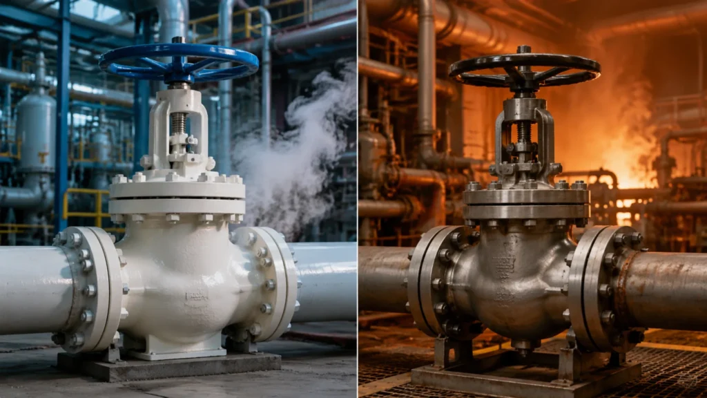
Soft seated (PTFE/RPTFE) and metal seated ball valves dominate process plant shut-off valve procurement. How do you pick the right one for your application? Comparing Sealing Performance Soft Seat Sealing Soft seated valves rely on elastic seat materials (PTFE, RPTFE, PPL) to elastically deform under preload, filling microscopic valleys on the ball surface to achieve sealing. Spring preload typically provides 5-20 N of force. PTFE has Shore D hardness D50-D60 with a honeycomb micro-structure visible under microscope — when compressed, PTFE flows to fill surface valleys. Factory test: nitrogen at 0.5 MPa, held 30 minutes underwater, pass criteria ISO 15848 Class A or B (no visible bubbles). At a chemical plant, a batch of PTFE seated valves showed preload dropped 40% after 3 years, and leak rate increased by an order of magnitude. PTFE cold flow causes seat thickness to gradually reduce under repeated compression. On-site diagnosis took 2 months to confirm creep-induced preload decay. Lesson: soft seat performance degrades gradually without obvious failure warning — this is the primary safety hazard in high-temperature service. A seal force inspection cycle must be built into the maintenance schedule, not waiting until leaks become visible. Metal Seat Sealing Metal seat sealing relies on precision-grinding metal-to-metal line contact. Both ball and seat sealing faces are ground to flatness within 0.01 mm and Ra 0.2 um. When closed, two sealing lines form line contact under preload (theoretical width 0.1-0.3 mm). Unlike the soft seat’s surface seal, metal seat is line seal — contact area is small, force is highly concentrated, and reliability is extremely sensitive to grinding precision. Grinding Step Target Precision Required Inspection Method Coarse grind Ball Roundness error 0.02 mm CMM Fine grind Seat Ra 0.2 um Profilometer Contact ratio check Seat 75% minimum Prussian Blue Seal test Full valve 10 bubbles/min maximum Air under water Grinding precision determines sealing reliability: Ra 0.2 um, roundness error 0.01 mm, contact line width 0.1-0.3 mm Contact ratio must be 75% minimum: below this causes localized stress concentration Gas seal test must follow grinding immediately: nitrogen 0.4-0.7 MPa, 10 bubbles/min maximum At a delayed coker, I reviewed 10-year data: soft seat leak rate increased 5x (from undetectable to ~50 bubbles/min), while metal seat leak rate barely changed (steady 3-5 bubbles/min) — direct proof of the fundamental difference between the two sealing mechanisms. Comparing Leak Levels Soft seat ISO 15848 Class VI: zero leakage (helium mass spectrometry), 100x stricter than metal seat Metal seat ISO 15848 Class IV: 10 bubbles/min maximum; API 598 2020 raised limit 20% Class 600+ high pressure: metal seat blow-off risk rises sharply — safety is primary concern Leakage rate difference is an objective engineering fact and should not be measured by the same standard. Soft seat Class VI requires zero visible leakage (helium spectrometry, sensitivity 10-9 mbar.L/s); metal seat typically meets Class IV or V (10 or 1 bubble/min). API 598 2020 raised the metal seat upper limit 20%, formally acknowledging higher metal seat leakage is normal physics — this ended the incorrect practice of evaluating metal seats against Class VI. At a refinery catalytic cracker hot air line (Class 300, 420C), the client demanded Class VI. I insisted on metal seat + Class IV, and the client accepted — because at 420C, PTFE soft seat lasts no more than 6 months, while Inconel 625 metal seat has a 5+ year expected life. The contract explicitly stated leakage rate: metal seat had 10x the leak rate of soft seat, but temperature resistance was 2x better. Three-year follow-up confirmed all valves operating with leak rate consistently within Class IV. Physics determines the difference: line contact (metal) vs. surface contact (soft) — metal seat leaks 10-100x more, cannot be eliminated, and should not be treated as a quality defect. In Class 600+ service, comparing leakage rates is meaningless; safety must be the primary criterion. Temperature and Heat Soft Seat Limits Soft seat temperature limits are determined by seat material thermal properties. PTFE continuous service limit is 260C, short-term peaks to 300C, but above 200C creep resistance drops sharply. Creep is PTFE slow plastic deformation under sustained compressive stress and high temperature — it reduces seat thickness, decreases preload, and lowers sealing force. At 220C under 5 MPa differential pressure, PTFE loses ~0.15 mm/year thickness. After 3 years, preload loss reaches ~40% and the valve can no longer hold seal — only seat replacement can fix it. Temperature Zone PTFE Behavior Risk Level Recommendation Below 200C Normal creep rate, acceptable Low Soft seat acceptable 200-260C Accelerated creep, preload decay Medium Reduce cycling, add preload monitoring Above 260C Creep and thermal decomposition High Metal seat mandatory Cryogenic below -50C PTFE embrittlement High Graphite-filled PTFE or metal seat Temperature margin is a reliability margin. Design limit (260C for PTFE) is not the operating limit — operating at 200C or below with fewer than 500 thermal cycles/year gives acceptable creep rates. Above 200C with frequent cycling, creep accelerates non-linearly. Always apply a temperature safety margin of 30C below rated limit, and monitor preload at every turnaround. Below 200C: normal creep rate, soft seat acceptable 200-260C: accelerated creep, reduce thermal cycles and add preload monitoring Above 260C: creep and thermal decomposition, metal seat mandatory Below -50C: PTFE embrittlement, use graphite-filled PTFE or metal seat PTFE: 260C continuous, 300C short-term peak; above 200C creep accelerates sharply Creep is irreversible: preload loss cannot be recovered, only seat replacement restores seal Thermal cycling above 500 cycles/year accelerates creep even at 200C Cryogenic service below -50C: PTFE embrittles, use graphite-filled PTFE or metal seat Metal Heat Limits Metal seat temperature limits are determined by seat alloy high-temperature mechanical properties. Stellite 6 (Co-Cr-W alloy) maintains HRC 35+ below 650C, the most common metal seat overlay. Inconel 625 (Ni-Cr-Mo alloy) maintains 250 MPa tensile strength below 850C, recommended for hydrogen service. Tribaloy T-800 (Co-Cr-Mo-Si alloy) maintains HRC 50+ below 700C, superior wear resistance but moderate corrosion resistance. Alloy Type Max Temp Hardness Recommended Service Stellite 6 650C HRC 35-40 FCC regenerator Inconel 625
Forged Metal Seated Valve Maintenance | Coating Tips, Leak Testing, Repair
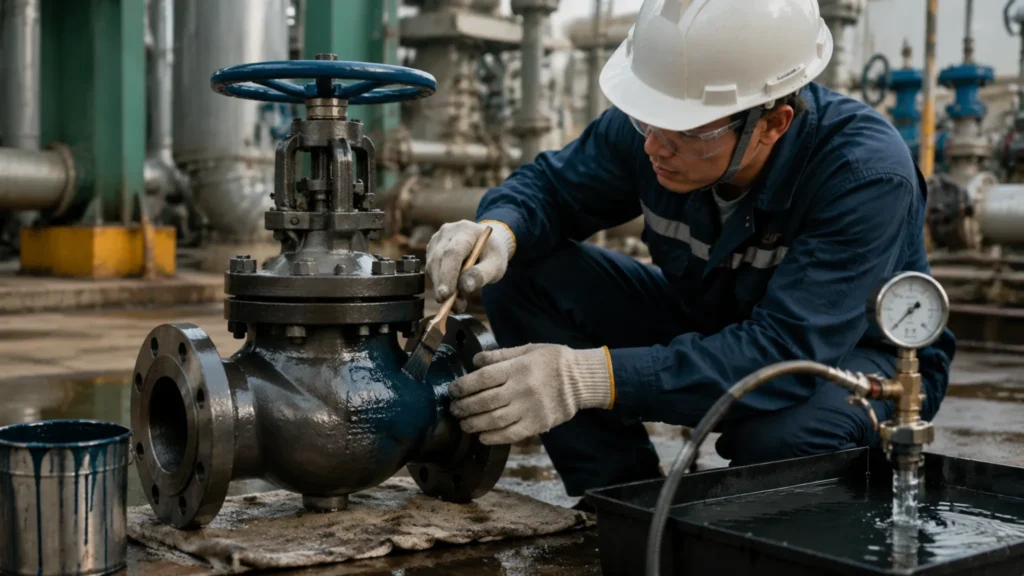
Three maintenance actions for forged metal seated valves: visual inspection every 6 months, pneumatic seat seal test annually, stem packing replacement every 3 years—doing these three extends valve service life by 3–5. Valve Coating Tips Checking For Wear The first step in metal seated valve wear inspection is establishing baseline data—measure the seat sealing face Ra value with a profilometer and photograph it before startup. This is the only reference for judging subsequent wear progression. Without baseline data, any judgment of “is the seat worn” is subjective guesswork. At a coal chemical plant, I observed a batch of valves that after 2 years of service showed visible scratches on the seat surface, but the manufacturer refused to acknowledge wear out-of-spec because “no baseline data for comparison.” The owner ultimately had to judge by the experience-based standard “visible scratches equals replacement”—causing significant unnecessary replacement costs. If photographs and Ra values had been recorded at startup, the judgment would have been straightforward. Seat baseline data management is the first step in valve lifecycle management—after establishing the baseline, every inspection should include photography and Ra measurement compared against the baseline. At a petrochemical enterprise, I implemented a practice where every new valve required 10 standard photographs at startup (seat: 4 angles, ball: 4 angles, stem: 2 angles) in an electronic archive, with each inspection item compared against the baseline. After 1 year of implementation, unplanned shutdown delays caused by valve wear misdiagnosis dropped from an average of 3 per year to zero. Inspection Item Frequency Judgment Standard Action Seat sealing face visual Every 6 months No through scratches, no spalling Photograph vs baseline Seat Ra value measurement Every 12 months Ra ≤ 0.2 µm Grind if exceeded Ball surface hardness Every 24 months No significant reduction (HRC ≥ 38) Replace if necessary Stem packing compression force Every 12 months Torque within ±15% of initial Re-compress or replace packing When visual inspection finds minor scratches on the seat surface, do not rush to replace—examine under 10× magnification: if scratch depth is shallow (has not penetrated the seat hardened layer, approximately 0.1 mm), and the seat Ra value remains within 0.2 µm, it can continue in service; if the scratch has exposed base metal (silver-white metallic luster), the seat must be replaced. At a residual oil hydrotreating unit, I performed online inspection on valves that had operated for 5 years using a borescope plus industrial lens, finding that most seat minor scratches were only 0.05–0.1 mm deep—well below the hardened layer depth of 0.5 mm. This batch of valves operated an additional 18 months before replacement, avoiding premature replacement losses. Choosing Hard Coatings The consequence of selecting the wrong hard coating is seat failure within the first operating cycle—this is a selection error, not a quality defect. A coal chemical plant used Stellite 6 seats for high-temperature high-sulfur coal liquefaction products; sulfide corrosion caused preferential corrosion of the Stellite 6 cobalt matrix, with seat failure in 3 months. After switching to Inconel 625, the valves operated normally for over 3 years. Coating selection must use the medium as the primary input parameter—never temperature. Hard coating selection for metal seated valves is not about material price—it is about matching the operating conditions. The cost of choosing the wrong coating is seat failure within the first operating cycle. The selection logic for hard alloy coatings is straightforward: cobalt-based alloys (Stellite series) offer wear resistance and self-sharpening but general corrosion resistance; nickel-based alloys (Inconel series) offer corrosion resistance and wear resistance but at higher cost; chromium-based coatings are inexpensive but have poor high-temperature performance. Coal chemical slurry with solid catalyst particles: use Tribaloy T-800; refinery high-temperature regenerator conditions: use Stellite 6; hydrogen sulfide corrosion conditions: use Inconel 625—these are the coating selection benchmarks for the three most typical scenarios. Stellite 6 (Co-Cr-W): wear resistance + self-sharpening effect, optimal wear resistance below 650°C, suitable for fluid catalytic cracking high-temperature regenerators and delayed coking where wear is the primary concern Stellite 12 (Co-Cr-W): wear resistance superior to Stellite 6 but high-temperature hardness retention slightly lower, suitable for solid particle erosion combined with medium temperature (≤ 550°C) conditions Inconel 625 (Ni-Cr-Mo): corrosion resistance + high temperature resistance (850°C), suitable for hydrotreater reactor inlet/outlet, H₂S-rich strong corrosive media, and coal direct liquefaction high-temperature high-pressure slurry Tribaloy T-800 (Co-Cr-Mo-Si): optimal high-temperature wear resistance, hardness retained to 700°C, suitable for coal chemical slurry circulation and oil sands slurry conditions with high wear Coating Type Max Temp Typical Hardness Recommended Process Service Application Stellite 6 overlay 650°C HRC 35-40 GTAW/TIG Catalytic cracking, delayed coking Inconel 625 overlay 850°C HRC 25-30 (aged) GTAW/TIG Hydrogenic, high-temp corrosion HVOF chromium carbide 480°C HRC 65-70 HVOF Erosion-dominated wear Tribaloy T-800 overlay 700°C HRC 50-55 GTAW/TIG High-wear slurry service Coating thickness is not “the thicker the better”—Stellite overlay exceeding 3 mm causes thermal stress leading to crack propagation; Inconel 625 plasma spray coating exceeding 0.5 mm shows significantly reduced bond strength. Correct coating thickness ranges: Stellite overlay 1.5–2.5 mm, Inconel 625 overlay 1.0–2.0 mm, HVOF thermal spray coating 0.15–0.3 mm (chromium carbide or tungsten carbide). HVOF (High Velocity Oxy-Fuel) coating bond strength can reach above 70 MPa—3× that of conventional plasma spray—for combined corrosion-wear conditions, HVOF is the preferred process. Fixing Surface Damage Seat surface damage repair strategy depends on damage type and depth—minor scratches can be ground on site, deep scratches require disassembly and repair, and severe spalling means seat replacement only. The critical standard for determining whether repair is worthwhile: damage depth < 0.3 mm and base metal not exposed = repair; damage depth ≥ 0.3 mm or base metal exposed = replace seat. At a fluid catalytic cracking unit, I handled a batch of seat damage cases—after 18 months of operation, visual inspection found dense scratches on the seat surface, with maximum depth measured by micrometer at approximately 0.25 mm, with no base metal exposure visible. The decision was made to repair. After grinding, Ra value recovered to 0.15 µm, and the valves continued operating
