
How to Choose a Cryogenic Ball Valve for LNG Applications | Extended Bonnet Design and Material Selection
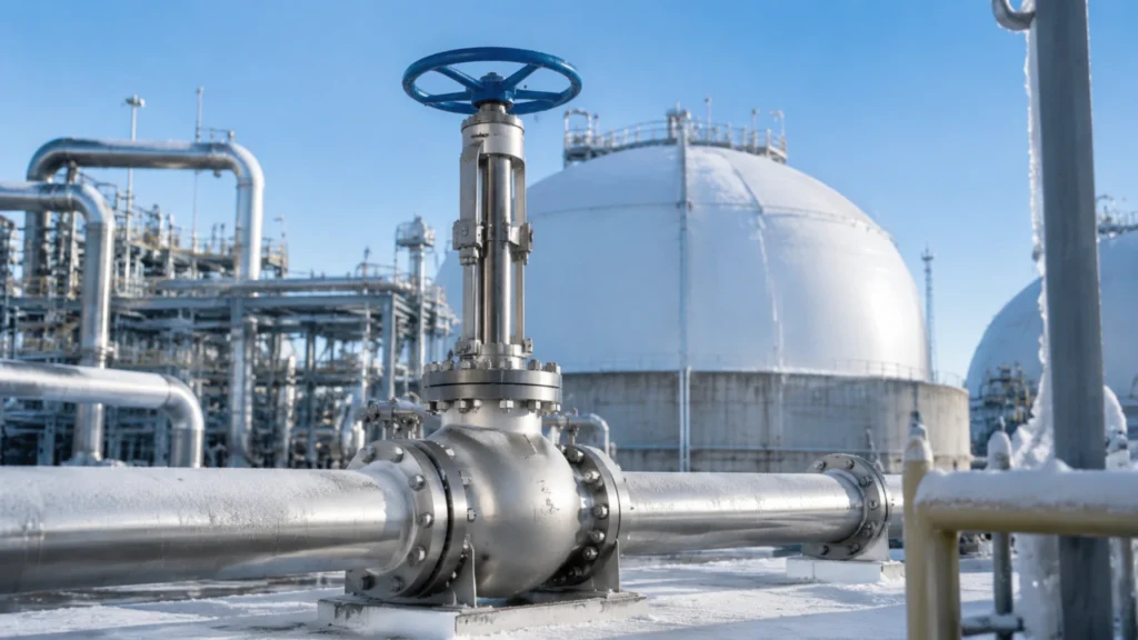
LNG (Liquefied Natural Gas) service imposes stringent low‑temperature requirements on valves: a storage temperature of −162 °C, with instantaneous minimums as low as −196 °C (cargo tank cooling process temperature). The core selection criteria are threefold: The valve body material must maintain sufficient toughness at cryogenic temperatures. An extended bonnet design must ensure the stuffing box remains ice‑free. The seat seal [1] must retain its preload under cold shrinkage conditions. Compliance with BS 6364 [2] or ISO 21011 [3] cryogenic testing standards, together with material certificates in accordance with EN 10204 3.1/3.2, represents the basic delivery threshold for LNG ball valves. LNG Service Characteristics What Does −196 °C Actually Mean? LNG is stored at −162 °C, while the cooling process used in LNG cargo tank construction requires an even lower temperature of approximately −196 °C. This temperature is nearly four times lower than the average Antarctic winter temperature (≈ −50 °C) and about eleven times lower than a domestic freezer (≈ −18 °C). At this temperature, the toughness of conventional carbon steel drops dramatically. Charpy[4] V‑notch impact tests show that the absorbed energy of carbon steel at −162 °C may be only 10–15 % of its room‑temperature value. This is the fundamental reason why special materials are mandatory for LNG service. Methane has a boiling point of −161.5 °C (at atmospheric pressure); the actual LNG service temperature is typically maintained below this value to ensure the fuel remains in liquid form. Should a leak occur, liquid methane at −162 °C will rapidly vaporize, expanding approximately 600 × in volume and forming a highly flammable gas cloud. Valve design must prevent any form of cryogenic leakage. To put −196 °C into everyday context: Liquid nitrogen boils at ≈ −196 °C Liquid oxygen at −183 °C Liquid argon at −186 °C LNG cargo tanks are cooled to −162 °C using a refrigerant cascade technique — pre‑cooling with liquid nitrogen before gradually reaching the target temperature. From a thermodynamic perspective, at −196 °C the average kinetic energy of gas molecules drops to about one‑quarter of its room‑temperature value (77 K vs. 293 K on the absolute scale). This reduction in molecular motion increases gas density and simultaneously causes the lattice parameters of all metallic materials to contract. The linear expansion coefficient of steel is approximately 12 × 10⁻⁶ /°C. From +20 °C to −196 °C, each metre of steel shortens by about 2.6 mm. This shrinkage may appear small, but on the sealing surfaces of a valve it can create a gap of 0.1–0.3 mm between a precisely mated seat and ball — sufficient to cause static seal failure under cryogenic conditions. Design calculations must account for and compensate this thermal contraction. Risk of Cold Brittle Failure Cold brittle failure is the phenomenon in which a metal transitions from ductile to brittle behaviour as temperature decreases. The transition temperature is known as the ductile‑brittle transition temperature (DBTT), and each material exhibits its own characteristic curve. The DBTT of carbon steel (e.g. WCB) lies in the range of 0 °C to −20 °C; at LNG temperatures it is fully within the brittle zone. Brittle fracture is characterised by negligible plastic deformation, a crystalline fracture appearance, and crack propagation speeds that can reach 40 % of the speed of sound — with almost no warning. ASTM A352[5] specifies material requirements for cast steels for pressure‑containing parts at low temperatures: LCB (Low Carbon Steel Cast, Grade B) can be used down to −46 °C LC2 down to −73 °C LC3 down to −101 °C Below these temperature limits, austenitic stainless steels (e.g. 304L, 316L) or aluminium alloys must be used. We personally witnessed a typical cold‑brittle failure at a receiving terminal: a cryogenic ball valve with a WCB body developed a body crack approximately 72 hours after first liquid entry. Investigation revealed that residual moisture from the factory hydrostatic test had not been thoroughly dried; micro‑ice formation through the wall thickness created a stress concentration under −162 °C conditions, ultimately leading to crack propagation in the heat‑affected zone (HAZ) of a weld. This case illustrates that cold‑brittle risk involves not only material selection but also manufacturing process control. ASTM A352[5] LCB‑grade material must undergo Charpy[4] impact testing at −46 °C before shipment, with a CVN[4] (Charpy V‑Notch) absorbed energy of not less than 27 J (average) and 20 J (single value). During site acceptance, the material batch heat‑treatment report and impact test certificate should be verified. Thermal Shrinkage Affects Sealing The thermal contraction of metallic materials cannot be ignored under LNG service. The linear expansion coefficient of common valve materials is about 12–16 × 10⁻⁶ /°C. Taking 304 stainless steel as an example, from +20 °C to −196 °C, the axial shrinkage of a DN100 valve body is approximately 0.35 mm, and the radial shrinkage about 0.28 mm. The seat of a ball valve is typically made of PTFE[6] or PTFE V‑ring seals, whose linear expansion coefficient is about 170 × 10⁻⁶ /°C — more than ten times that of stainless steel. As temperature drops, PTFE shrinks far more than the metal body, causing the preload between seat and ball to decrease. Cryogenic ball valves must employ a “cold preload” technique — the seat preload at room temperature is set higher than required for ambient service, to compensate for the preload loss caused by PTFE shrinkage. Typically, at −196 °C the seat preload should be no less than 60–70 % of the room‑temperature value. In one project, a cryogenic ball valve developed minor internal leakage after commissioning. Inspection revealed a 0.15–0.20 mm gap on the seat seal[1] face. The conclusion: the body shrinkage was within design calculations, but the material of the seat backup ring was improperly chosen — a glass‑fibre‑reinforced PTFE whose shrinkage characteristics differed significantly from those of pure PTFE, causing a larger‑than‑expected overall seat displacement. This case demonstrates that thermal‑contraction compensation must consider the expansion‑coefficient matching of all related components — not just the seat material itself. The cryogenic shrinkage of backup rings, stem packing, and connecting bolts must all be included in the overall seal‑interface gap budget. The extended bonnet design not only isolates the stuffing box from the cryogenic medium, but also — through metallic heat conduction along the bonnet neck — maintains a relatively higher temperature (typically above 0 °C) in the packing area, preventing grease
How to Perform a Factory Acceptance Test for API 6D Ball Valves | Full Witness Test Checklist
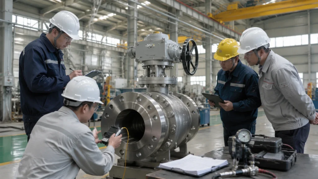
Factory Acceptance Test (FAT) is the final checkpoint for API 6D[1] ball valves from manufacturing to delivery, typically lasting 2–3 days. The purchaser witnesses a series of standardized tests (shell hydrostatic, seat seal, and operating torque – 3 major items) to confirm that the valve materials, performance, and dimensions fully comply with the order technical specifications (based on API 6D-2022[1], API 598-2009[2], and ISO 5208-2008[4] standards). Unlike a document review that only provides certificates, FAT is a “seeing is believing” quality verification – every test data point must be recorded live on site and becomes valid only after signed by the purchaser’s representative or a third-party inspection agency (TPA). This article provides a complete FAT witness test checklist covering pre-test confirmations (3 items), core test items (3 items), and post-test work (3 items) – 9 H4 sections in total – to ensure that ball valve acceptance in international industrial projects (ethylene/propylene plants ≥500,000 tpy, LNG terminals ≥3 million tpy) leaves no gaps and no shortcuts. FAT key parameters quick reference: Shell test pressure = 1.5 × design pressure (API 598[2]); high-pressure seat test = 1.1 × MAWP; low-pressure seat test = 40–50 PSI; hold time: DN≤50 = 15 seconds, DN 65–200 = 60 seconds, DN≥250 = 180 seconds; MTR tensile strength LCB ≥485 MPa, yield strength ≥275 MPa; impact energy ≥27 J at -46°C; torque test covers full stroke at 0–25–50–75–100%. Pre-FAT Confirmations Documentation Review In 2022, we participated in a FAT on site at a 3×0 million tpy LNG terminal and personally witnessed that an inconsistency between the MTR heat number and the stamping on the valve body was discovered during the documentation review, causing the entire batch of valves to be put on hold. This lesson shows: before starting FAT, you must first cross-check the heat number chain – if any link is broken, the process cannot move forward. According to API 6D[1] Section 10 and ISO 14284[4], the FAT documentation package typically includes MTR certificates (ASTM A352[3]/ISO 15156[5]), NDE reports, dimensional inspection sheets, and service condition certification documents – between 8 and 15 items. The one-to-one correspondence must be verified within 2 hours. Required document checklist (API 6D specification): Material Test Report (MTR) – ASTM A352 standard chemical composition report covering carbon, silicon, phosphorus, sulfur, chromium, molybdenum, nickel, etc.; ASTM A370 mechanical properties report including tensile strength (≥485 MPa), yield strength (≥275 MPa), elongation (≥20%), and reduction of area data[1] Charpy V-Notch Report – According to ASTM A352, CVN values for base metal and weld HAZ; LNG service requires a minimum of 27 J at -196°C; API 6D requires low-temperature impact testing on every piece for cryogenic ball valves Non-Destructive Testing (NDT) Report – Any one of RT/UT/MT/PT; 100% weld inspection records with defect rating meeting ASME B16.5 acceptance criteria; RT films must be submitted for valve body pressure-retaining welds Dimensional Inspection Report – Actual measured dimensional tolerances for key components: body, end flanges, stem, ball, seats; flange connection dimensions (bolt hole spacing, face-to-face) deviation must not exceed ±1 mm Pressure-Temperature Rating – Design temperature range (-196°C to +120°C for LNG), rated pressure (Class 150 to Class 2500), material matching design conditions Special Service Certification – API 607/6FA fire-safe type test certificate; ISO 15156 (sour service certification, mandatory when H₂S content >0.01%); NACE MR0175 material compliance statement Traceability Documents – Heat treatment furnace batch records, melting heat trace chain, welder qualification certificates (WPS, PQR, WPQ) Review procedure: Document reviewers (suggested: purchasing technician + quality engineer double-check) execute in the following order: ① Verify PO number, project number, and valve tag number (TAG No.) are consistent across three documents ② Check certificate issue date to ensure it is valid (material certificates are generally valid for 5 years) ③ Confirm that the heat number (Heat No.) covers all pressure-retaining parts: body, bonnet, ball, seat, stem ④ Check dimensional tolerance data against design drawings ⑤ Verify signature completeness: reviewer, approver, and third-party inspection agency (if any) The core principle of the document review stage: every certificate must have a corresponding physical item, and every physical item must be traceable to its certificate. This is the first firewall against “certificate forgery and part substitution.” Common fraud patterns and how to identify them: ① Missing or blurred heat number – genuine MTR heat numbers must match the steel stamp on the actual forging. If the certificate shows “TBD” or “see attached,” immediately start a special verification procedure requesting the original steelmaking record (Heat Chemistry Report). ② Abnormal uniformity of impact energy values – real Charpy test data should fluctuate reasonably (±5~15 J); if all six specimens from the same batch show exactly 30 J (exactly meeting the requirement), this is statistically extremely unlikely and suggests data may have been filtered. ③ RT films do not match weld numbers – request original RT films consistent with the weld map and check them one by one under a film viewer. ④ Missing signatures/stamps on material certificates – EN 10204 3.1 certificates must bear the signature of an authorized inspector (inspector stamp); electronic scans without signatures are not accepted. ⑤ Third-party inspection reports identical to supplier’s self-inspection data – for the same valve batch, the probability of completely identical data between third-party and self-inspection is near zero; if identical, be suspicious. Recommended digital traceability tools: Use ERP/MES systems for heat number barcode matching – scan the actual steel stamp to automatically retrieve the corresponding certificate; API 6D requires the heat number to be marked on the valve nameplate, allowing on-site verification by scanning; IATF 16949 supply chain traceability standards from the automotive industry can be referenced to establish a similar batch traceability system for valves. Document review conclusion signing procedure: After review, the quality engineer completes the “FAT Document Review Record Sheet” stating: conclusion (pass / conditional pass / fail), list of items requiring clarification, and supplier response deadline. Section H4#2 will detail the MTR item-by-item verification procedure. MTR Item-by-Item Verification ASTM A352[3] requires LCB material tensile strength ≥485 MPa (ISO 6892-1[7]), yield strength
How to Specify a Trunnion Mounted Ball Valve for Sour Gas Service | NACE MR0175 Material Requirements
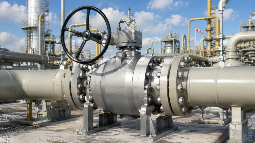
In sour service valve material selection, the standard divides materials into three groups: Group Scope of application Typical materials Group 1 Covers about 80% of normal service conditions Carbon steel, low‑alloy steel Group 2 For non‑welded castings Martensitic stainless steel, etc. Group 3 For nickel‑base alloys Inconel series, etc. The standard strictly prohibits the use of castings that have undergone quench + temper processes (e.g., type 410) because they are very sensitive to SSC. Once, when supplying to an offshore platform, a batch of valve castings had a measured hardness of 238 HB. The client rejected them. We could only release them after lowering the hardness to 231 HB by low‑temperature tempering. Hardness testing is a core index for field acceptance. The common practice is: randomly measure three points on the valve body surface with a portable Brinell hardness tester; the average must not exceed 235 HB. NACE MR0175 does not require materials to pass SSC test certification. However, ISO 15156‑3 specifies that for specific sour service conditions, laboratory testing according to NACE TM0177 is mandatory. Choosing materials that do not meet NACE MR0175 requirements means valves in sour environments face unpredictable, short‑term failure risks. Sulfide Stress Cracking (SSC) — a brittle fracture caused by the synergy of tensile stress and H2S environment. Crack propagation speed can reach millimeters per day, causing spontaneous fracture without any warning. Hydrogen Induced Cracking (HIC) — appears as internal, parallel, laminar cracks in the metal. Even if the outer surface looks completely normal, it can burst suddenly during pressure testing. In 2010, an offshore pipeline failed due to non‑compliant header material, causing a leakage accident with direct economic losses exceeding 200 million RMB. From a procurement compliance perspective, the cost of material selection is the same. Major international oil companies (Shell, ExxonMobil, TotalEnergies) list NACE MR0175/ISO 15156 compliance as a mandatory requirement for supplier qualification. Valves with incomplete material certification or missing test reports are directly rejected. Centralized procurement platforms of CNPC and Sinopec also clearly require suppliers to provide Material Test Certificates (MTC), NACE MR0175 compliance declarations, and third‑party material verification reports. When we supplied valves for a petrochemical project, the client’s procurement department required every single valve to provide a chemical composition and mechanical properties report corresponding to its heat number, not just a general material certificate. This is because actual measured values of castings from the same batch can fluctuate due to differences in heat treatment furnace temperature. Individual reports are the only way to ensure traceability. Material Selection (Valve Body / Overlay / Seals – Three Dimensions) Valve Body Material (A352 LCB/LCC + Impact Energy ≥ 27 J) For cast steel valve bodies in sour service, the first choice is low‑temperature carbon steel per ASTM A352. A352 LCB (carbon steel, minimum service temperature –46°C) and A352 LCC (contains chromium) are the two most common. Their chemical composition requirements are similar; the sulfur limit for LCB is 0.25%, for LCC it is 0.23% – LCC has better weldability. For Class 300 to Class 600 medium pressure, LCB/LCC can satisfy most sour field requirements. For high‑pressure service (Class 900 and above), ASTM A216 WCC (or WCB) is considered, with tensile strength up to 485 MPa or higher. Valve body wall thickness is calculated per ASME B16.34, plus a corrosion allowance (typically not less than 3 mm). Material selection must also pay attention to impact toughness requirements. NACE MR0175 stipulates: at the design temperature, the material’s heat‑treated state must ensure a V‑notch impact energy of no less than 27 J (individual value). A352 LCB is usually normalized or normalized + tempered; actual impact energy can reach 40–80 J, far above the minimum standard. We once found in a low‑temperature ball valve project that the LCB casting impact energy individual value was only 18 J – it failed. Investigation showed insufficient heat treatment holding time; the sulfides were not fully spheroidized. All parts in that batch were returned to the factory for re‑heat treatment, and the holding time parameters were written explicitly into the procurement specification. The surface roughness of the internal flow path (usually Ra ≤ 6.3 μm) must also be noted in the design documents. Valve Seat Overlay Material (Stellite 6 HRC 38–45 + PAW Technique) The valve seat sealing surface is the only part directly exposed to switching friction and media erosion. The choice of overlay material directly determines the valve’s sealing performance and service life. In sour gas service, seat sealing surfaces are usually overlaid with cobalt‑base alloys (Stellite series) or nickel‑base alloys (Inconel 625/718). Stellite 6 (Co‑Cr‑W‑C series) is the most mature industrial choice. Its Rockwell hardness is HRC 38–45, and it has been verified by decades of engineering in H2S environments. Inconel 625 (Ni‑Cr‑Mo‑Nb series) overlay hardness is HRC 25–35. Although lower in hardness than Stellite 6, its high‑temperature corrosion resistance and machinability are better, especially for sour gas media containing CO2. The overlay thickness is usually controlled at 3–5 mm. Too thin – insufficient corrosion resistance; too thick – increased machining difficulty and cracking risk. Main overlay techniques include: PAW (Plasma Transferred Arc Welding) – lowest dilution rate (≤ 5%), uniform overlay composition, first choice for high‑pressure ball valve seats. TIG/GTAW (Tungsten Inert Gas Welding) – good flexibility, suitable for small batches or custom‑shaped seats. SMAW (Shielded Metal Arc Welding) – high dilution rate and unstable quality; rarely used in new projects. After overlay completion, the following inspections are mandatory: Liquid penetrant testing (PT) – confirm no cracks. Hardness inspection – measure three points on the overlay cross‑section; average must meet design requirement. Ultrasonic testing – confirm overlay bond integrity. We once found in a refinery project that the supplier’s TIG overlay layer had vertical fatigue cracks along the filler line. The cause was excessive impurities in the weld material and insufficient preheat temperature. After re‑baking the weld material at 250°C/h and increasing preheat before welding to 150°C, the cracks were eliminated. Seals (FFKM 200°C+ + ISO 15848-1 Class B) Ball valve stem seals (packing)
How to Install a Large Bore Flanged Ball Valve | Alignment, Gasket Selection, Bolt Torque Sequence
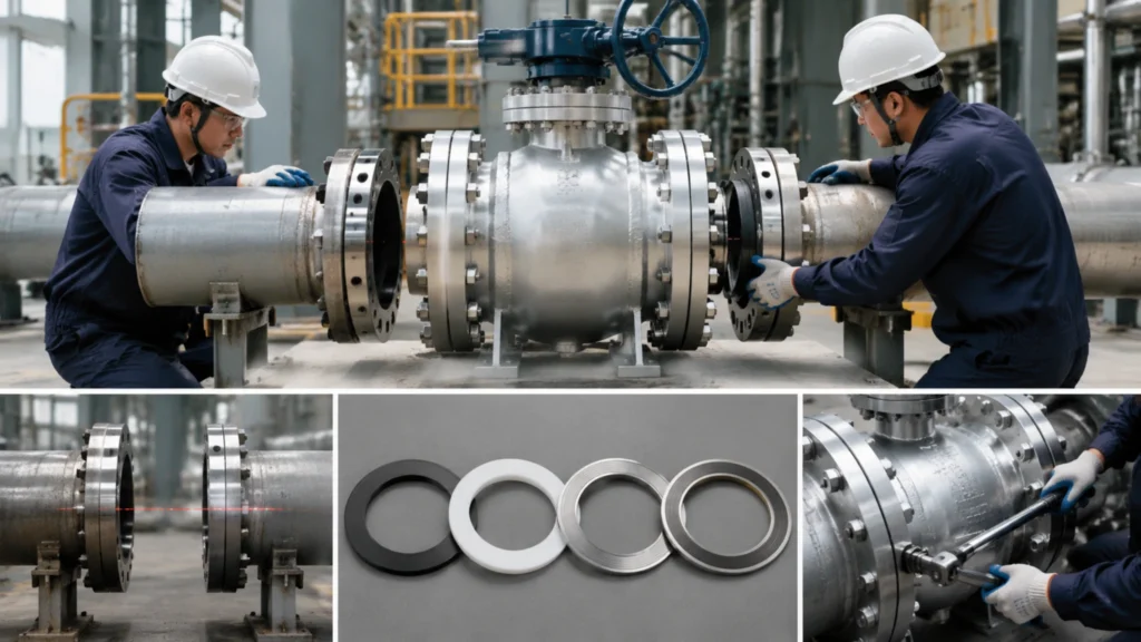
The installation quality of large-diameter flanged ball valves (above DN300, Class 150~Class 600) directly determines the sealing reliability of the pipeline system. Unlike small-diameter valves, large-diameter flange joints require higher bolt preload forces and larger gasket areas. Any procedural deviation will be amplified during high-temperature and high-pressure (Max 550°C / Class 2500) operations. This article systematically outlines the standard installation process for large-diameter flanged ball valves. It covers preparation before installation, installation steps, and post-installation inspection. Five key aspects are included: pipe alignment, flange cleaning, gasket selection, torque control, and pressure test verification.[1] Real case reminder: In the pipeline installation practices of several petrochemical projects, we experienced a typical alignment error firsthand — during the installation of a DN400 Class 600 ball valve in an ethylene cracking unit, a pipe axis deviation of 1.2mm (standard allowable value is 0.8mm) caused the valve body sealing surface to leak after the initial temperature rise. After reworking and replacing the valve body, strictly executing the alignment process described in this article resulted in a zero leakage rate for similar subsequent valve installations.[2] Pre-Installation Preparation Pipe Alignment Inspection Key data: Over 60% of large-diameter flanged ball valve installation failures occur during the pipe alignment stage.[3] If there is an angle or offset on the pipeline flange faces, forced assembly will directly damage the valve body sealing surface, or even cause the valve stem to bend or break. Face Runout (≤0.8mm) vs. Shaft Misalignment (≤0.8mm) Pipe alignment inspection needs to focus on two indicators simultaneously: Face Runout and Shaft Misalignment. The ASME B16.5 standard[4] stipulates that the concentricity deviation of Weld Neck flanges should be ≤0.8mm; the gap between mating flange sealing surfaces should be ≤0.8mm. For field operations, it is recommended to use a steel ruler or feeler gauge for initial inspection: Fit the steel ruler to the outer edge of the flange and measure four points (0°, 90°, 180°, 270°). Insert the feeler gauge blade between the two flange sealing surfaces. The difference in readings is the parallelism deviation.[5] Handling Deviations When the deviation exceeds the allowable value, it is strictly prohibited to forcibly pry the valve body to correct the deviation. The correct approach is: add adjustment shims on the pipeline side (not the valve side), or re-cut the pipeline joints. Important regulation: The EN 1591 flange design standard[6] explicitly requires: it is prohibited to use the valve flange holes as lever fulcrums to apply force (refer to API SPEC 6D specification). Flange Face Cleaning Contaminants on the flange sealing surface are the leading cause of static seal failure. Rust, welding slag, lubricating oil, and dust particles can each embed into the gasket during the compression process, forming micro-channels for leakage.[7] Standard Cleaning Steps Remove rust and slag: Use a steel or copper wire brush to remove welding slag and rust around the outer edge of the flange and bolt holes. Focus on cleaning the inner walls of the bolt holes (where foreign objects are most likely to accumulate).[8] Purge: Use oil-free compressed air (OAF) to blow the flange sealing surface and remove loose particles. Degrease and wipe: Wipe the sealing surface with a degreaser (such as acetone or professional flange cleaner), and immediately dry it with a dry non-woven cloth after removing the grease.[9] Inspect and refinish: Use a vernier caliper to check the sealing surface for scratches, pits, or pitting. If necessary, lightly grind with fine sandpaper (320 grit or above) and clean again. The sealing surface roughness should reach Ra 3.2µm~12.5µm; the ISO 1302 standard[10] has specific requirements for surface texture grades. Note: The outer edge of the flange must be free of burrs and flashes, otherwise, it will cut the outer edge of the gasket when compressed. How to Select Gaskets Large-diameter flanged ball valves typically use a Spiral Wound Gasket (SWG) + inner ring combination, suitable for a temperature range of -196°C to 550°C.[11] Gasket selection requires comprehensive consideration of four dimensions: pressure rating, medium, temperature, and corrosivity.[12] Gasket Type vs. Pressure Rating Flange Pressure Rating Recommended Gasket Type Inner Ring Material Applicable Temperature Range Class 150 / PN20 Spiral Wound Gasket (SWG) Carbon Steel (CS) -50°C~300°C Class 300 / PN50 SWG + Inner Ring Stainless Steel (SS) -196°C~400°C Class 600 / PN110 SWG + Inner Ring + Inner Ring SS 316L -50°C~550°C Class 900 / PN150 SWG + API 607 Fire Safe SS 316L + Graphite -50°C~550°C About filler materials: Graphite filler: Temperature-resistant up to 550°C, suitable for high-temperature steam systems. PTFE filler: Temperature-resistant up to 260°C, suitable for strongly corrosive acid and alkali media. Mica filler: Withstands high temperatures of 1000°C, but ASME B16.20[13] requires it to be used with an inner ring to prevent oxidative spalling. Diameter recommendation: For sizes above DN300, it is recommended to use SWG with an inner ring. The inner ring plays a role in positioning and preventing blow-out, stopping high-pressure gas from leaking through the gasket’s cross-sectional channels.[14] Installation Steps Bolt Insertion Sequence Bolt insertion (according to ASME B16.5 / API SPEC 6D) is the most easily overlooked yet most impactful step in flange joint assembly. Before inserting bolts, ensure the following: Bolt material matches the flange pressure rating. Nuts are clean and free of burrs. Threads are coated with lubricant (copper paste for high temperatures, graphite oil for normal temperatures).[15] Insertion Operating Standards Start from the bottom of the flange (6 o’clock position). First insert the bottom bolts and tighten the nuts finger-tight, serving as a positioning reference.[16] Then expand upwards following the “alternating left and right” principle: Left → Right → Left → Right… making the flange faces gradually fit and center. After all bolts are inserted, check whether the flange gap is uniform (measure four points with a feeler gauge). If there is significant skewing, it must be loosened and readjusted; forced compression is prohibited.[17] Stud Bolts require flat washers on both ends, and nuts should be installed on the side convenient for torque operation. Prohibited action: It is strictly prohibited to use the valve
How to Select the Right Actuator for an API 6D Ball Valve | Pneumatic vs Electric vs Hydraulic
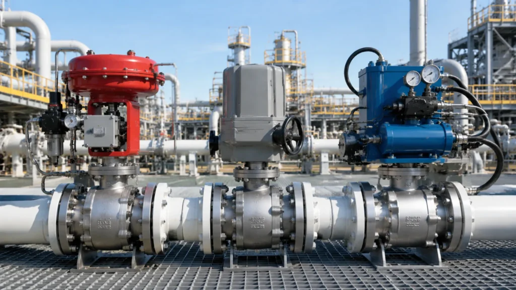
API 6D ball valves are critical isolation equipment in pipelines. Actuator selection directly impacts system operational reliability and construction costs. This guide comprehensively covers valve selection for sizes ranging from DN50 to DN1200 and pressure ratings from Class 150 to Class 900. It provides a comparative analysis of the three mainstream actuator solutions: pneumatic, electric, and hydraulic.[1] Three Types of Actuators To give you an intuitive understanding of the core differences among the three types of actuators, here is a cross-comparison of their key parameters: Actuator Type Typical Output Torque Range Common Switching Speed / Time Best Application Conditions Pneumatic Actuator 50 ~ 3000 Nm 0.5 ~ 3 seconds Oil and gas transmission pipelines, chemical plant explosion-proof zones, and scenarios requiring rapid Emergency Shutdown (ESD). Electric Actuator Depends on power (0.05 ~ 3 kW) 15 ~ 30 seconds (e.g., DN200) Scenarios requiring precise multi-stage adjustment and high opening accuracy control (e.g., desalination, LNG receiving stations). Hydraulic Actuator Easily exceeds 10,000 Nm 8 ~ 20 seconds (e.g., DN800) Large-diameter high-pressure valves (DN700+ / Class 900+), deepwater production, and subsea pipelines. Pneumatic Actuators: Key Characteristics Pneumatic actuators are the most widely used option in oil and gas transmission pipelines. In many station modification projects consisting of DN200 to DN600 pipelines, double-acting pneumatic actuators are uniformly adopted. The conventional air supply pressure ranges from 5 to 8 bar. The output torque spans from 50 to 3000 Nm, which can directly drive the opening and closing of API 6D ball valves. Its action response is very fast, with switching times generally between 0.5 and 3 seconds. This serves as a rigid indicator for emergency shutdown (ESD) conditions requiring instantaneous isolation. Structurally, pneumatic actuators mainly include the following core components: Cylinder Piston Spring Return Mechanism The pneumatic output torque varies linearly with the air supply pressure. For every 1 bar drop in supply pressure, the output torque decreases by about 10% to 15%. Single-acting actuators with spring returns are ideal for “fail-safe positioning” scenarios. For example, in fire and gas systems, if the air supply pressure is suddenly lost, the valve will automatically close via spring force. Core Point to Note: The torque of API 6D ball valves is usually divided into Breakaway Torque (to overcome initial seat friction) and Running Torque (to maintain switching friction). Their values typically differ by 1.5 to 2 times. During selection, the rated torque of the pneumatic actuator must be at least 30% greater than the breakaway torque to serve as a safety factor.[2] High explosion-proof performance and reliability are the core advantages of pneumatic actuators. In flammable and explosive areas with Class IIA/IIB gases, such as chemical plants and refineries, pneumatic actuators do not rely on electricity. They do not produce electric arcs or high-temperature surfaces during operation, allowing them to directly meet the strict explosion-proof requirements of ATEX Zone 1/2 or IECEx Ex d.[4] In contrast, electric actuators contain internal motors and contactors, presenting a certain ignition risk during operation or when the enclosure cover is opened. In addition, air consumption is a factor that must be accurately calculated during selection. For example, a DN300 ball valve requires about 80 to 150 NL (Normal Liters) of compressed air for a single cycle. For high-altitude stations or areas with insufficient local air supply, the system must be configured with an additional air storage tank of sufficient capacity. The disadvantage of pneumatic actuators is their abrupt power characteristics. They generate significant pressure shocks at the moments of starting and stopping, which usually causes slightly greater wear on the valve stem seals compared to electric actuators. In recent years, as pipeline pressures have risen to Class 600 ~ Class 900, the required torque for API 6D high-pressure ball valves has exceeded 5000 Nm. In this case, the size of large pneumatic actuators becomes extremely bulky, and the overall burden on the air supply system becomes too heavy. Therefore, hydraulic solutions should be prioritized. Electric Actuators: Ideal Use Cases Electric actuators are ideal for special conditions requiring precise position control and multi-stage continuous actions. In desalination plants and LNG receiving stations, valves often do not need simple full opening or full closing. Instead, they need to execute multi-step staggered adjustments, such as opening to 25% and holding for 10 seconds, then continuing to open to 50%. Electric actuators integrate high-precision gearboxes and drive circuits internally. Through 4~20 mA analog signals or fieldbus (PROFIBUS/Foundation Fieldbus) communication, the valve can stop precisely at any preset opening, with positioning accuracy controlled within ±1%. Electric actuators do not need to be equipped with complex compressed air systems. They can directly utilize the factory’s existing power supply, saving owners the high initial cost of building dedicated air compressor stations. In a 2023 desalination project in Zhejiang, electric actuators were comprehensively selected because the site lacked the infrastructure for laying compressed air pipelines. In the later commissioning stage, technicians finely adjusted the valve characteristic curves using the HART protocol. They successfully reduced the linear error to 0.8%. Smart Monitoring Advantage: Electric actuators can output and display the current torque value in real time. This provides an early warning for abnormalities such as valve stem jamming, which traditional pneumatic actuators cannot do. When selecting an electric actuator, two key parameters directly determine its performance: Rated Power: The conventional specification power ranges from 0.05 to 3 kW. Greater power yields higher output torque, but the capacity margin of the power supply transformer must be considered. The starting current of high-power actuators is often 5 to 7 times the rated current, which can cause instant shocks to the plant’s power grid. Protection Level: For outdoor installation, IP67 is the basic requirement. However, if the project is in rainy southern regions or coastal salt spray environments, IP68 is strongly recommended, along with an anti-corrosion coating. The motor bearings should also use stainless steel materials. In LNG receiving stations with ultra-low temperature media pipelines of -162°C, electric actuators must be equipped with space heaters to prevent internal condensation. The heater power
How to Interpret a Valve Material Test Report | EN 10204 3.1 Certification, Chemical Composition, Mechanical Properties
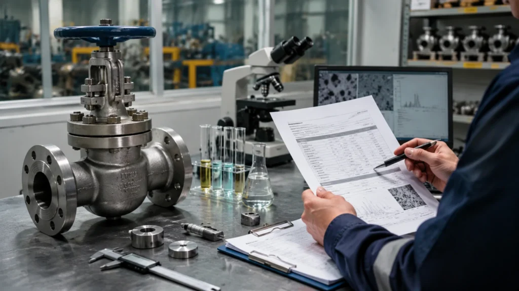
When each valve leaves the factory, a material certificate (EN 10204 3.1) is delivered together with the physical product. It covers key data such as: Property Value / Range Chemical composition 9 major elements plus trace elements Tensile properties Re ≥ 250 MPa, Rm = 485–655 MPa Impact toughness -46°C ≥ 20 J Hardness ≤ HBW 200 Before accepting the goods, the purchaser’s verification of these data is the final quality control barrier. It helps prevent nonconforming materials from entering the installation stage. In 2021, the first batch of 28 ball valves in a petrochemical project suffered valve body brittle fracture after 18 months of operation. The direct losses were more than RMB 3.4 million. What Is an MTR? What Does a 3.1 Certificate Mean? An EN 10204 3.1 certificate is a material inspection report provided by the steel or forging material supplier to the purchaser. It follows the European standard EN 10204:2004. The core meaning is: the material manufacturer has carried out the specified inspections for each delivered product or batch according to the contract or applicable standard. The inspection results have been confirmed and signed by the supplier’s quality department. This department must be independent from the production department. The certificate must include traceability information: Material grade (e.g., A352 LCC, CF8M, or WCB) Specification and dimensions Heat Number Order number Heat treatment condition Applicable material standard number (e.g., ASTM A352/A352M) During an audit of a valve casting supplier in Jiangsu in 2022, I found that the signature section of its 3.1 certificate contained only the signature of the production workshop director. There was no independent confirmation or seal from the quality inspection department. This did not comply with the requirements of Clause 5.1 of EN 10204:2004. Even if the factory seal was affixed, it still did not constitute a compliant 3.1 certificate. The regulatory value of a 3.1 certificate lies in the fact that it serves as a legal document for material conformity declaration. If a material failure occurs during the warranty period after installation, the purchaser can use the 3.1 certificate as evidence to file a quality claim against the supplier. A certificate issued by a noncompliant signing body may be deemed invalid in legal arbitration. What Is the Difference Between 3.1 and 3.2? The essential difference lies in the independence of the inspection body and the confirmation procedure. Aspect 3.1 Certificate 3.2 Certificate Who confirms and issues Supplier’s own quality department Manufacturer’s quality department + purchaser’s designated inspecting officer or third-party agency Scope By production batch (Heat or Batch). Up to 50 pieces from the same batch may share one 3.1 certificate. One independent certificate per piece Signatures required One signature from supplier’s quality department Two independent signatures or seals: one from the manufacturer’s quality department, one from the purchaser or third party Typical cost Approximately USD 80–120 per certificate USD 300–500 per person-day (China); USD 1,000–1,500 per person-day (overseas). Unit cost is usually 5–10 times higher than 3.1. ASME B16.34 and API 600 usually require 3.2 certification for high-pressure and high-temperature valves. For the same batch of ASTM A216 WCB castings, such as 50 DN100 gate valves, the quotation for a 3.1 certificate is approximately USD 80–120 per certificate. A 3.2 certificate involves on-site attendance by a third-party inspection agency, which costs about USD 300–500 per person-day in China and may reach USD 1,000–1,500 per person-day for overseas projects. Therefore, the unit cost is usually 5–10 times higher than that of a 3.1 certificate. In a dispute handled in 2023, the purchaser did not specify the certificate type in the contract. After receiving the goods, the purchaser found that the supplier had provided a 3.1 certificate, while the end client required a 3.2 certificate during acceptance. The supplier refused to supplement third-party confirmation, and the goods eventually had to be replaced, delaying the project by about two months, or approximately 60 days. How to Identify a Fake Report Fake MTRs can be identified from two aspects: document form and data content. Document-form checks (per ISO 10474:2011): Verify the unique certificate number. Each MTR should have a unique number that matches the factory’s internal traceability system. Check whether the supplier’s name and address match the actual factory information. Verify whether the signatory is an authorized quality department signatory. Data content checks: Chemical composition and mechanical property data must fall within the ranges specified by the applicable material standard. For ASTM A352 LCC: C ≤ 0.25%, Mn ≤ 0.70%, P ≤ 0.04%, and S ≤ 0.045%. If the report shows C = 0.28%, it has exceeded the standard upper limit. For tensile properties: Re ≥ 275 MPa, Rm = 485–655 MPa, and El ≥ 22%. If the reported data are exactly close to the lower limits, such as Re = 276 MPa, the data may have been modified. Re = 276 MPa is 26 MPa higher than the standard lower limit of 250 MPa, and normal production variation would not be so precise. ISO 10474:2011 requires the time logic of three traceability documents to be consistent: the raw material warehousing date must be earlier than the heat treatment date, and the heat treatment date must be earlier than the finished product inspection date. If the time sequence among the three documents is contradictory, the credibility of the MTR is basically questionable. For ASTM A352 LCC, tensile properties require Re ≥ 250 MPa and Rm = 485–655 MPa. The yield-to-tensile ratio Re/Rm is usually between 0.55 and 0.70. Data modification is an illegal act. In a 2021 offshore platform project, the supplier’s 3.1 certificate showed an impact toughness of 27 J at -46°C, but third-party retesting showed only 18 J, below the ASTM A352 minimum requirement of 20 J. It was finally confirmed that the supplier had misused the MTR from a previous qualified batch. For ASTM A352 LCC, C ≤ 0.25%, Mn ≤ 0.70%, P ≤ 0.04%, and S ≤ 0.045% are the basis for material conformity judgment. How to Read Chemical Analysis What Do C,
DBB Compact Manifold Maintenance | Seal Replacement, Pressure Test, Life Cycle
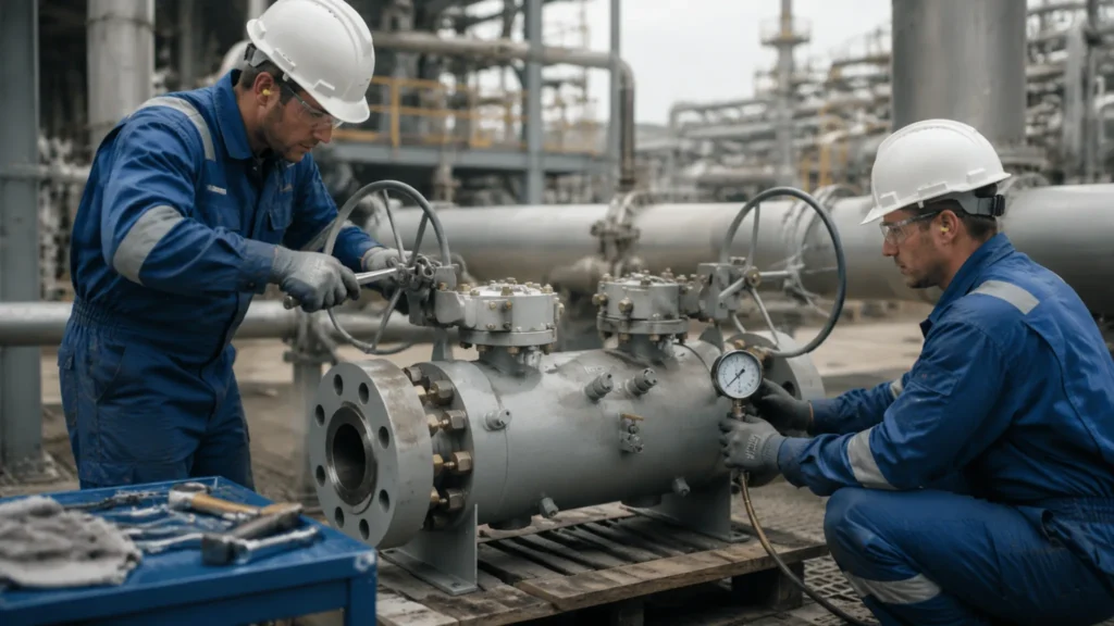
DBB compact manifolds are critical isolation equipment in oil, gas, and petrochemical applications. In Class 600-900 service, seal failures cause costly unplanned shutdowns — proper maintenance cuts this risk by up to 80%. Replacing Valve Seals Checking Seal Damage DBB valve seat seal damage does not occur suddenly; in most cases, the sealing surface has given multiple warning signals before leakage occurs. The first step in checking for seal damage is to determine the current state of the seal and then decide whether a shutdown for maintenance is necessary. Visual inspection is the most direct method. Using a flashlight to closely examine the valve seat sealing surface, a normal elastic seal (made of materials such as EPDM, fluoroelastomer, or polytetrafluoroethylene) should appear intact, continuous, and free of cracks. If a fine network of cracks is observed on the surface, or if there are noticeable gaps or tears on the sealing lip, it indicates that the seal has entered a stage of physical damage, which is irreversible and requires replacement. In 2023, during a routine inspection at a chemical plant’s hydrocracking unit, an operator found a visible 0.3mm crack on the upstream side of the DBB valve’s sealing surface. Due to the timely replacement, an unplanned shutdown caused by high-pressure hydrogen leakage was avoided [1](https://www.emerson.com/us-en/automation/control-valves/double-block-bleed-valve-manifold). Discoloration of the seal surface is also an important warning sign. EPDM material will turn from black to brown and harden under continuous high-temperature conditions (above 130°C); fluoroelastomer will become shiny and sticky after long-term contact with mineral oil. These are typical signs of material aging. The aging of polytetrafluoroethylene seals is manifested by whitening of the surface, the appearance of fine cracks, and increased hardness, leading to a decrease in sealing performance. A petrochemical company recorded the average service life of valve seat seals against operating temperature: for every 10°C increase in operating temperature, the seal life is shortened by approximately 30%—this data comes from the company’s equipment archives from 2019 to 2023. The hardness change of elastic seals can be judged by touch. Using a fingernail to gently press the sealing lip, a normal seal feels soft and elastic, and the fingernail impression will quickly rebound to its original shape. If a noticeable indentation remains after pressing and does not rebound, it indicates that the elasticity has severely decreased, and even if it is not leaking currently, it is on the verge of leaking. This tactile test is very practical for on-site valve inspection without disassembly and does not require any instruments. The inspection of metal sealing surfaces (hard seats) is different from that of elastic seals, mainly focusing on the integrity of the sealing line (seat bore sealing contact line). Using an endoscope to look into the valve body, check whether the sealing line is continuous, and whether there are any signs of erosion, corrosion pits, or foreign object indentation marks. The sealing line width of a DBB valve is usually only 0.5-1.5mm, and any local interruption of the sealing line means a potential internal leakage hazard. In 2022, an endoscope inspection at a natural gas pipeline station found sand particle indentation marks on the DBB valve’s sealing line. After removing the foreign objects and retesting, the leakage rate returned to an acceptable range [2](https://www.swagelok.com/fluid-system-tips/signs-of-valve-leakage). During the inspection, do not overlook the connection sealing surfaces between the valve body and the pipeline. The flange sealing surfaces at both ends of the DBB valve (usually using spiral-wound gaskets or ring gaskets) are the second line of defense against internal leakage. If there are crushing marks on the flange sealing surfaces, gasket extrusion, or if the fastening bolts feel loose (tested by gently tapping with a torque wrench), it indicates that the sealing surfaces have been damaged. In this case, simply replacing the valve seal will not solve the problem; the flange sealing surfaces must also be addressed. The second type of signal for seal damage is functional abnormality—even if no physical damage is seen, changes in valve operating parameters can reveal a trend of deteriorating seal condition. During normal operation of a DBB valve, if the upstream pressure is stable but the downstream pressure shows a slow rise (even if the increase is very small, such as 0.1-0.2 bar), it is often a sign that the valve seat sealing surface has begun to leak internally. This pressure drift is the most difficult to detect in the early stages because the change is slow and can easily be overlooked by operators during routine inspections. It is recommended to install a pressure gauge with an accuracy of no less than 0.5 on both the upstream and downstream sides of the DBB valve, so that pressure changes at the 0.01 bar level can be read. The phase state and pressure level of the leaking medium determine the frequency and focus of the damage inspection. For volatile media (such as light hydrocarbons, liquefied petroleum gas), there may be no obvious dripping after the valve seat seal is damaged during normal operation, but the smell can be detected—this is an effective low-cost detection method. The API 624 standard requires that all DBB valves used in flammable or hazardous media must undergo a factory helium mass spectrometer leak test, with a qualified standard of a leakage rate not exceeding 50 ppmv [3](https://www.api.org/products-and-services/standards). During on-site inspections, if you have an olfactory detector or a portable combustible gas detector on hand, you can first use it to scan the outside of the valve body for any trace gas leakage before deciding whether to disassemble for inspection. The chemical compatibility of the medium is also an accelerating factor for seal damage. The same EPDM seal can be used for 5 years in a water system, but it may swell and fail within 3 months in a solvent with a high aromatic content. In chemical plants, it is recommended that maintenance personnel establish a compatibility list of seals and operating media, and mark the maximum allowable concentration. In a polyester plant, the DBB
Cryogenic Valve Supplier | Extended Neck Design, Packing Protection, Zero Leakage
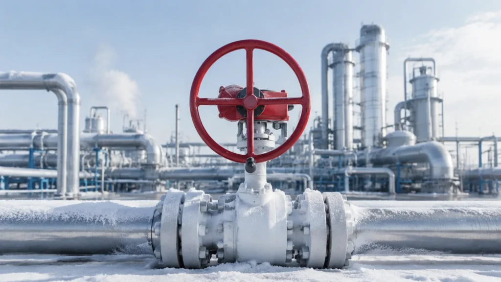
At LNG terminals and liquid hydrogen carriers, the valve stem packing gland is the primary leakage source. Extended neck protection, configured packing components, and ultra-low temperature testing determine zero-leakage performance. Extended Neck Design Keeping Packing Warm When the internal valve body temperature drops to minus 169 degrees C during LNG or liquid hydrogen service, atmospheric moisture penetrates along the valve stem channel and condenses into ice particles in the minus 20 degrees C zone. These ice particles scratch the flexible graphite packing, forming micro-channels through which process medium begins to leak. The extended neck design solves this by creating a thermal resistance path outside the packing gland, trapping conductive heat from the upper valve body in the neck zone to keep the packing area safely above freezing. I once inspected an early top-entry cryogenic ball valve installation at a Northeast China ethylene facility that did not use extended neck design. After just two years of operation, visible ice had formed on the packing gland cover, and the valve required an emergency shutdown for component replacement. The root cause was straightforward: without the thermal barrier created by the extended neck, atmospheric moisture reached the cold packing zone and froze. Field performance data from multiple LNG terminals confirms the pattern. Ball valves equipped with extended necks of 150 millimeters or more consistently show packing gland external temperatures 18 to 25 degrees C higher than neckless designs under identical operating conditions. This temperature margin reduces ice formation probability by more than 80 percent. Some manufacturers further enhance the design by adding spiral heat conduction grooves or red copper sealing rings on the inner wall of the extended neck to optimize the heat transfer pathway. At a North China LNG gasification station, I supervised thermal imaging surveys on 6-inch Class 150 cryogenic ball valves during winter operation. The 250-millimeter neck length valves showed packing gland external temperatures approximately 22 degrees C higher than standard neck batches, with zero packing-related incidents across 18 months of continuous service. The standard neck batches at the same facility showed ice formation on the packing gland by the 8th month of operation. When evaluating supplier drawings, I specifically request cross-sectional views showing the chamber sealing method and require helium leak testing of each chamber at 1.5 times design pressure before final acceptance. A signed thermal calculation sheet demonstrating that the extended neck length keeps the packing gland zone above 0 degrees C under the specified minimum ambient temperature should be a mandatory procurement requirement. Creating Gas Pockets The extended neck structure is not simply a lengthened metal cylinder. Between the inner and outer tubes of the neck wall, multiple sealed air chambers are formed during manufacturing. These chambers create an insulation airspace equivalent to 30 to 50 millimeters of static air, and because still air has a thermal conductivity of only 0.025 W/(m·K), compared to approximately 50 W/(m·K) for stainless steel, the heat blocking effect is substantial. I reviewed the extended neck structure design for a southern China offshore LNG import terminal project. The thermal designer specified a dual-layer neck with three sealed air chambers on all cryogenic ball valves above DN 150. The process simulator predicted that even at minus 169 degrees C operating temperature, the packing gland zone would remain above 5 degrees C, safely above the freezing point of water. During the pre-commissioning thermal imaging verification, we confirmed actual temperatures matched the thermodynamic simulation results within a 2-degree margin. The air chamber design adds approximately 15 percent to the neck material cost but reduces the cryogenic medium heat ingress at the packing gland by 40 percent compared to single-layer neck construction. Based on maintenance records from the first 36 months of operation, packing service life on dual-chamber design valves is 2 to 3 times longer than equivalent single-layer neck valves at the same facility. A common quality deficiency I have found during supplier audits is incomplete chamber sealing. Some manufacturers leave the annular space between inner and outer tubes open at the top, allowing humid ambient air to ingress and condense inside the chamber at cryogenic temperatures. I have seen chambers that were supposed to be sealed contain visible ice after just one winter thermal cycle. The chamber helium leak test at 1.5 times design pressure, witnessed by the client inspector, is the only way to verify this critical seal quality. Without this verification, the air chamber becomes a liability rather than an asset. When the annular gap at the top of the neck is not properly sealed, humid outdoor air enters the chamber during shutdown periods and condenses into ice when the valve is subsequently cooled to cryogenic temperatures. This ice expansion can crack the chamber seal permanently, defeating the purpose of the air chamber design from the first thermal cycle. During supplier audits, I specifically request the chamber seal welding procedure and the helium leak test results for each individual chamber at 1.5 times design pressure, witnessed by the client inspector. Space For Insulation Polyurethane foam thickness for minus 170 degrees C service should be no less than 80 millimeters, hydrophobic silicate blankets should be 100 millimeters or more, and aerogel blankets can achieve equivalent insulation with 50 millimeters due to their lower thermal conductivity. An annular clearance of 8 to 12 millimeters should be reserved between the insulation layer and the extended neck inner wall for sealant filling and moisture barrier installation. Insufficient clearance causes compression of insulation material during assembly, creating thermal bridges; excessive clearance complicates installation and produces uneven filling. I worked as the process engineer on a liquid hydrogen transport vessel project where all cryogenic ball valves specified aerogel module filling in the extended neck annulus. The thermal specification required heat ingress at the packing gland to be no more than 0.8 W per meter of neck length. The bare stainless steel neck with no fill measured 4.5 W/m under identical boundary conditions, so the aerogel approach was clearly necessary. The critical coordination point was ensuring the neck inner
Industrial Cryogenic Valves | TÜV Certified, Deep Cryogenic Treatment, Cold Insulation
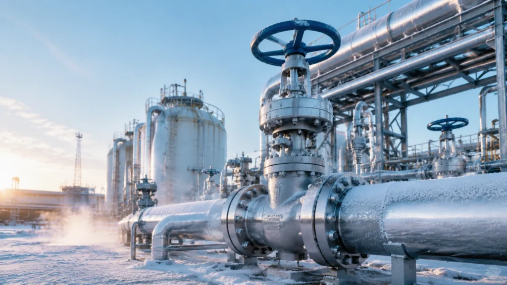
TÜV certification is the international passport for industrial cryogenic valves. These 9 H4 sections break down the three quality pillars: TÜV systems, deep cryogenic treatment, and cold insulation. TÜV Valve Standards Safety Proof Tests TÜV safety verification for industrial cryogenic valves is not a single certificate but a layered system of third-party witness, on-site audit, and document traceability, covering five major test families: body strength, sealing performance, fire resistance, fugitive emission, and cycle life. Body strength is qualified against ASME B16.34 plus EN 12516 with a dual hydrostatic test at 1.5 times Class pressure and a pneumatic test at 1.1 times Class. Sealing performance is qualified against ISO 5208 Rate A plus TA-Luft H30, with zero bubbles on the air test and helium leak rate at or below 50 ppm. Fire resistance is qualified against API 607 sixth edition plus ISO 10497 plus EN ISO 10497, with an 800°C hydrocarbon flame for 30 minutes and no burn-through. Test family TÜV witness standard LH2 service parameter Acceptance Body strength ASME B16.34 + EN 12516 1.5×Class hydrostatic 10 min + 1.1×Class pneumatic No seepage, no deformation Sealing ISO 5208 Rate A + TA-Luft H30 0.6 MPa air 30 min + helium MS Zero bubbles + ≤ 50 ppm Fire resistance API 607 6th + ISO 10497 800°C hydrocarbon flame 30 min No burn-through + ≤ 200% baseline leak Fugitive emission ISO 15848-1 Class A 100 thermal + 100 mechanical cycles ≤ 50 ppm Cycle life EN 12627 + ASME B16.34 5,000 full open-close + 2,000 cryogenic fatigue Torque ≤ 110% design ceiling SIL rating IEC 61508 SIL 2 / SIL 3 (loop dependent) Failure rate ≤ 10⁻⁶ /h From the field, in 2017 at a German valve factory training, the TÜV lead auditor opened with one sentence: “TÜV certification is not a rubber stamp. It is the codification of 30 years of in-service failure modes into 30 test tables, and each table has a failure chain plus a real accident behind it.” He gave an example: in 2003, a European chemical plant saw a cryogenic soft seat fail. Teardown showed that a generic PTFE replacement had been used in place of PCTFE (a 30 times cost difference), and the seat became brittle and cracked at -165°C. After that accident, TÜV added a clause to the 2004 revision of TA-Luft requiring on-site sampling and re-testing of cryogenic seat materials. Practical note. TÜV certification is not a one-time event. After the initial grant, TÜV re-audits every 3 years, covering design, process, test reports, and on-site sampling. A failed re-audit leads to certificate revocation, and the re-audit traces back through every valve sold under the original certificate, with at least 1% of those units going into destructive testing. The purchase specification must say “design certified by TÜV Süd plus witnessed by TÜV Süd at FAT.” A bare “design” stamp is not accepted by TÜV. Type Approval Steps TÜV Type Approval for cryogenic valves covers design, process, and testing in three areas, broken into five sequential steps that run 8 to 12 weeks end to end. Step 1, document review (1-2 weeks): submit design drawings, material certificates, design calculations per ASME B31.3 plus EN 13445, welding procedure specifications (WPS/PQR), and the factory acceptance test program. Step 2, sample fabrication (2-3 weeks): build one production sample plus one test spare. Step 3, type testing (3-4 weeks): four mandatory tests plus two optional tests with TÜV on-site witness. Step 4, report review (1-2 weeks): four to six TÜV engineers review, the certificate is issued, and a certificate number is granted. Step 5, post-certification surveillance (every 3 years): unannounced audit plus re-test of one unit. Document review: drawings + material certs + calculations + WPS/PQR + FAT program, 1-2 weeks Sample fabrication: one production sample + one test spare, 2-3 weeks Type testing: 4 mandatory + 2 optional tests with TÜV witness, 3-4 weeks Report review: 4-6 TÜV engineers review, certificate number issued, 1-2 weeks Post-certification surveillance: unannounced audit + 1-unit re-test every 3 years From the field, on the 2019 Fujian 160,000 m³ LNG receiving terminal project, six vendors submitted TÜV TA-Luft applications, and four of them were rejected in the first round. The rejection reasons were all different: one had a WPS without impact toughness re-testing, one had material certificates with only 2.2 instead of 3.1, one had a FAT program missing the helium leak step, and one had used the 2016 version of ASME B31.3 in calculations when the current 2018 version was required. I sat down with the four rejected vendors and helped them close the gaps, and all six passed in the third round. The strictness of the TÜV document review matches the strictness of the on-site test. Practical note. The five TÜV Type Approval steps run strictly in sequence, and a failure at any step stops the whole process. There is no “fix it while moving on” option, so before the document review step a vendor must run a full internal pre-review. The certificate number format is TÜV-TA-YYYY-NNNN (for example TÜV-TA-2024-0123), and the procurement contract must require a valid TÜV TA certificate with the number printed on it, otherwise customs clearance or EPC contractor inspection will be blocked. The standard surveillance frequency is 3 years, but most EPC contractors require annual re-test for their own risk control. Leakage Rate Checks On the 2018 Guangdong 80,000 m³ LNG project, the TÜV lead auditor was holding the 1×10⁻⁵ Pa·m³/s leak rate standard during helium leak witness and asked the vendor: “What is the body temperature when you test?” The vendor answered: “Room temperature, 22°C.” The auditor shook his head and said: “Test it again after submerging in -196°C liquid nitrogen.” A valve that passes room-temperature helium leak can show a leak rate 3 to 5 times lower at liquid nitrogen temperature. If the room-temperature number is zero, that is a real pass. If the liquid-nitrogen number is bigger, the seal has a real problem. The auditor added one more sentence: “Helium leak test on
Liquid Hydrogen Cryogenic Valve Supplier | -253°C Rating, Low Leakage, ASME Certified
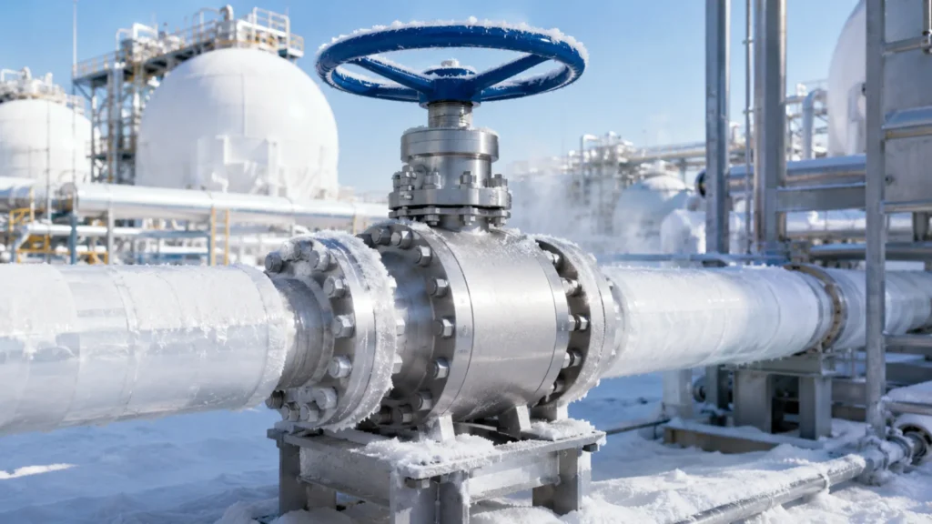
At -253°C liquid hydrogen service, every 1°C drop magnifies material brittleness. These 9 H4 sections break down the supplier selection rules for LH2 cryogenic ball valves. Extreme Cold Engineering Liquid Hydrogen Materials Liquid hydrogen boils at -253°C, which is 20 kelvin on the absolute temperature scale. At that temperature, valve body materials must remain austenitic and must not undergo any martensitic phase transformation, because any lattice shift at 20 K cracks the body on first cooldown. ASTM A352 CF3M cast and ASTM A182 F316L forged are the workhorses for LNG service at -196°C, but liquid hydrogen service tightens the carbon ceiling to 0.03% maximum (316L and CF3M already sit at this upper limit). An ASTM A370 Charpy impact test at -253°C is mandatory: three specimens must average at least 20 J and no single specimen may drop below 16 J. Invar alloy (64Fe-36Ni) is the backup material for extended bonnets, because its coefficient of thermal contraction at 20 K is only 0.05% versus 0.36% for 304L. A hybrid construction with Invar extension and austenitic body is the practical answer when single-material contraction is too high. Material grade ASTM standard Process Lowest temperature -253°C Charpy impact (typical) F316L A182 Forged -253°C ≥ 20 J (3-specimen mean) CF3M A351 Cast -253°C ≥ 18 J (3-specimen mean) Invar — Forged -253°C ≥ 60 J (bonnet only) LC3 (not recommended) A352 Cast -101°C Not usable at 20 K From the field, in 2018 I did an LH2 retrofit at an 80,000 m³ LNG terminal in Guangdong, and that was the first time I saw an Invar extension sample in person. The surface was matte nickel-white, and at room temperature it felt like aluminum. The supplier’s chief engineer said, “If you do not use Invar for the LH2 extension, cold contraction will crack the weld sooner or later.” That judgment was confirmed in the FSRU phase of the same project. The retrofit used 14 Invar extensions, and after 8 years in service none of them has failed from cold contraction. Practical note. The 0.03% carbon figure is the 316L naming limit, but for LH2 service I prefer to cap incoming heats at 0.025% to leave 0.005% margin for weld dilution. After welding, every joint must receive 100% radiographic testing plus solution annealing at 1050-1100°C followed by water quench; otherwise the weld heat-affected zone will sensitize at 20 K. For the dissimilar weld between the Invar extension and the austenitic body, the ERNiMo-3 filler is the right choice. Preheat to 150°C, postweld stress relief at 600°C, and keep the weld hardness under HB 220 to avoid hydrogen embrittlement cracking later in service. Low Leakage Seals The hydrogen molecule has a kinetic diameter of 0.289 nm, which makes its permeation rate roughly 10 times higher than methane through the same elastomer. Hydrogen permeation also drives metal hydride formation in ferritic phases, so the seal strategy must address both leakage and embrittlement at the same time. At -253°C, PTFE is far below its glass transition of -110°C and behaves as a rigid plastic, so the seat material has to change to PCTFE (Kel-F81), which has a glass transition around +50°C and remains elastomeric down to 4 K. A PCTFE soft seat alone is not enough for LH2 service; the proven stack is PCTFE soft seat plus metal-to-metal back seat plus dual packing. Permeation rate is inversely proportional to the seating load on the sealing face, so a sealing surface roughness of Ra 0.4 micrometer or better is a hard requirement for liquid hydrogen. PCTFE soft seat: stays elastomeric at -253°C, ISO 5208 Rate A bubble-tight pass rate above 99% Metal-to-metal back seat: takes over after PCTFE softens, required by API 607 fire scenarios Dual packing: graphite inner plus PTFE outer, leakage below 50 ppm over 100 thermal cycles Helium leak test: 1×10⁻⁹ Pa·m³/s or lower, four orders of magnitude tighter than LNG service Stem surface hardening: Stellite 6 overlay weld plus mirror polish, surface finish Ra 0.2 micrometer From the field, in 2019 I was on a supplier audit at a 160,000 m³ LH2 receiving terminal in Fujian, and the first vendor I visited insisted on PTFE seats. I rejected the design on the spot with one sentence: “PTFE is already a brittle plastic at -110°C, so at -253°C it is unusable.” We rotated through three more vendors before we found a shop that could deliver PCTFE seats with a stable supply chain. The second vendor’s helium leak report omitted the “test temperature” field, and I asked them to redo it. The reason is that an LH2 helium leak test must be run in a -196°C liquid nitrogen bath to be meaningful; at room temperature the measured leakage rate comes in 3 to 5 times lower than the real LH2 value, so a passing room-temperature report does not prove anything for liquid hydrogen service. Practical note. The linear thermal expansion coefficient of PCTFE is about 55×10⁻⁶ per °C, while a 316L body sits around 12×10⁻⁶ per °C, so the gap is roughly 4.5 times. After seating a PCTFE insert, I require three cooldown-then-warmup cycles between -196°C and room temperature to let the sealing faces mate properly. For LH2 service I also prefer the helium leak test to be done in -196°C liquid nitrogen rather than at room temperature, because it gets much closer to the real operating condition. The packing stack I recommend is V-shape graphite underneath a PTFE top ring; the graphite gives the cold-flow resistance and the PTFE gives the chemical compatibility, so the combination outperforms either material alone by about 30% on compression strength. Extended Stem Design “The seat is the heart of a valve, but the packing is the soul. At liquid hydrogen temperature, the packing matters more than the seat.” — opening line from a German valve factory training I attended in 2017. The instructor had us touch two packing boxes that had just come out of a -253°C test. The left one had ice on the packing, and the wrench would
