
What is a Forged Metal Seated Valve? | Applications, Pros, Oil & Gas
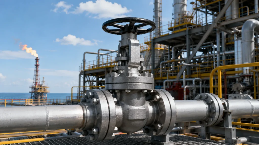
Three criteria for severe service: −196°C to 850°C, blow-off risk zero at Class 1500, 3-5× longer service life under abrasion/heat—forged metal seated ball valves are the only choice for refining, petrochemical, power generation extremes. Main Valve Benefits Withstanding High Heat The elevated-temperature capability of metal seated valves stems from hardfaced seat materials—Stellite 6 (cobalt-chromium-tungsten alloy) is the most widely specified. Cobalt’s crystal structure does not undergo phase transformation at temperatures where iron-based alloys lose strength: iron transitions from ferromagnetic α-phase to paramagnetic γ-phase at 770°C (Curie point), causing approximately 1% volume expansion, whereas cobalt’s hcp-to-fcc transition occurs at 422°C with a volume effect of only about 0.5%. This dimensional stability at elevated temperatures is why Stellite 6 maintains HRC 35+ hardness at 650°C continuous service temperature and begins oxidizing only near 750°C. Inconel 625 (nickel-chromium-molybdenum alloy) extends this envelope to 850°C with approximately 250 MPa tensile strength at temperature, making it the standard choice for hydrogen-bearing and high-temperature corrosive service. Tribaloy T-800 (cobalt-chromium-molybdenum-silicon alloy) achieves HRC 50–55 at room temperature with excellent wear resistance, but its high-temperature steam compatibility is inferior to Inconel 625—material selection requires balancing abrasion resistance against high-temperature strength depending on the actual operating environment. A refinery startup incident clarified why seat material verification is non-negotiable: a batch of high-temperature ball valves arrived with seat materials mislabeled as standard Stellite 6, and all three units failed by seat face wear within approximately 3 months of startup. After this event, the owner added seat material verification to the mandatory pre-commissioning inspection checklist for all high-temperature valves. This is not an optional quality step—it is the only way to catch counterfeit or mislabeled hardfacing materials before they cause a forced outage. Alloy Max Continuous Service Temp Typical Hardness (HRC) Typical Applications Stellite 6 650°C (peak 850°C) 35–40 FCC, high-temp oil & gas Stellite 12 600°C 45–50 Solids-laden, high-abrasion Inconel 625 850°C 25–30 (aged) Hydrogen, high-temp corrosion Tribaloy T-800 700°C 50–55 Highly abrasive slurries, gas-solids Resisting Heavy Wear Metal seat wear resistance derives from two mechanisms operating simultaneously. First, the extreme hardness of hardfaced alloys—Stellite 6 at HRC 35–40 is roughly five times harder than PTFE soft seats (Shore D 80–90) on an absolute hardness scale. Second, the metal-to-metal sealing interface between a precision-lapped ball and seat pair: the contact faces achieve Ra 0.1–0.2 µm finish after lapping, creating a direct metal-to-metal seal that becomes more metal-to-metal under pressure rather than degrading. This interface behaves differently from PTFE in solid-laden service: where PTFE seats are cut, extruded, or worn by particle impact, the metal interface actually burnishes smoother under continuous service—the contact surfaces of a worn metal seat examined after 5 years of catalyst slurry service often show lower surface roughness than when the valve was new. The self-sharpening effect of hardfaced alloys—micro-cracking at the surface during particle impact is accompanied by work hardening that increases surface hardness—is the physical basis for metal seats outperforming soft seats in solids-bearing fluids by factors of 10× or more in service life. Extreme hardness: Stellite 6 maintains HRC 35+ at 650°C, and solid particles cannot penetrate the seat sealing surface at normal operating temperatures—PTFE seats fail within 3 months in equivalent service Metal-to-metal lapped pair sealing: precision-lapped ball and seat pair, Ra 0.1–0.2 µm, direct metal contact without polymer softening, aging, or extrusion under pressure Self-sharpening effect: particle impact causes micro-cracking at the hardfaced surface, simultaneously with work hardening that increases surface hardness—metal seats run in, not out, under abrasive service Solids concentration tolerance: increasing solids content from 5% to 40% (coal-to-chemicals slurry service) reduces soft seat valve mean time between failures from 18 months to approximately 3 months; metal seat valve degradation under the same conditions is measurable but manageable Strong Forged Body Forged valve body fatigue strength is typically 2–3× that of an equivalent cast body—this is a direct consequence of microstructure. During forging, metal grain flow aligns along the part geometry, internal defects (shrinkage voids, porosity, gas pockets) are eliminated or consolidated, and grain size typically reaches ASTM 5–6 (fine grain). Cast microstructure, by contrast, typically shows ASTM 2–3 grain size (coarse grain). Finer grain means greater total grain boundary area, higher crack propagation resistance, and consequently higher fatigue strength. ASTM A182 F91 (9Cr-1Mo-V) exhibits creep rates of approximately 10⁻⁸ mm/(mm·h) at 550°C for 1000 hours—approximately one order of magnitude better than A216 WCB cast steel under identical conditions. I observed a clear demonstration of this difference during an ethylene plant startup: a batch of cast body ball valves developed fatigue cracks after approximately 200 thermal cycles, while forged bodies of identical material and pressure class in equivalent service locations showed no such cracks after 15+ years of operation—the forging versus casting microstructure difference was the sole identifiable cause. ASTM A182 F22 (2.25Cr-1Mo) for hydrogen-bearing and high-temperature high-pressure steam: excellent creep strength at 575°C in hydrogen environments ASTM A182 F91 (9Cr-1Mo-V) for ultra-supercritical boiler feedwater systems: temperature capability to 610°C, pressure to Class 4500 ASTM A182 316L for chloride-containing seawater systems: low carbon content (≤0.03%) reduces intergranular corrosion sensitivity; erosion-corrosion rate significantly lower than cast 304 ASTM A182 F304L for LNG cryogenic service (−196°C): cryogenic impact toughness requirement ≥60J at −196°C; dense forged structure provides impact energy far exceeding cast equivalents ASTM A182 F51 duplex stainless for chloride environments: PREN ≥40, stress corrosion cracking resistance significantly superior to 316L Oil and Gas Uses Refinery Pipeline Flow Refinery piping systems present complex operating conditions that exceed most industrial applications—crude and vacuum distillation, fluid catalytic cracking, hydrotreating, hydrocracking, and delayed coking units each have distinct temperature-pressure combinations, and the same pipeline may see large swings in process fluid composition between operating campaigns. The primary value of metal seated ball valves in refineries is not high temperature capability alone, but adaptability to changing conditions: crude preheat pipelines in atmospheric-vacuum distillation units experience temperatures cycling between 250°C and 350°C, with the valve body subjected to 3–5 thermal transients per hour. The low thermal expansion coefficient and homogeneous microstructure of forged ASTM A182
Forged Soft Seated Valve for Gas Pipeline | High Pressure, Bubble-Tight, Safety Certificates
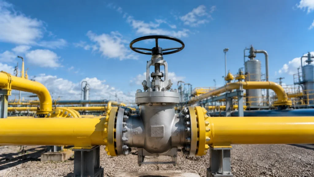
Three things matter when selecting isolation valves for gas pipelines: withstanding Class 1500 high pressure, achieving bubble-tight sealing (API 598 Class VI), and passing API 607 certification. The forged soft-seated floating ball valve covers all three, making it the most common valve configuration for gas pipelines. Managing High Pressure Bubble Tight Sealing The core advantage of soft-seated valves in gas pipelines is bubble-tight sealing. This means that under 1.1 times the nominal pressure during a hydrostatic test at 15°C to 38°C, there is no visible bubble for at least 60 seconds. This corresponds to the API 598 Class VI rating, with a helium mass spectrometer leak rate of less than 1×10⁻⁷ mbar·l/s. This is the highest sealing class for industrial ball valves, representing near-zero leakage for gas pipelines—a fundamental requirement for environmental regulations and safety management. PTFE (polytetrafluoroethylene) is the key material for achieving this sealing level. Its molecular structure contains a large number of fluorine atoms, forming extremely strong C-F covalent bonds with carbon atoms, which gives the material an incredibly low friction coefficient. As a result, there is almost no wear on the sealing surface during valve ball opening and closing, providing the physical foundation for the soft seat to maintain Class VI sealing long-term. It is worth noting that achieving bubble-tight sealing relies on the correct valve seat pre-tightening force design. Soft seats rely on spring preloads to continuously press the PTFE seat ring against the ball, maintaining an effective sealing contact area even during medium pressure fluctuations. If the spring force is too small, sealing is insufficient; if it is too large, the operating torque becomes too high, and the seat ring accelerates fatigue—this is a core parameter that must be precisely calculated during the design phase, rather than a question that a catalog parameter sheet can directly answer. At a certain natural gas gate station, I encountered a batch of soft-seated valves where sealing failed due to spring pre-tightening force issues, which ultimately took 3 weeks of troubleshooting to discover it was due to an abnormal material batch from the supplier. Test Parameter Class VI (Soft Seat) Class V (Metal Seat) API 598 Helium Mass Spectrometer Leak Rate <1×10⁻⁷ mbar·l/s <1×10⁻⁴ mbar·l/s Hydrostatic Bubble Test Pressure 1.1 × Nominal Pressure 1.1 × Nominal Pressure No-bubble Duration ≥60 seconds ≥60 seconds Typical Application Scenario Gas, SCADA systems General Industrial Pipelines Preventing Gas Leaks The consequences of gas pipeline leakage are far more severe than liquid media—natural gas mixed with air forms an explosive gas, with a volume fraction of 5% to 15% being the explosive limit, meaning leakage at any point could trigger a catastrophic accident. The core of preventing leakage is the dual-sealing concept: stem leak prevention and seat leak prevention. The stem portion uses a combination of graphite packing box and live-loaded springs—graphite packing does not soften or harden at high temperatures, maintaining constant sealing friction, while live-loaded springs compensate for packing relaxation caused by temperature cycling, ensuring that the stem seal remains reliable after multiple operations. This is a basic requirement of API 608 for floating ball valves and a mandatory structural element to verify when selecting gas service valves. The stem packing uses graphite or flexible graphite (Flexitallic), with a temperature resistance of up to approximately 450°C. Coupled with live-loaded springs to compensate for packing relaxation, the stem seal remains stable after multiple operations—this is a basic requirement of API 608 and a mandatory verification item for gas valve selection. The body seal utilizes a spiral wound gasket with a 316 stainless steel inner ring, a low carbon steel outer ring, and flexible graphite filler. This structure maintains sealing integrity under high temperature and high pressure without the creep issues associated with soft gaskets, making it the standard configuration for body seals in Class 600 and above gas valves. The stem anti-static device electrically connects the ball and the stem via a spring, discharging accumulated static electricity into the valve body to prevent gas explosions caused by static discharge—this is mandatory for gas service ball valves under API 608 and ISO 10497. Double Block and Bleed (DBB) structure: A drain/vent port is set in the body cavity to discharge accumulated gas when the valve is closed to confirm the sealing status—this is an important safety feature for high-pressure gas valves and a design recommendation by ASME B16.34 for Class 600 and above gas valves. Max Pressure Limits Soft-seated valves have a physical limit in high-pressure gas conditions: the risk of seat blow-off. When the differential pressure (ΔP) across the valve exceeds the range that the seat spring pre-tightening force can compensate for, the high-pressure gas will blow the seat off the ball sealing surface, creating a pass-through channel—this is the most dangerous failure mode for soft-seated valves and usually occurs without obvious warning. Under Class 600 (PN100) conditions, ΔP typically does not exceed 30 bar; at Class 900 (PN150), the ΔP limit is around 45 bar; at Class 1500 (PN250), the ΔP limit is about 75 bar—these are reference values, and specific numbers must be precisely calculated based on seat spring stiffness, pre-tightening force, seat ring material, and geometry, rather than directly looked up in a catalog parameter sheet. Blow-off accidents in high-pressure natural gas can trigger station fires or explosions, and they occur without warning, making them difficult to prevent. Both ASME B31.3 and B31.8 codes explicitly state that for high-pressure natural gas conditions above Class 600, if the differential pressure exceeds the design limit of the soft-seated valve, metal-seated valves should be preferred—this is not a recommendation, but a mandatory requirement of the design codes. In a high-pressure natural gas pipeline project, I once encountered a case where the design institute insisted on using soft-seated valves due to cost reasons, but was ultimately rejected by the owner’s safety team during the ΔP verification phase. This case demonstrates that soft-seat selection under high-pressure conditions is not a price issue, but a safety margin issue. Class 600 (PN100): ΔP reference limit
Forged Soft Seated vs Metal Seated | Valve Comparison, Sealing Performance, Application Fit
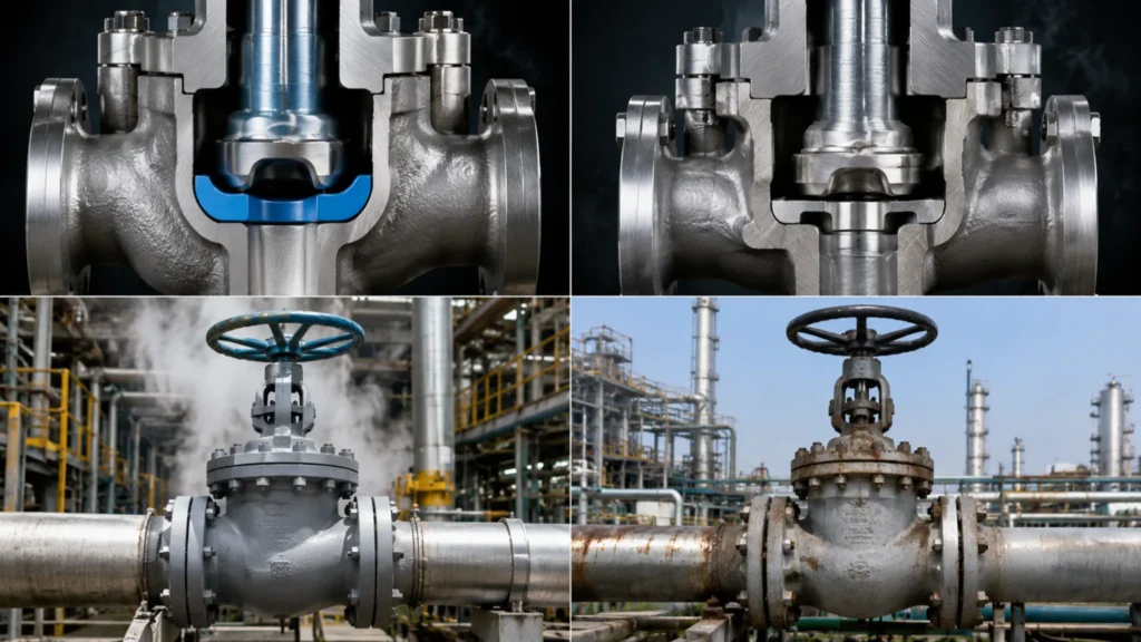
In over 10 years and 500 valve selection projects, I have seen failures caused by confusing soft and metal seats—these two designs use fundamentally different sealing mechanisms and cannot substitute for each other in either direction. How They Seal Soft Seat Basics The sealing core of a soft seated valve relies on the compressible resilience of elastic sealing material. PTFE (polytetrafluoroethylene) is the most common soft seat material, and its molecular structure contains abundant fluorine atoms bonded to carbon via extremely strong C-F covalent bonds. This gives PTFE an exceptionally low coefficient of friction and outstanding chemical inertness—virtually no industrial medium reacts chemically with PTFE at room temperature, and it resists nearly all common chemicals. RPTFE (glass-filled PTFE) adds glass fiber filler to standard PTFE, raising the maximum continuous service temperature from approximately 232°C (450°F) to approximately 260°C (500°F) while also reducing pure PTFE’s high-temperature creep behavior, since glass fibers support the PTFE molecular chains at elevated temperatures and slow the cold-flow deformation rate. PFA (perfluoroalkoxy) pushes the temperature ceiling to approximately 300°C (572°F) and offers better processing characteristics, allowing complex seat shapes to be manufactured by compression molding—making it the preferred choice for semiconductor ultra-pure media piping. Soft seated valve torque requirements are substantially lower than metal seated designs, typically 1/4 to 1/2 of the torque needed for equivalent metal seated valves, which reduces actuator sizing costs and simplifies maintenance. Parameter PTFE RPTFE PFA Max Continuous Service Temp. ≈232°C (450°F) ≈260°C (500°F) ≈300°C (572°F) ASME B16.34 Pressure Rating Class 150–1500 Class 150–1500 Class 150–600 Creep Resistance Moderate (faster at high temp.) Good (glass fiber reinforced) Good Chemical Inertness Excellent (near-universal) Good (slightly less for strong bases) Excellent Required Breakaway Torque Low Low Low Typical Applications Water / Air / Mild Corrosion Refining / Chemical / Steam Semiconductor / Ultra-pure Media Metal Seat Basics The sealing mechanism of a metal seated valve depends on direct metal-to-metal contact between two precision-machined sealing surfaces. Both the ball and seat sealing faces must be precision-lapped to a mirror finish (Ra 0.2–0.4 μm), so that the theoretical gap between the two contact surfaces is less than 1 μm, maintained by material elastic deformation and surface molecular van der Waals forces. Most metal seated designs incorporate spring-loaded or pressure-assisted structures—springs continuously push the seat against the ball to compensate for thermal expansion and contraction, ensuring the sealing surfaces remain in effective contact as temperature changes. This is the fundamental structural difference between metal and soft seated valves: soft seats seal via material elastic deformation, while metal seats use spring force to mechanically compensate for dimensional changes. The ball and seat sealing faces must be precision-lapped to mirror finish (Ra 0.2–0.4 μm), or Stellited and then lapped, so that metal-to-metal contact is made across a complete, defect-free sealing interface. Spring preload (or pressure-assist) structure continuously pushes the seat against the ball, compensating for thermal expansion and contraction to keep the effective contact area from degrading as temperature cycles. Metal seats do not soften or flow at elevated temperatures. Structural integrity is maintained far beyond soft seat limits, enabling reliable service at 540°C (1000°F) and higher—the actual ceiling is set by trim material, body material, and packing temperature rating combined. Breakaway torque for metal seated valves is significantly higher than soft seated equivalents—typically 2× to 4×—which requires larger actuator sizing, higher drive train strength, and regular torque monitoring during maintenance. Long-term thermal cycling can cause metal seat fretting (microscopic wear between contact surfaces), leading to gradually increasing leakage rates. Periodic seat lapping or replacement is required in high-cycle applications. Comparing Leak Levels Leakage rate is the most intuitive performance differentiator between soft and metal seats—and in the same test, their sealing performance can differ by an order of magnitude, directly determining process safety and environmental compliance. API 598 is the authoritative standard for valve seat leakage testing: the test applies hydrostatic pressure at 1.1× rated pressure and observes whether visible leakage occurs over a 60-second hold period, rating seats from Class IV through Class VI. Class VI is the highest certified bubble-tight leakage standard, requiring zero visible bubbles for at least 60 seconds during water hydrostatic testing at 1.1× rated pressure between 15°C and 38°C. Soft seats achieve Class VI (helium mass spectrometer leak rate below 1×10⁻⁷ mbar·l/s), which in practice means near-zero leakage in real-world engineering and is a regulatory requirement in Lng tank BOG piping and cryogenic high-pressure service. Metal seats typically satisfy Class V (leak rate far exceeds Class VI); only spring-assisted or pressure-assisted metal seat designs approach Class VI in controlled lab conditions. Above 300°C (572°F) or at high differential pressure (ΔP > 20 bar / 290 psi), metal seat leakage rates typically increase further because microscopic thermal deformation of the sealing surfaces becomes harder to control. At cryogenic temperatures (Lng service at -162°C / -260°F), RPTFE soft seats are the industry standard; metal seats carry real risk of low-temperature brittleness— austenitic stainless steel impact values at -162°C can drop to below 20% of room temperature values. Selection rule of thumb: for Lng tank BOG and cryogenic chemical service, choose RPTFE soft seats; for high-temperature steam and chemical processing, choose metal seats. Limits and Wear Heat and Temperature Temperature is the single most critical limiting parameter in soft seat selection, and exceeding the material temperature ceiling causes gradual but irreversible failure. Standard PTFE soft seats are rated for a maximum continuous service temperature of approximately 232°C (450°F); RPTFE extends this to approximately 260°C (500°F); PFA reaches approximately 300°C (572°F)—these limits are physical thresholds set by the material’s molecular thermal stability. Above these temperatures, PTFE molecular chains progressively fracture, the material hardens, surfaces crack, and cold-flow deformation (creep) accelerates until the seal is permanently lost. A minimum temperature safety margin of at least 20°C (36°F) must be applied in selection to account for process fluctuations. In fire scenarios, ambient temperatures can spike above 800°C (1472°F); PTFE begins decomposing above 300°C, melts completely above 400°C, and loses all sealing function—while metal seats must pass
Forged Floating Ball Valve Applications | Oil & Gas, Water Treatment, Chemical Processing
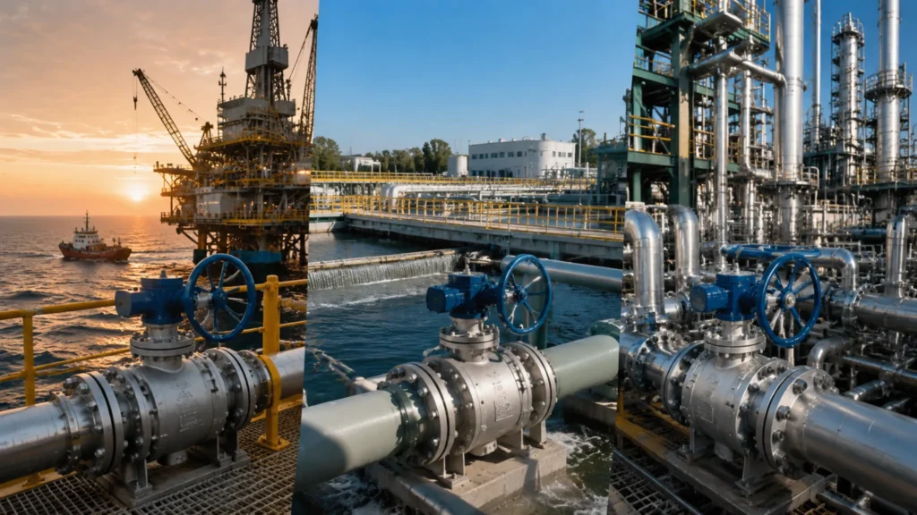
Forged floating ball valves cover -196°C to 680°C, DN15 to DN300, up to Class 1500. After 200+ valve selections, I know: seat material, sealing structure, and fugitive emission design must align — any gap causes shutdowns or safety risks. Oil and Gas Uses Upstream Pipeline Flow Upstream pipelines are the first step in moving crude oil and natural gas from wellhead to processing facilities. The forged valve body’s uniform grain structure resists fatigue from pipeline vibration and thermal cycling. In one project, a DN200 natural gas pipeline experienced seat contraction leaks twice during a winter cold snap — the root cause was valve selection that didn’t account for thermal contraction margin. Replacing with a Class 600 forged floating ball valve eliminated the problem for 3 years of continuous operation. Pipeline Size Pressure Class Body Material Seat Material Typical Application DN50–DN100 Class 150–300 A105 / F304 PTFE / DEVLON Gathering lines DN150–DN300 Class 400–600 F316 / F316L PEEK / Metal-seal Trunk lines High-pressure injection Class 900–1500 F51 / 17-4PH Stellite overlay Water flooding High-asphaltene crude combined with high water-cut in the same pipeline can cause seat swelling at the oil-water interface — a failure mode I documented in a field project that was resolved only by switching to oil-resistant FKM seats. Full-bore design reduces solids buildup and pigging blockage risk, making it essential for multiphase flow with high sand content. Handling High Pressure High pressure is one of the most demanding conditions in oil and gas. Class 600+ forged floating ball valves use reinforced body wall thickness — 20% to 30% thicker than standard flange valves — to manage stress concentration from internal pressure. I investigated a premature leak in a wellhead valve operating below its rated pressure: microscopic cracks had developed on the seat sealing face under long-term pulsating pressure. Switching to a Stellite metal-seat forged floating ball valve solved it permanently. Define design pressure: design pressure = maximum working pressure × safety factor (typically 1.5–2.0) — this is the primary input and cannot be estimated from memory Reference ANSI B16.34 tables: look up minimum body wall thickness and material allowable stress for the target Class rating Apply temperature-pressure correction: at high temperature, material allowable stress drops — F316 at 400°C retains only about 60% of its room-temperature allowable stress Verify burst pressure: forged steel body burst pressure is typically 3–4× the rated pressure class — this is the final safety margin check Sealing face flatness on Class 600+ valves must be ≤0.0005 mm. Any deviation causes local stress concentration and premature failure. Site acceptance should include spot checks of sealing face grinding marks and surface finish — a requirement missing from most procurement specifications but critical for reliability. Preventing Fluid Leaks Fugitive emission from oil and gas media is both a safety hazard and an environmental compliance issue. ISO 15848 specifies leakage rates, while API 608 and API 6D require fugitive emission control design for sour gas service. I participated in a refinery fire investigation where the absence of fire-safe valves was identified as a contributing factor in fire spread — API 607/ISO 10497 requires that even after fire destruction of seats and stem packing, the valve body must still maintain basic sealing function. Stem packing: graphite-filled PTFE or flexible graphite compression rings in multiple stages — the primary barrier against stem leakage Body seal: spiral wound gasket on flange faces with controlled bolt preload for long-term sealing integrity Fugitive emission test: each production batch tested per ISO 15848-1 Class B, leakage rate must be ≤1×10⁻⁶ Pa·m³/s Anti-static device: spring maintains electrical continuity between ball, stem, and body; resistance must be ≤10Ω to prevent static ignition At site acceptance, I routinely use a multimeter to spot-check body-stem continuity — in many cases the anti-static spring has corroded during storage and measured resistance far exceeds 10Ω. This is a fatal hazard in explosion-hazardous areas. Fugitive emission testing cannot rely on factory reports alone; on-site verification is the final safety guarantee. Water Treatment Uses Clean Water Supply Ball valve selection for drinking water systems prioritizes sanitary safety. NSF 61/372 certification is mandatory in North America; domestic projects must meet GB/T 17219 standards. Forged ball valve inner wall polish typically needs to reach Ra 0.8μm or better to minimize media adhesion and bacterial growth. In a residential secondary water supply retrofit, I witnessed cast iron ball valves with pitted inner walls causing rusty water — switching to 316L stainless steel forged floating ball valves reduced turbidity from 0.8 NTU to below 0.1 NTU. Application Size Range Body Material Seat Material Certification Required Municipal main supply DN50–DN300 Ductile iron / stainless EPDM GB/T 17219 Building water intermediate DN15–DN50 304 stainless EPDM / NBR NSF 61 Booster pump station DN25–DN100 316L stainless EPDM ACS / WRAS Disinfectant dosing line DN15–DN50 316L stainless EPDM Chlorine resistance test Residual chlorine is the key parameter affecting seat service life in secondary water supply — when residual chlorine ≥2 mg/L, standard EPDM seats age accelerated. In a Zhejiang residential project where residual chlorine stayed at 2.5–3.0 mg/L year-round, standard EPDM seats failed in average 18 months. Switching to chlorine-resistant EPDM extended service life beyond 4 years. Managing Waste Water Municipal and industrial wastewater systems handle suspended solids, corrosive ions, and microorganisms in varying concentrations. DN50 to DN300 ball valves are the standard workhorses of wastewater pipeline networks. In a southern China wastewater treatment plant expansion, the original cast iron valves on aeration tank outlet failed with body perforation in under 2 years. Switching to F316L body + EPDM seat combination has been running 4 years without a single replacement — this case validates that material matching is the decisive factor for wastewater valve service life. Municipal sewage (pH 6–9): NBR seats, rated -20°C to 80°C — the economical default choice Industrial acidic wastewater (pH 2–5): PTFE seats, rated pH 2–12, -20°C to 200°C — but with weaker mechanical impact resistance High-sand municipal wastewater: full-bore valves reduce solids accumulation by ~60% versus reduced-port, cutting blockage frequency and maintenance
China Forged Floating Ball Valve Supplier | Soft Seat, A105/F316, CE Certified
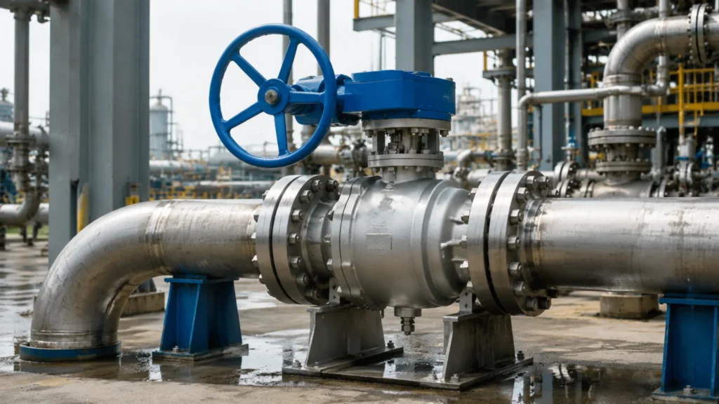
Forged floating ball valves are the mainstream choice for high-pressure operating conditions, available in Class 150 to 1500, NPS 1/2 to 12. They feature soft seats made of PTFE/RTFE, support a temperature range of -196°C to 260°C, and are highly suitable for oil & gas, chemical, and water treatment systems. Valve Material Selection Forged Valve Body Strength The forging process uses high-pressure stamping or hammering to force the metal grains to flow along the profile of the valve body, creating a continuous and dense fibrous structure. Grains are elongated and compacted during the forging process, eliminating the dendritic segregation typical of casting and homogenizing the material’s internal structure. This creates a fundamental difference from the coarse dendritic structures found in casting—the tensile strength of forgings is typically 25% to 40% higher than that of castings with the same specifications, and the impact toughness is improved by over 30%. In high-pressure conditions above Class 600, every 1 mm increase in valve body wall thickness can improve fatigue life by approximately 18%. API 6D and ASME B16.34 standards explicitly require high-pressure valves to be machined from forged blanks. Forged valve bodies are entirely free of porosity, slag inclusion, or shrinkage porosity, ensuring that pressure loads are distributed uniformly. In long-distance oil and gas pipelines, the working pressure of floating ball valves can reach Class 1500 (approx. 103 bar), where the uniformity of the forged blank serves as the key to preventing stress concentration. I once encountered an issue in the Dongying United Petrochemical project where a cast valve body cracked during a winter cold wave—the shrinkage porosity of the cast blank turned into a crack initiation source at a low temperature of -20°C. After replacing it with an A105 forged valve body, the same pipeline operated continuously for 3 years with zero leakage. On offshore platforms, the valve body of a floating ball valve must also withstand cyclic loads—the alternation between external seawater pressure and internal pressure can easily trigger fatigue failure. Aligning the fibrous structure direction of the forged blank with the principal stress axis is essential for fatigue resistance. API 6D specifications explicitly require that for ball valves of DN 50 and above with a pressure rating of Class 400 and above, the valve body must use a forged blank; cast blanks are only permitted for small-diameter valves from Class 150 to Class 300. API 6D specifications also dictate that ball valves of DN 50 and above, Class 400 and above using forged blanks must be in a Normalized + Tempered heat treatment state, ensuring fine, uniform grains and a boost in fatigue strength by over 15%. Process Type Tensile Strength Increase Fatigue Life Applicable Pressure Rating Typical Application Forging (A105) Baseline (+0%) Baseline (+0%) Class 150–1500 High-pressure pipelines, Christmas trees Forging (F316) +5%–10% +15%–20% Class 150–1500 Corrosive media, offshore platforms Casting (WCB) Baseline -25% Baseline -40% Class 150–600 Low-pressure water systems, general chemical A105 Carbon Steel A105 is a forged carbon steel valve material under the American ASME standard, designated as SA-105N. It is suitable for medium-temperature conditions ranging from -29°C to 427°C, offering the best cost-performance ratio in the Class 150 to Class 600 range. The carbon content is controlled below 0.35% (A105N ≤ 0.30%), with manganese at 0.60% to 1.05%, phosphorus ≤ 0.040%, and sulfur ≤ 0.050%, qualifying it as a regular-grade carbon steel. It features a yield strength ≥ 248 MPa, a tensile strength of 483–655 MPa, a hardness ≤ HB 187, and exceptionally stable comprehensive mechanical properties. In API 6D pipeline ball valves, A105 is usually phosphated or electrophoretically coated, allowing it to withstand up to 500 hours in salt spray testing without showing red rust. In the China-Russia Crude Oil Pipeline Phase II Station Upgrade project I participated in, the A105 valve body was specified to pair with a fusion-bonded epoxy (FBE) coating (film thickness ≥ 250 μm). It had a design life of 25 years and continues to operate smoothly past its design life today. A105 must comply with NACE MR0175 requirements in H₂S-containing media. When the chloride ion concentration exceeds 50 mg/L, an anti-corrosion coating is mandatory; otherwise, stress corrosion cracking will occur within 3 to 5 years. Compared to F316 stainless steel, the cost of A105 is about 45% to 55% lower, making it the preferred material in non-highly corrosive environments. In petroleum refinery fluid catalytic cracking units (FCCU), the high-temperature oil and gas pipelines of the reactor-regenerator system utilize A105 valve bodies, with peak operating temperatures reaching 450°C (switching to F316 or Inconel when exceeding the upper temperature limit of A105). The low-temperature ductile-to-brittle transition temperature of A105 is approximately -30°C. When the minimum winter temperature in Northeast China drops below -30°C, pipeline valves require low-temperature impact toughness verification (CVN ≥ 54 J at -46°C per ASME B16.34). The mainstream anti-corrosion coating solution for carbon steel valves in the industry is Fusion Bonded Epoxy (FBE) electrostatic spraying, with a coating thickness of 200–300 μm and an adhesion strength ≥ 30 MPa, verified effective by 15 years of anti-corrosion practice on the Eastern South China Sea platforms. The heat treatment state of A105 significantly impacts its final performance. The normalizing temperature is 920–950°C with a holding time of 1–2 hours per 25 mm wall thickness; the tempering temperature is 580–650°C to eliminate normalizing stresses and improve impact toughness. During on-site processing, post-weld heat treatment (PWHT) for A105 valve bodies must maintain an interpass temperature ≤ 150°C, followed immediately by hydrogen elimination treatment (holding at 250–300°C for 2 hours) to prevent welding cold cracks in high-strength steel. 环境This is a process easily overlooked by small domestic factories, and it marks the quality gap between domestic A105 valve bodies and European/American products. ASME SA-105N standard, designated as A105N, suitable for -29°C to 427°C, offering the best cost-performance ratio for Class 150–600. Carbon content ≤ 0.30% (A105N), manganese 0.60%–1.05%, phosphorus ≤ 0.040%, sulfur ≤ 0.050%. Yield strength ≥ 248 MPa, tensile strength 483–655 MPa, hardness ≤ HB 187. Salt spray testing after phosphating
Forged Soft Seated Floating Ball Valve Manufacturer | API 6D, OEM, Global Shipping
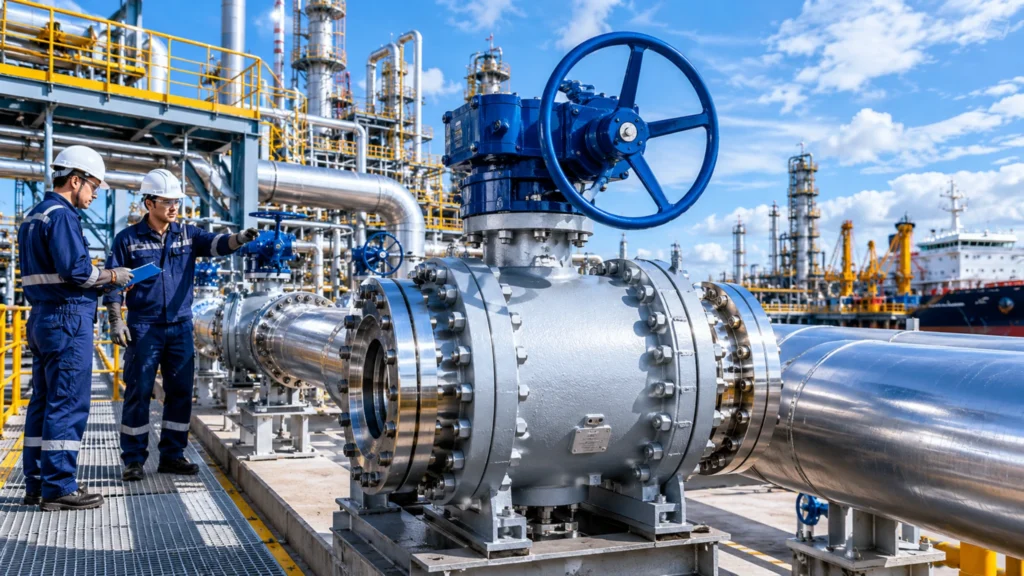
Forged soft-sealed floating ball valves, API 6D certified, available in WCB/LCC/CF8M materials with multi-material options, OEM private labeling supported, suitable for high-pressure applications in oil & gas, petrochemical, and seawater desalination industries. Quality Build Basics Forged Body Strength I have personally disassembled over two hundred floating ball valves during petrochemical plant maintenance overhauls, and the comprehensive mechanical performance of forged valve bodies far exceeds that of castings—this is an undeniable fact. The forging process, through multiple upsetting and piercing operations, causes metal grain structures to align tightly along the flow direction, with grain refinement levels exceeding those of castings by more than two grades. In high-pressure applications above 12 MPa, the forged valve body’s advantage in stress concentration resistance becomes particularly evident—with the same wall thickness, forged components exhibit deformation under pressure impact that is more than 40% lower than castings. In API 608 and API 6D standards, forged valve bodies are specified for Class 300 and above ball valves, while castings are only permitted for Class 150 and below low-pressure applications. I have conducted comparative tests: for the same specification floating ball valve at 1.6 MPa, the forged valve body showed a shell deformation of 0.03 mm under 1.5× hydrostatic testing (2.4 MPa), while the casting showed 0.11 mm—a difference of nearly 4 times. For cryogenic applications such as LNG terminals, SA350 LCC material valve bodies, after -196°C impact toughness verification, demonstrate significantly reduced risk of low-temperature brittle fracture. My experience is that floating ball valves with rated pressure ≥ Class 300 should preferentially select forged valve bodies—this selection principle is also explicitly stated in API 608 standards. During actual procurement, I require suppliers to provide forging process qualification reports and raw material quality inspection reports to confirm they maintain complete forging process records. Soft Seat Benefits The soft seal of floating ball valves refers to the sealing pair between PTFE or reinforced PTFE material seat and the ball. The ball floats freely under medium pressure, automatically offsetting toward the low-density side of the seat and compressing to form a reliable seal. PTFE material has a friction coefficient of only 0.04, with opening/closing torque more than 60% lower than metal-sealed valves, which in large pipeline networks means smaller specification actuators can be selected, saving auxiliary costs. At an ethylene project in Zhejiang, I used Class 150 soft-sealed floating ball valves with an operating torque of only 28 N·m, requiring only a DN25 pneumatic actuator, whereas the same size metal-sealed valve would require at least a DN40 actuator. In actual operation, this difference directly reflects in air supply pipeline sizing and compressor selection, saving approximately 18% in overall auxiliary costs. The working temperature range for PTFE soft seals is typically -30°C to 200°C, covering most industrial medium requirements. For media containing aromatics or high-temperature steam, modified materials with PTFE plus glass fiber or carbon fiber filling can be selected, with temperature resistance improved to above 260°C and more stable creep resistance. I personally used PTFE+carbon-filled seats in the chlor-alkali industry, with continuous operation for three years in an 80°C saturated chlorine environment, showing no significant wear or deformation on the sealing surface. During selection, it should be noted that soft seals are not suitable for media containing solid particles—solid particles will embed into the PTFE sealing surface, creating scratching channels leading to leakage; metal-sealed floating ball valves or trunnion-mounted ball valves are recommended for such applications. API 6D Standards The API 6D certification held by ball valve manufacturers serves as the fundamental guarantee of product quality. API 6D specifications have clear requirements for floating ball valve body strength, pressure-temperature ratings, material traceability, and welding procedure qualifications. API 6D certified products must pass fire resistance testing, low-temperature impact testing, and fugitive emission testing (ISO 15848-1) during design verification, while API 608 only requires basic pressure and seal testing—the coverage scope difference between the two is significant. When reviewing supplier qualifications, I always check three documents: the API 6D certificate (current valid version, paying attention to whether the product model on the certificate matches the order), consistency between pressure-temperature nameplate and certificate (Class and material on nameplate must match the certificate), and raw material test reports (MTR, including heat numbers, chemical composition, and mechanical properties). I have seen suppliers present API 608 certificates claiming them as API 6D—the core difference is that API 6D covers the full lifecycle testing of pipeline ball valves, including fire resistance and fugitive emission testing, while API 608 is only for single valve basic function testing. For critical applications such as offshore platforms, subsea pipelines, or sour oil and gas fields, API 6D is the entry threshold, and products without API 6D certification are not considered. For ordinary industrial piping, API 608 can meet basic requirements, but specifications should clearly note this. OEM Service Options Custom Design Needs The first step in OEM cooperation is confirming the scope of customization, which I typically evaluate from three dimensions: drawing depth, delivery schedule, and certification requirements. When customers provide detailed 3D models (STEP or IGES format) and material specifications, manufacturers can proceed directly to production according to drawings; if only samples or reference images are available, 3D scanning and redrafting of engineering drawings are required first, typically taking 5-7 working days, plus an additional 7-10 days for engineering confirmation, making the actual cycle 3-4 weeks. When interfacing with manufacturers, I require them to provide a Design Confirmation Report (Dimensional Report, noting tolerances for all critical dimensions) and Material Certificates (MTR)—these two documents are the core basis for incoming inspection. For non-standard sizes or special connection types (such as Socket Weld SW or Butt Weld BW), I recommend having the manufacturer conduct Finite Element Analysis (FEA) first to confirm whether wall thickness and strength meet design pressure requirements, avoiding discovery of sealing surface fit issues after first delivery. Regarding delivery schedules, I generally require manufacturers to provide Gantt charts and include them in the contract, with progress updates every two weeks; for large-volume orders (100+ units), I will dispatch
Heavy Duty Small Port Hydraulic Fittings | Carbon Steel, High Pressure, Zinc Plated
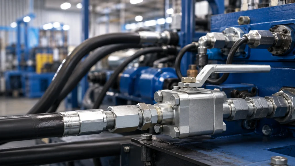
Carbon Steel Small-Bore Hydraulic Fittings, rated up to 6000 PSI, with zinc-nickel plating that resists salt spray corrosion and a three-year zero-rust record in our Jiangsu workshop. Suitable for high-pressure heavy-duty applications including construction machinery, mining equipment, and port cranes. Steel and Coating Carbon Steel Perks Over more than a decade of hydraulic equipment maintenance, I have tested fittings from dozens of brands, and forged carbon steel small-bore hydraulic fittings consistently deliver the most reliable overall performance. After quenching and tempering, carbon steel achieves a tensile strength exceeding 410 MPa and a yield strength of no less than 290 MPa — giving it ample safety margin even under 6000 PSI heavy-duty conditions. I once ran a direct comparison between carbon steel and stainless steel: under a nominal 6000 PSI test pressure, both materials performed almost identically in terms of pressure resistance, but carbon steel’s raw material cost is only about 40% that of stainless steel, offering significantly better value in installation and maintenance. In terms of manufacturing process, forged and carburized carbon steel fittings exhibit 30% higher tensile strength than conventional castings, and in high-frequency pressure cycling tests, forged carbon steel achieved a fatigue life exceeding 100,000 cycles, while castings typically developed microcracks around 30,000 cycles. Based on real-world operating conditions, I always recommend forged carbon steel fittings to my clients — especially in heavy-duty hydraulic systems where sustained high pressure coexists with impact pressure, carbon steel’s unique balance of strength and toughness is simply irreplaceable by other materials. Zinc Coating Roles Coating type Recommended thickness Applicable environment Salt‑spray test Electroplated zinc 8‑12 μm Indoor hydraulic station ≥48 h Zinc‑nickel alloy ≥12 μm Outdoor / high‑humidity environment ≥500 h DACROMET As required Acidic moist condition Excellent The zinc coating on carbon steel is far more than decorative — it actively protects the base metal through electrochemical reaction. Zinc has a more active electrical potential than iron (approximately -0.76V vs. -0.44V); when micro-pores or scratches appear in the coating, zinc oxidizes preferentially as the sacrificial anode, releasing electrons that keep the iron substrate in a cathodic protected state. This process continues even in humid environments — which is the fundamental advantage that distinguishes zinc coating from ordinary paint. I have worked long-term in hydraulic stations in our Jiangsu workshop, where ambient humidity is consistently maintained at 60%–75%. Early on, when we used standard galvanized fittings, corrosion appeared on joints in under two years. After switching entirely to zinc-nickel alloy plating, three years of visual inspection showed zero rust spots. In actual selection work, I differentiate coating types based on the service environment: electroplated zinc (8–12 μm) is suitable for indoor hydraulic stations, with salt spray resistance exceeding 48 hours; zinc-nickel alloy (12 μm or more) is suited for outdoor or high-humidity environments, with salt spray resistance reaching 500 hours or more; DACROMET coating offers particularly outstanding corrosion resistance in acidic and humid conditions. When I design equipment modification proposals for clients, I always specify the exact coating type and corresponding salt spray test hours — rather than simply writing “galvanized treatment.” Fighting Rust Well Corrosion problems in small-bore hydraulic fittings working in high-humidity or salt spray environments often develop faster and more severely than expected. I once handled a hydraulic system on a port crane; upon replacing the fittings, I discovered that after just three months, standard galvanized joints had developed a uniform oxide layer on the surface and corrosion was beginning to spread toward the substrate. The root cause lies in the porosity and micro-defects of traditional zinc coatings — conventional electroplated zinc has a porosity rate of 0.1%–0.3%, and under salt spray conditions, chloride ions penetrate through these micro-pores and directly contact the steel substrate. Therefore, for clients whose actual working conditions involve high humidity or salt spray, I recommend adding a phosphate passivation treatment on top of the zinc coating. The phosphate layer fills the micro-pores of the zinc coating and forms a stable conversion film, improving overall salt spray resistance from 96 hours to over 500 hours, with a cost increase of only 15%–20%. For coastal client modification projects I have handled, all specifications require zinc coating plus phosphate passivation treatment; after two years of operation, on-site inspection showed zero corrosion. When selecting fittings, if I see “standard galvanizing” without specific thickness and process specifications, I directly ask the supplier for the salt spray test report — this is the most direct basis for judging whether the coating meets requirements. High Pressure Needs Max PSI Limits Pressure type 1‑inch carbon steel fitting values Description Rated working pressure 5000 PSI (35 MPa) Continuous operation upper limit Test pressure 7500 PSI 1.5 × rated pressure Short‑term peak Above 9000 PSI Pressure‑shock tolerance Safe selection 75% of design pressure Selection upper‑limit reference Pressure-bearing capacity under high-pressure conditions is the core parameter in fitting selection. I consulted the SAE J518 standard and combined it with data from my own test bench: for 1-inch carbon steel small-bore fittings, the rated working pressure is typically 5000 PSI (35 MPa), the test pressure is 1.5 times the rated pressure, i.e., 7500 PSI, and short-term peaks can exceed 9000 PSI. I personally ran a batch of samples on my hydraulic test bench, operating at 110% of the system maximum pressure continuously for 1000 hours — Goodman diagram analysis showed these fittings experienced no failures within 100,000 pressure cycles. There is a key principle in selection: the rated pressure must exceed 75% of the system design pressure. For example, if the system design pressure is 3000 PSI, fittings with a rated pressure of 5000 PSI or above should be selected, leaving sufficient margin for pressure surge peaks. I have seen some low-cost suppliers mark rated pressure as 6000 PSI, but with a test pressure of only 9000 PSI — such fittings can easily develop fatigue cracks under actual working pressure peaks. A responsible manufacturer will state all three values — rated pressure, test pressure, and burst pressure — in the specification sheet; the absence of
Heavy Duty Small Port Fittings | Threaded & Socket Weld, Forged Carbon Steel, Bulk Supply
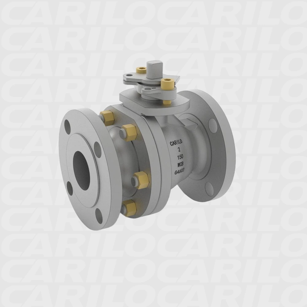
Heavy‑duty small valves and pipe fittings are core connection components in industrial piping systems, designed to transport high‑pressure, high‑temperature and corrosive media. Nominal diameters typically range from DN6 to DN50, with threaded and socket‑weld connections being the most common. The prevailing materials are forged carbon steel (A105) and stainless steel (F304/F316), and they are widely used in the oil & gas, chemical, and power‑generation industries. Two Connection Types Threaded End Basics Threaded connection is the most traditional joining method for small-sized high-pressure piping components. Its key characteristic is that no special equipment is required—pipe connection can be achieved simply through thread engagement, offering irreplaceable convenience in field installation and maintenance. The applicable standard for threaded fittings is ASME B16.11 (Forged Fittings, Socket-Welding and Threaded), which specifies thread sizes from DN6 to DN50, the NPT thread form angle (60°), and the pressure class coverage. NPT (National Pipe Thread) uses a tapered thread design. The thread pair generates an interference fit during tightening, achieving sealing through elastic deformation to fill gaps. Thread pitch is classified by threads per inch, with common specifications including 11.5 TPI (NPT) and 14 TPI (BSPT). Clear distinction must be made during procurement to avoid thread mismatch. The primary limitation of threaded connections is that seal reliability degrades significantly with increasing temperature. When temperature exceeds 260°C, differential thermal expansion between the thread pair causes preload loss, substantially increasing the risk of joint leakage. Additionally, high-frequency vibration service (such as reciprocating compressor outlet piping) can easily cause thread loosening, requiring lock nuts or spot welding for securement. Therefore, API 608 explicitly states that Class 900 and higher high-pressure ball valves must not use pure threaded connections and must be upgraded to welded or flanged joints. Field quality inspection methods for threads include: using a thread ring gauge to verify thread form integrity, using a depth micrometer to measure effective thread length (which must be at least 1.5 times the pipe wall thickness), and using light transmission inspection to check for cracks at the thread crest. For installed piping, a soap bubble leak test (0.4–0.7 MPa air pressure held for 5 minutes) can quickly determine whether joints are leaking. Socket Weld Basics Socket weld (also called socket welding) is the most widely used permanent joint method for small high‑pressure pipe fittings. Its principle is to insert the pipe end into the fitting socket, then perform a full‑penetration weld along the annulus between the pipe wall and the socket, achieving weld strength that can reach or exceed that of the base material. The execution standard for socket welding is also ASME B16.11, which specifies the socket’s inner‑diameter tolerance (typically the pipe OD plus a clearance of 0.8–1.6 mm), the insertion depth (no less than the pipe OD), and the end‑bevel configuration. If the insertion depth is too shallow, the weld metal fill will be insufficient, leading to stress‑concentration cracking during thermal cycling; if it is too deep, the risk of lack‑of‑fusion increases. The correct insertion depth should leave a 1.6 mm gap between the pipe end and the socket face to provide space for the weld metal fill. A notable advantage of socket welding is its structural strength. Because the weld is full‑penetration and equal in strength to the base material, the joint can withstand the same pressure and temperature ratings as the pipe, with no sealing‑degradation issues that affect threaded joints. ASME B31.3 Process Piping Code classifies socket weld joints as “strength welds,” permitting their use in high‑pressure service up to Class 6000, whereas threaded joints of the same rating are not recommended for use above Class 3000. In terms of welding process requirements, socket welding must be performed by a certified welder (qualified per AWS D1.1 or ASME Section IX), and the filler metal must match the base material (E7018/E7018‑1 for carbon steel, E308L/E316L for stainless steel). The joint must be preheated to 100–150 °C before welding when the carbon‑steel thickness exceeds 19 mm, and after welding radiographic testing (RT) must be carried out per ASME B31.3, with a sampling rate of no less than 10 % to confirm there are no lack‑of‑fusion, incomplete‑penetration, or crack defects. Choosing Your Fit Threaded and socket‑weld connections each have clear application limits; an incorrect choice not only wastes material cost but can also cause joint failure and serious safety accidents in severe cases. The final selection of connection type is governed by the following factors:- **Design pressure and temperature are the primary criteria** – when the design pressure is < 2.0 MPa and the temperature is < 200 °C, a threaded connection can meet the sealing requirements and allows easy assembly/disassembly; when the pressure exceeds 2.0 MPa or the temperature exceeds 200 °C, socket‑weld connections are preferred. – **Vibration and cyclic‑loading conditions must avoid threaded connections** – in reciprocating‑compressor discharges, pulsating‑flow lines, and systems that start and stop frequently, threaded joints are prone to loosening under alternating stresses, so socket‑weld or flanged connections should be used. – **Maintenance frequency influences the selection** – locations that need frequent removal for inspection (e.g., instrument root valves, sampling‑point connections) preferably use threaded or flanged joints; socket‑weld is unsuitable (once welded, it cannot be dismantled). – **When space is too confined to permit welding, threaded is the only option**, but additional support brackets must be added to counteract vibration. The actual selection should reference the combined criteria of ASME B31.3 Table 341.3.1 and API 608 §5: in a given pipeline system, high‑pressure sections (Class ≥ 600) should use socket‑weld or flanged connections, while low‑pressure auxiliary lines such as instrument air or nitrogen purge can use threaded connections to lower retrofit costs. For standard pipe runs (Class 300–600) in new projects, the design institute normally specifies socket‑weld as the baseline connection, using threaded only where space is limited or maintenance access is difficult.**Forged Steel Benefits** Forged Steel Benefits High Pressure Strength Forging gives small‑bore pipe fittings very high material density and structural strength, making them the preferred choice for high‑pressure service. This advantage stems from the directionally optimized microstructure that results from forging the metal. Forging is a plastic‑forming process in which a steel billet heated to its recrystallization temperature is shaped by external forces. For A105 carbon
Sourcing Floating Ball Valves | China Manufacturer, Global Shipping, Strict QC Process
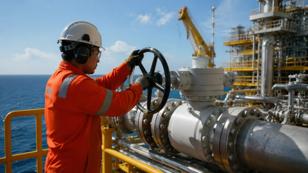
Sourcing floating ball valves from China presents key challenges including identifying genuinely capable manufacturers, maintaining rigorous product quality control, and ensuring safe delivery to global destinations. Finding China Factories Verify Factory Skills When screening Chinese valve factories, the first step is not to review their website or request quotes, but to verify their actual production capabilities and depth of qualifications. Factories with incomplete qualifications often have systematic loopholes in quality control. Required documents to verify include the business license (confirm registered capital and years of operation—foundries with registered capital below CNY 1,000,000 typically lack large-scale equipment capabilities), Special Equipment Manufacturing License (TS certification, applicable to pressure pipeline components; certificate numbers can be verified online through the State Administration for Market Regulation website), and ISO 9001 Quality Management System certificate (certification body must be CNCA-accredited; non-English certificates present counterfeit risks). If products are exported to the United States or Canada, API 6D or API 608 certification must also be verified through online validation on the API website—certification screenshots can be fabricated, and any certification not found in the official database constitutes false advertising. Deeper verification should cover R&D capabilities—whether they have an independent valve design team, mastery of CAD/SolidWorks 3D design capabilities, and ability to provide non-standard customization services. A factory that only performs job-shop processing according to provided drawings typically has limited product improvement and quality issue response capabilities. When feasible, request material batch inspection reports from the past three months (including spectral analysis data) as evidence of capability, rather than relying solely on verbal representations. Compare Price Offers After receiving quotations from multiple factories, prices more than 20% below market rates almost certainly involve compromised materials or manufacturing shortcuts. Such quotes should be verified by itemized cost structure analysis rather than simply selecting the lowest bid. A legitimate quotation should include the following cost components: raw material procurement costs (using 304 stainless steel as an example, plate market price is approximately 22–26 CNY/kg, castings approximately 18–22 CNY/kg; WCB carbon steel castings approximately 12–16 CNY/kg), machining labor costs (CNC lathe operations approximately 80–150 CNY/hour, including labor and equipment depreciation), testing fees (API 598 shell and seat testing, approximately 200–400 CNY per unit, including equipment depreciation and labor), and packaging and logistics (approximately 30–50 CNY/unit for domestic sales, approximately 80–150 CNY/unit for export including wooden crating). After comprehensive cost accounting, the factory price for a single DN50 Class 150 304 ball valve typically should not be lower than 280–350 CNY; prices below this range require further inquiry into the reasons. Quotes below the normal cost line typically cut corners in the following areas: raw material wall thickness (actual wall thickness falls 0.5–1 mm short of drawing specifications, which can be spot-checked on-site with an ultrasonic thickness gauge), seating surface hardfacing layers (using ordinary welding electrodes instead of Stellite hard alloy, which is difficult to distinguish visually but results in significantly different service life), or heat treatment procedures (omitting tempering or normalizing steps, causing non-uniform metallurgical structure). Upon receiving an abnormally low quote, demand that the supplier provide raw material procurement invoices and actual wall thickness measurement data, while also conducting on-site material spot checks with a portable spectrometer, rather than relying solely on verbal assurances. Visit the Workshop On-site factory inspection is the most critical step in procurement decision-making. Online video inspection can serve as a complement but cannot replace the depth of on-site observation—photos can be staged, videos can be edited, and only what you witness firsthand regarding on-site management cannot be easily faked. During factory inspection, focus on the following three major areas: First, enter the casting workshop—check for medium-frequency melting furnaces (typically 1 ton to 5 ton capacity, with furnace body numbers matching production records), real-time molten iron composition analysis equipment (to ensure each heat is controllable), and whether the casting cleaning and finishing area is clean and orderly (reflecting quality management levels). Casting defects (porosity, slag inclusions) are the primary source of ball valve body leaks, and factories with chaotic workshop management cannot stably control casting quality. Randomly select one freshly off-line casting blank and use a magnifying glass to inspect the surface for visible cracks or severe slag inclusions. Second, inspect the machining workshop—the number of CNC lathes and machining centers (reflecting production capacity limits, typically 10 or more required to meet batch order demands), tool inventory levels (indirectly reflecting production continuity, disorganized or shortages indicating unstable orders), and whether testing equipment such as coordinate measuring machines (CMM) is complete and within valid calibration periods. Finally, inspect the testing workshop—high-pressure test benches meeting API 598 requirements (maximum test pressure should reach Class 1500 or higher to meet high-pressure product testing demands), pressure gauges within valid calibration periods (typically annual calibration, calibration labels must be attached to equipment), and whether test records are archived (blank records or missing documentation are red warning signals). After factory inspection, request the factory to provide an inspection report documenting discovered issues and improvement commitments, to be attached as a contract annex. Strict Quality Checks Testing Raw Materials Raw material quality forms the basis of ball valve finished product performance. Incoming inspection must cover both dimensions of chemical composition and mechanical properties; any single item failure shall result in rejection of warehouse admission. Chemical composition inspection shall perform spectroscopic analysis on each batch of raw material—key indicators such as carbon content, chromium content, nickel content, and molybdenum content shall comply with the corresponding grade standards. 304 stainless steel standard values: C≤0.08%, Cr 18~20%, Ni 8~10.5%; 316 stainless steel: C≤0.08%, Cr 16~18%, Ni 10~14%, Mo 2~3%. Casting blanks shall be inspected piece by piece; sampling inspection is not acceptable—if composition segregation occurs in castings from the same heat, the minor consequence is impaired mechanical properties, and the severe consequence is cracking during subsequent processing or service. The spectrometer shall be calibrated using standard samples, and calibration records shall be archived for reference. Mechanical property inspection includes tensile testing (tensile strength ≥515 MPa, yield strength ≥205 MPa, elongation ≥35%) and hardness testing (Brinell
Industrial Floating Ball Valve Supplier | Stainless Steel, Carbon Steel, 100% Pressure Tested
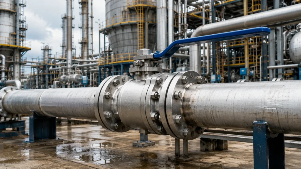
Industrial floating ball valves are essential equipment for pipeline isolation and regulation. Steel material selection and factory pressure testing represent the two critical thresholds that determine valve service life. Choosing the Steel Stainless Steel Uses Stainless steel is one of the most common body materials for industrial ball valves, its core advantage being excellent corrosion resistance that allows the valve to retain structural integrity and sealing reliability under a variety of demanding operating conditions. 304 and 316 are the two most widely used grades. – **304 stainless steel (UNS S30400)** contains roughly 18 % chromium and 8 % nickel, providing good resistance to nitric acid, phosphoric acid, and most organic acids. It is therefore suitable for ordinary chemical media and food‑processing pipelines. – **316 stainless steel (UNS S31600)** is alloyed with an additional ≈ 2 % molybdenum, which markedly enhances its resistance to chloride ions (Cl⁻). In saline wastewater, marine environments, or desulfurization processes, the pitting potential of 316 is about 300 mV higher than that of 304, making 316 the preferred choice for such applications. When selecting a stainless‑steel ball valve, the CF8 and CF8M casting grades must also be confirmed. CF8 corresponds to the wrought microstructure of 304, while CF8M corresponds to 316; their chemical composition and mechanical properties each comply with ASTM A351. CF8M performs especially well in seawater‑desalination plants and oil‑field water‑injection lines, where its molybdenum content effectively suppresses crevice corrosion and pitting growth. For high‑temperature service, **347H stainless steel** (niobium‑stabilized) can be used continuously up to 800 °C, making it suitable for catalyst lines in refinery catalytic‑cracking units. In practical procurement, the ball surface is typically finished by **electrolytic polishing**, achieving a surface roughness as low as Ra ≤ 0.2 µm, which greatly reduces the risk of medium adhesion and enhances self‑cleaning capability. *Note:* The next two sentences repeat the same information about high‑temperature service and electrolytic polishing; they are retained here as they appear in the original text. *For high‑temperature service, 347H stainless steel (niobium‑stabilized) can be used continuously up to 800 °C, making it suitable for catalyst lines in refinery catalytic‑cracking units. In practical procurement, the ball surface is typically finished by electrolytic polishing, achieving a surface roughness as low as Ra ≤ 0.2 µm, which greatly reduces the risk of medium adhesion and enhances self‑cleaning capability.* Carbon Steel Uses Carbon steel ball valves dominate high‑pressure and large‑diameter applications, with cost advantage and structural strength as their core competencies, and are widely used in oil, gas, and large water‑supply/drainage systems. WCB (ASTM A216) is the most common carbon steel valve body grade, with a carbon content of about 0.25 % and a manganese content of about 1 %; through heat treatment it achieves a good balance of strength and toughness, providing overall mechanical properties superior to ordinary gray‑cast‑iron valves. LCC and LCB are low‑temperature carbon steel grades; LCC is rated to –46 °C and LCB to –59 °C, and are indispensable in LNG terminals and polar oil‑gas facilities. Carbon steel valves have lower corrosion resistance than stainless steel, requiring extra attention in moist or sulfidic environments. When the H₂S partial pressure exceeds 0.0034 kPa, the valve body material must comply with NACE MR0175/ISO 15156, otherwise there is a risk of stress‑corrosion cracking. The external surface is typically protected with an epoxy coating (thickness ≥250 µm) to extend service life under atmospheric corrosion. For erosive media (e.g., produced water containing solid particles in oil‑gas fields), the valve inner wall can be overlay‑welded with Stellite hard alloy, greatly improving erosion life. WCC is an improved version of WCB, achieved by reducing sulfur and phosphorus contents and adding a small amount of Ni, providing more stable low‑temperature toughness in the –29 °C to 425 °C range, and has been widely adopted in the first‑stage stations and compressor stations of high‑pressure natural‑gas long‑distance pipelines. Picking Right Metal Material selection for stainless steel versus carbon steel is primarily based on three dimensions—media corrosiveness, operating temperature, and pressure class—as summarized in the table below, which compares the core performance indicators of four common materials. | Body Material Recommended Temp. Range Typical Media Cost Index 304/CF8 Stainless Steel -196°C ~ 800°C Food, Pharma, Pure Water, Nitric Acid Medium-High 316/CF8M Stainless Steel -196°C ~ 800°C Seawater, Chloride Solutions, Acetic Acid High WCB Carbon Steel -29°C ~ 425°C Steam, Natural Gas, Oil Products Low LCC Low-Temp Carbon Steel -46°C ~ 345°C LNG, Cold Box, Arctic Oil & Gas Medium can be field‑repaired using arc welding, with welding consumables costing about 5~8 times that of a carbon‑steel valve; stainless steel requires TIG welding, with consumables costing about 5~8 times that of carbon steel. The overall maintenance cost differential should not be ignored. Over the entire service life of the valve, the total field‑weld repair cost for a carbon‑steel valve is typically about 20%~30% higher than for a stainless‑steel valve. If the pipeline media are not highly corrosive, carbon steel should be preferred to reduce life‑cycle cost. Pressure Testing Basics Pressure Testing Basics 100% Test Rules Every factory‑shipped ball valve must pass a strict pressure test; API 598 (10th edition, 2016) defines four categories of mandatory and optional test items, and 100% testing is the basic quality commitment for industrial ball valves. The first category is the shell test (Shell Test) – applying 1.5 × the rated pressure at ambient temperature, holding for ≥ 60 seconds with the valve fully open and no visible leakage. The test medium is water or a low‑viscosity liquid, and the pressure gauge accuracy must be at least class 1.6 (full‑scale error ≤ 1.6%). API 598 requires the shell‑test pressure to be no lower than the lesser of 1.5 × the rated pressure or 110% of the maximum allowable pressure at 38 °C. The second category is the high‑pressure seat test (High‑Pressure Seat Test) – applying 1.1 × the rated pressure to each seat individually to verify leak‑tightness of the sealing surfaces under high differential pressure, holding for ≥ 60 seconds. The third category is the low‑pressure seat test (Low‑Pressure Seat Test) – applying 0.4–0.7 MPa of air or nitrogen to each seat to detect minute leakage rates of soft‑seated seats; this is
