
| Drawing | Approve before | Do not release when |
|---|---|---|
| GA drawing | End machining, external interface work and final assembly | Dimensions, bore, end details, operator envelope or connection positions remain unclear |
| Cross-section and BOM | Pressure-boundary material purchase and internal component manufacture | Seat action, cavity relief, stem retention, materials or item numbers are unclear |
| Actuator and mounting package | Actuator purchase, bracket fabrication and coupling machining | Minimum output, maximum output, drive-train limit, fail action or mounting details are missing |
| Nameplate and marking drawing | Stamping, engraving and attachment-hole work | Tag, serial number, material, rating, standard or certification marks do not match the order |
| Weld-end or pup-piece drawing | End machining and pressure-containing welding | Actual pipe dimensions, bevel, transition, material, welding or NDE requirements are missing |
| Extension drawing | Stem, bonnet, protective tube and remote-line manufacture | Length, support, sealing, insulation limit or access is not fixed |
| Control diagrams | Tubing, wiring, terminal and panel work | Ports, voltage, signals, fail action or accessory tags conflict with the data sheet |
| Cavity-relief drawing | Relief-device purchase and external piping work | The pressure source, relief route, setting, discharge point or isolation control is unclear |
IOGP S-562 Version 4.0 was published in April 2026 for procurement against API 6D 25th Edition and Addendum 2. API 6D Addendum 3 was issued on March 5, 2025. When both are named in the order, state whether Addendum 3 applies and which document takes priority where the requirements differ.[2]
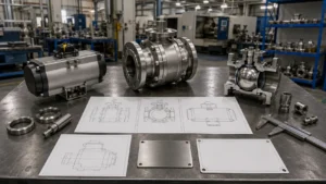
Reject a GA That Does Not Show the Complete Installed Package
The GA must identify the exact valve supplied, including:
- Purchase order and item number
- Valve tag number or tag range
- Manufacturer and valve model
- Drawing number and revision
- Valve size and pressure class
- Applicable design standard and edition
- Body construction
- Full-opening or reduced-opening bore
- Flanged, butt-weld or other end connection
- Lever, gearbox or actuator type
- Fixed operator orientation
- Bare-valve and assembled weights
One GA may cover several tags only when their body design, dimensions, bore, materials, seat arrangement, end connections and operator package are identical. Remove unused options from the production drawing.
Check these dimensions against the valve data sheet and piping layout:
- Face-to-face or end-to-end length
- Valve centreline to operator top
- Overall height, width and length
- Handwheel diameter or lever travel
- Complete actuator and accessory envelope
- Flange dimensions and bolt holes
- Drain, vent and injection-point positions
- Space for removing the actuator or gearbox
- Space for adjusting or replacing stem packing
- Specified dimensional tolerances
ASME B16.10 covers face-to-face and end-to-end dimensions for the valve types within its scope. Use the edition named in the order and check that the vendor drawing matches the selected valve pattern and pressure class.[4]
Illustrative check: An approved face-to-face dimension is 900 mm, but the finished valve measures 904 mm. The 4 mm difference may prevent installation between fixed flanges. Do not accept the valve because the difference “looks small”; compare it with the specified tolerance.
For applicable flanged-end configurations under API 6D Addendum 3, lateral misalignment is limited to 2 mm for NPS 4 and smaller valves and 3 mm for larger valves. These are flange-related limits in the amended clauses, not general tolerances for every GA dimension.[2]
Show the complete operator package, not only the actuator housing. Include:
- Limit-switch box
- Solenoid valve
- Filter regulator
- Pressure gauges
- Boosters and quick-exhaust valves
- Terminal boxes and cable entries
- Local control station
- Pneumatic or hydraulic tubing
- Manual override
Illustrative check: A bare actuator is 620 mm wide. After adding the switch box, solenoid and filter regulator, the complete package reaches 780 mm. The missing 160 mm can place an accessory inside an adjacent pipe or platform.
Where IOGP S-562 applies, the lever length is limited to 610 mm or twice the valve face-to-face or end-to-end length, whichever is less. The handwheel diameter is limited to 800 mm or the valve face-to-face or end-to-end dimension, whichever is less. A 75 mm clearance is required between the outer edge of the lever or handwheel and components within its movement range.[3]
Use Actual Flange and Pipe Dimensions
For flanged valves, the GA or end-detail drawing must state:
- Flange standard and edition
- Pressure class
- Raised-face or ring-type-joint facing
- Facing finish
- Flange outside diameter and thickness
- Bolt-circle diameter
- Bolt-hole quantity and diameter
- Ring groove designation where applicable
For butt-weld valves, use the actual mating pipe dimensions. ASME B16.25 covers butt-welding-end preparation, including bevels and internal shaping of heavy-wall components.[5]
The drawing must state:
- Pipe outside diameter
- Nominal and actual wall thickness
- Pipe schedule
- Corrosion allowance
- Bevel angle
- Root face
- Finished valve-end inside diameter
- Internal transition diameter and length
- Pup-piece material and length
- Corrosion-resistant overlay termination
- Pressure-containing weld location
- Required heat treatment and NDE
Do not release machining from a note that says “ends to suit pipe.” A Schedule 40 pipe and Schedule 80 pipe of the same nominal size have different inside diameters. Heavy-wall pipe, overlay and corrosion allowance can change both the finished bore and the minimum remaining wall.
Approve Piggability from the Smallest Finished Bore
Do not approve a piggable valve from the words “full bore.” Record the smallest finished opening at:
- Upstream valve end
- Upstream seat ring or retainer
- Ball entrance
- Ball-port centre
- Ball exit
- Downstream seat ring or retainer
- Downstream valve end
Compare those dimensions with the exact pig or inspection tool. The checks in how to confirm whether a full-bore ball valve is truly piggable cover pipe Schedule, seat bore, internal steps, weld shape and transition length.
Reject the drawing when it leaves any of these items open:
- Minimum finished bore
- Seat or seat-retainer intrusion
- Weld-end bore step
- Pup-piece alignment
- Gasket inside diameter
- Coating or overlay thickness
- Full-open ball position
- Maximum inward step or offset
- Required transition length
Illustrative check: A rigid tool requires a minimum clear opening of 286 mm, but the smallest finished seat bore is 282 mm. The valve is 4 mm too small even when the pipe and ball port are both nominally 300 mm.
A coating or overlay reduces the bore on both sides. A uniform 1.5 mm layer reduces the finished diameter by 3 mm. Check the maximum finished thickness rather than only the average coating target.
IOGP S-562 requires the specified bore to continue through the complete valve, transition piece and pipe pup when piggability is specified. It also requires snagging areas between the seat and ball to be prevented.[3]
Match Every Cross-Section Item to the BOM
The cross-section and BOM must define one production design. Reject drawings that show alternative seats, seals, materials or body arrangements without identifying the supplied option.
Confirm:
- Floating or trunnion-mounted ball
- Side-entry, top-entry or end-entry body
- Two-piece or three-piece construction
- Bolted or fully welded body
- Soft or metal seats
- Body-joint construction
- Ball and trunnion support
- Seat springs and rear seals
- Stem retention
- Stem packing and bearings
- Drain, vent and injection passages
- Antistatic contacts
- Torque path from operator to ball
A project-specific forged soft-seated trunnion ball valve can use SPE/SPE, DPE/DPE or SPE/DPE seats. The production cross-section must show only the selected arrangement and its pressure direction.
The BOM must give a material specification and grade for:
- Body and end connectors
- Bonnet or cover
- Ball, stem and trunnions
- Seat carriers and inserts
- Body and stem seals
- Bearings and thrust washers
- Springs
- Pressure-boundary bolting
- Drain, vent and injection fittings
- Weld overlay, plating and hardfacing
Do not approve broad terms such as “carbon steel,” “stainless steel,” “PTFE” or “FKM.” The BOM should identify the actual grade or compound needed for purchasing and traceability.
Illustrative check: The cross-section contains 24 numbered parts, but the BOM contains 23 entries. The missing part may be a spring, backup ring or retaining component. Its material and function must be defined before internal materials are released.
For non-metallic seals, check the complete temperature and fluid range rather than only normal operation.
Illustrative check: Normal service is 40°C, but the valve design range is −20°C to 120°C. The seat and O-ring must also withstand startup, shutdown, cleaning and depressurisation conditions across that range.
When IOGP S-562 applies, the elastomer O-ring grade and brand name must be provided. For Class 600 and above, the O-ring section must be qualified for resistance to rapid gas decompression at the maximum allowable working pressure or above.[3]
Read SPE, DPE, DBB and DIB from the Drawing
| Seat arrangement | What the drawing must show | Do not approve until |
|---|---|---|
| SPE/SPE | Each seat seals from the line side and can normally release excess cavity pressure toward a lower-pressure side | The pressure direction and relief path through both seats are clear |
| DPE/DPE | Each seat can seal when pressure acts from either the line or cavity side | A separate cavity-relief method is defined where liquid can be trapped |
| SPE/DPE | The SPE seat provides the planned relief path and the DPE seat provides the second isolation barrier | The position of each seat and the required installation direction are fixed |
IOGP S-562 defines DIB-1 as a valve with two bidirectional seats and DIB-2 as a valve with one unidirectional seat and one bidirectional seat.[3]
Do not accept “DBB” or “DIB” as enough information. Check:
- Which side normally carries pressure
- Which seat is SPE or DPE
- Which seat provides the first barrier
- Which seat provides the second barrier
- Where trapped cavity pressure is released
- Whether a flow or pressure-direction arrow is required
- Whether the planned seat-test directions match the design
If the valve leaks only in one pressure direction, check seat position, valve orientation, travel-stop setting and rear-seat seals. The practical checks are listed in ball valve leakage in one flow direction.
Do Not Release DPE/DPE Without a Cavity-Relief Route
The drawing must answer these questions:
- Can liquid become trapped between the seats?
- Which seat or relief device opens first?
- What pressure difference starts relief?
- Where is the fluid discharged?
- Will the path work if one pipeline side is isolated?
- Can a manual valve accidentally block the relief route?
- Can deposits, ice or high seal friction stop the relief action?
- Does the nameplate or body need a pressure-direction arrow?
API 6D Addendum 3 requires automatic cavity relief where liquid trapping is possible. For temperatures up to 121°C, the cavity-relief pressure must not exceed 33% differential pressure above the valve pressure rating. For gas or multiphase service above 121°C, the manufacturer must determine whether relief is required and state the cavity-relief and higher shell-design pressures.[2]
IOGP S-562 Version 4.0 limits cavity-relief pressure to the lower of 33% of the valve pressure rating or 30 bar. The 30 bar value is part of the permitted relief-pressure limit; it is not an absolute body-cavity pressure limit of 30 bar. Except for DIB-1 valves, S-562 requires internal relief through self-relieving seat rings. A DIB-1 relief system must be submitted for purchaser acceptance when cavity relief is specified.[3]
A closed manual bleed valve does not provide automatic overpressure protection. The pressure sources and relief paths are detailed in why pressure builds inside a closed ball valve.
An integrated DBB compact manifold may combine block and bleed functions in one body, but the sectional drawing must still distinguish the manual bleed passage from the automatic thermal-relief path.
Check Stem Retention and Qualification Coverage
Reject a cross-section that does not show a positive internal stem-retention feature. Packing, gland bolts, the operator bracket or an external retaining part must not be the only protection against stem ejection.
Check:
- Integral stem shoulder or other approved internal retention
- Thrust washer and bearing positions
- Packing stack and gland arrangement
- Stem sealing-surface finish
- Stem injection passage
- Antistatic contact between ball, stem and body
- Stem-to-ball connection
- Clearance from adjacent static metal parts
IOGP S-562 requires stem retention by an integral stem shoulder and does not accept graphite seals as the means of electrical continuity.[3]
For a fire-tested valve, compare the production drawing with the qualified:
- Body construction
- Body-joint arrangement
- Seat concept
- Stem seal
- Graphite backup seals
- Metal secondary sealing features
- Size range
- Pressure-class range
ISO 10497:2022 specifies fire type-testing requirements for valves. The actuator is outside the scope of that valve fire test.[6]
For low-emission qualification, compare the production packing, body joints, test temperature, pressure class and mechanical-cycle range with the certificate. ISO 15848-1:2015 covers classification and type-testing of valves for fugitive emissions.[7]
Do not approve a fire-safe or low-emission statement only because a certificate from the same manufacturer exists. Confirm that the supplied design remains inside the certificate’s qualified range.
Do Not Size the Actuator from One Torque Number
The actuator package should include:
- Complete valve-and-actuator GA
- Valve torque table
- Actuator data sheet
- Actuator sizing calculation
- Gearbox data where applicable
- Bracket drawing
- Coupling drawing
- Drive-train allowable-torque check
- Pneumatic or hydraulic schematic
- Wiring and terminal diagrams
- Accessory list
- Functional test procedure
The valve torque table should identify, where applicable:
- Break-to-open torque
- Running-to-open torque
- End-to-open torque
- Break-to-close torque
- Running-to-close torque
- End-to-close torque
- Maximum required operating torque
- Maximum allowable stem torque
- Allowable torque of the coupling, key, gearbox and ball connection
The calculation basis must state:
- Maximum differential pressure
- Seat material and arrangement
- Process fluid
- Minimum and maximum temperature
- Minimum available air, hydraulic pressure or voltage
- Maximum available supply
- Required opening and closing time
- Emergency duty
- Project sizing margin
The actuator must pass two checks:
- Minimum output must exceed the required valve torque with the specified margin.
- Maximum output must remain below the lowest allowable torque in the drive train.
| Illustrative torque check | Value |
|---|---|
| Maximum required valve torque | 6,000 Nm |
| Example sizing factor | 1.25 |
| Minimum required actuator output | 7,500 Nm |
| Output at minimum supply | 8,100 Nm |
| Output at maximum supply | 11,800 Nm |
| Lowest drive-train limit | 11,000 Nm |
The actuator has a 600 Nm margin at minimum supply, but exceeds the drive-train limit by 800 Nm at maximum supply. Change the actuator or provide an accepted output-limiting method. The factor of 1.25 is an example, not a universal requirement.
Select the margin from the actual duty rather than applying an unexplained percentage. See actuator safety factors for normal, emergency and low-temperature service.
Compare actuator output with the complete drive train, not only the stem. The calculation points are covered in maximum allowable stem torque and actuator limits.
Approve the Bracket, Coupling and Fail Action Together
ISO 5211:2026 specifies attachment and drive-component requirements for part-turn valve actuators.[8] ISO 5640:2024 covers metallic mounting kits where direct mounting is not practical; stacking multiple mounting kits or intermediate supports is outside its scope.[9] ISO 5115:2023 covers part-turn actuated valve assemblies supplied as a package.[10]
The bracket drawing must state:
- Material and thickness
- Valve-side and actuator-side bolt patterns
- Bolt sizes and grades
- Weld details where used
- Corrosion protection
- Assembly orientation
- Design torque and external loads
- Access openings
Reject a bracket that blocks access to the stem packing, gland bolts, injection fittings or body bolting.
The coupling drawing must state:
- Material and heat treatment
- Inside and outside drive shapes
- Key or spline dimensions
- Engagement length
- Machining tolerances
- Retention method
- Assembly-orientation marks
The coupling and mounting arrangement should prevent incorrect 90-degree assembly.
The valve data sheet, actuator drawing and control diagram must state the same final position:
- Fail closed
- Fail open
- Fail in place
- Remain in the last position
Check the full failure sequence:
- The control signal, power, instrument air or hydraulic pressure is lost.
- The solenoid changes or holds its port condition.
- The spring or stored-energy device moves the actuator.
- The valve reaches the required position.
- The limit switch reports the final position.
Illustrative check: The process requires closing within 15 seconds, but the package test records 22 seconds. The valve fails the requirement even when it reaches the closed position. A closing time of 5 seconds may also require a surge check.
The final package test should confirm:
- Opening and closing direction
- Full-open and full-closed travel
- Opening and closing time
- Limit-switch feedback
- Position indication
- Fail action
- Manual override
- Torque-switch settings where applicable
- Agreement with approved tubing and wiring diagrams
Shell, seat and functional tests verify different parts of the package. Match them to the approved ITP and applicable API 6D ball valve testing requirements.
Approve Permanent Marking Before It Is Made
The marking drawing must distinguish body marking from nameplate information.
Check the required:
- Manufacturer name or trademark
- Valve size and pressure class
- Body material
- Valve standard
- Model
- Individual serial number
- Manufacturing date or year
- Purchase order and item number
- Valve tag
- Data-sheet identification
- Pressure-temperature information
- Weld-end wall thickness where required
- Flow or preferred pressure direction
- Quality level where specified
- Supported fire-safe, low-emission and regulatory marks
MSS SP-25 establishes a marking system for new valves and related piping components.[11] ASME B16.34-2025 includes marking requirements for valves within its scope.[12]
Where IOGP S-562 applies:
- The nameplate is 316 austenitic stainless steel.
- Marking is die-stamped or laser engraved.
- US customary and SI units are included.
- Rivet holes are drilled before the body hydrostatic test.
- The plate is attached after coating.
- Multiple plates are used when needed for legibility.
These requirements come from the marking and nameplate clauses of IOGP S-562 Version 4.0.[3]
Use this traceability route:
Valve tag → individual serial number → approved data sheet → material certificates → inspection reports → pressure-test record → release note.
Illustrative check: Twelve valves are supplied under one purchase order. All 12 need individual serial numbers linked to their own test and inspection records. One shared batch serial number does not provide individual valve traceability.
Do not approve a fire-safe, low-emission, sour-service or regulatory mark unless the supplier has supporting records for the supplied design.
Request Extra Drawings Only When the Configuration Needs Them
| Valve feature | Required drawing | Items to fix before release |
|---|---|---|
| Butt-weld ends | Weld-end detail | Pipe OD, wall, bevel, root face, bore transition and remaining wall |
| Pup pieces | Pup-piece and weld drawing | Material, length, weld location, procedure, heat treatment and NDE |
| Buried valve | Stem extension and valve-box arrangement | Length, guides, sealing, operator support and remote connections |
| Cryogenic or insulated valve | Extended bonnet and insulation drawing | Packing position, insulation limit, orientation, support and cold torque |
| External cavity relief | Relief schematic | Connection, setting, tube size, backpressure, discharge and isolation control |
| Automated valve | Pneumatic, hydraulic and electrical diagrams | Ports, wires, terminals, signals, fail action and accessory tags |
| Heavy or uneven package | Lifting drawing | Total weight, centre of gravity, lifting points, sling angles and prohibited points |
A forged cryogenic ball valve needs more than a longer stem. The drawing must keep the packing outside the cold zone and account for insulation, material contraction, support and low-temperature operating torque.
Where IOGP S-562 applies, permanent lifting points are required for valves NPS 8 and above and for valves weighing more than 250 kg. Lifting instructions must not use gearbox lifting points. Valves with a calculated weight above 1,000 kg, excluding packaging, must be weighed; for identical valves above that limit, one valve may be weighed.[3]
Write the Exact Production Activity on the Approval
| Status | Permitted action |
|---|---|
| Accepted | The named production activity may proceed. |
| Accepted with comments | Proceed only when the project procedure allows it and the comments do not affect the released work. |
| Revise and resubmit | Do not proceed with the affected work. |
| For information | No production release is created. |
| Rejected | Do not proceed with the affected work. |
Approval code numbers are not universal. Write the meaning of each code in the vendor document procedure.
Use separate releases for:
- Long-lead materials
- Final valve machining
- Internal component manufacture
- Actuator purchase
- Bracket and coupling fabrication
- Control-package assembly
- Permanent marking
- Shipment
A partial release must state the exact material or equipment released, fixed dimensions, open items, permitted work and responsibility if the design later changes.
Illustrative comment check: A drawing contains 18 comments. Fifteen concern spelling, line weight and document format. One concerns an incorrect seat material. The one technical comment blocks material release even though most comments are editorial.
A drawing approval and an ITP hold point are different. IOGP S-562Q defines a hold point as a stage beyond which work cannot continue without purchaser approval. At a witness point, the manufacturer gives notice, but work may proceed after the agreed notice period when the purchaser does not attend.[13]
Use the drawing schedule for technical approval and the valve inspection and test plan for hold, witness, surveillance and record-review points.
Reapprove Technical Changes
Submit a revised drawing and technical deviation before changing:
- Body construction
- Forged or cast manufacturing route
- Face-to-face or end-to-end dimension
- Bore
- Flange or weld-end geometry
- Pressure-boundary material
- Ball, stem or seat material
- Seal compound
- Seat arrangement
- Cavity-relief method
- Stem size
- Actuator or gearbox model
- Bracket or coupling
- Fail action
- Stroke time
- Nameplate data
The deviation request must state:
- Original requirement
- Proposed change
- Reason for the change
- Effect on dimensions
- Effect on pressure integrity
- Effect on sealing and operation
- Effect on testing and qualification
- Commercial and schedule effect
- Every affected document
Do not hide a deviation inside a new drawing revision. After acceptance, update the GA, cross-section, BOM, data sheet, actuator package, nameplate and final records together.
Purchaser approval does not transfer responsibility for design, strength, materials, manufacturing, testing or drawing accuracy from the manufacturer.
Use One Final Go/No-Go Check
- The document status permits the named production activity.
- The purchase order, data sheet and drawings use the same tag and revision.
- The drawing shows the exact valve configuration without unused options.
- Face-to-face or end-to-end dimensions are correct.
- Flange or weld-end details match the actual piping interface.
- The complete operator and accessory envelope is shown.
- Drain, vent and injection points remain accessible.
- The minimum finished bore meets the flow and pigging requirement.
- Every cross-section item has one matching BOM entry.
- Critical materials have a standard, grade or compound.
- SPE and DPE seat positions are clear.
- Cavity pressure has an automatic relief route where required.
- Stem retention and the complete torque path are shown.
- Fire-safe and low-emission details match the qualification records.
- Valve torque uses the required pressure and temperature conditions.
- Actuator output is sufficient at minimum supply.
- Maximum actuator output remains below the lowest drive-train limit.
- The bracket and coupling can carry the stated torque.
- Fail action and stroke time match the process requirement.
- Control diagrams match the GA and accessory list.
- Nameplate data match the physical valve and quality records.
- Approved deviations appear in every affected document.
- All technical comments have a recorded response.
- The approved revision is available to production and inspection staff.
Finally
Release each activity from the drawing that controls it: materials from the approved cross-section and BOM, final machining from the GA and end details, actuator work from the torque and mounting package, and permanent marking from the nameplate drawing. Stop release when a 4 mm dimensional error blocks installation or pigging, when DPE/DPE seats have no relief route, or when maximum actuator output exceeds the drive-train limit. Every supplied valve needs an individual serial number linked to its material and test records. A later change to dimensions, materials, seats, actuation or marking requires a revised drawing and formal approval before the affected work continues.







