
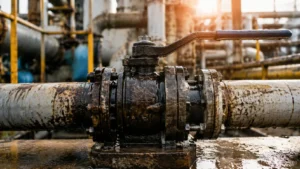
Check the Symptom
The point at which resistance occurs gives the first clue.
| Symptom | Likely cause |
|---|---|
| Hard only when movement starts | Seat adhesion, dried product, tight packing, or high breakaway torque |
| Hard through the full stroke | Seat deformation, heavy deposits, body distortion, stem damage, or bearing damage |
| Hard near the closed position | Debris on the seat, damaged seat, ball misalignment, or incorrect travel stop |
| Hard only under pressure | Differential-pressure loading, trapped cavity pressure, or insufficient actuator torque |
| Hard after shutdown | Dried product, crystals, wax, freezing, corrosion, or seat adhesion |
| Rough or grinding movement | Rust, sand, welding debris, scratched ball, damaged bearing, or metal galling |
| Slow but smooth movement | Low actuator output, restricted air supply, high fluid viscosity, or gearbox friction |
| Stops at the same point every time | Local deposit, damaged ball, deformed seat, or incorrectly set stop |
| Actuator stalls but the valve turns normally after safe separation | Actuator, gearbox, power supply, control accessory, or coupling fault |
| Valve remains tight after the actuator is safely removed | Internal valve resistance, packing friction, corrosion, deposits, or seat damage |
| Easier after depressurization | Pressure loading is contributing to the torque |
| Harder when hot | Seat expansion, pipe movement, cavity pressure, or hot deposits |
| Harder when cold | High viscosity, frozen moisture, wax, crystals, or hardened seals |
Record the conditions while the fault is present:
- Upstream and downstream pressure
- Valve-body temperature
- Opening or closing direction
- Time since the previous cycle
- Time required for a full stroke
- Pneumatic pressure at the actuator while it moves
- Electric actuator current and alarm records
- Recent changes to the fluid, cleaning process, pressure, or shutdown method
Stroke time is a useful maintenance record. For example, if a valve originally completed its stroke in 5 seconds but now requires 8 seconds under the same operating conditions, the stroke time has increased by 60%:
(8 − 5) ÷ 5 × 100% = 60%
A 60% increase does not identify the cause by itself, but it confirms that the valve, actuator, supply system, or process condition has changed.
Check simple external causes first. A bent handle, engaged locking plate, ice around the stem, loose coupling, deformed bracket, incorrect stop, or water-filled gearbox can make a healthy valve appear stuck.
Understand the Torque
Valve torque is the turning force needed to rotate the ball. It is not one fixed value throughout the stroke.
- Breakaway torque starts the valve moving from rest.
- Running torque keeps the ball moving after the first movement.
- Reseating torque is needed as the ball returns to the closed sealing position.
Long idle periods, pressure loading, sticky product, or tight packing often raise breakaway torque. Heavy deposits, seat deformation, body distortion, or damaged bearings can keep running torque high throughout the stroke.
For more detail, see how to read breakaway, running, and reseating torque.
The actual torque depends on valve size, bore, seat material, differential pressure, temperature, packing load, fluid condition, operating frequency, and wear.
ASME B16.34 covers pressure-temperature ratings, materials, dimensions, examination, testing, and marking for applicable industrial valves.[1]
ISO 17292 specifies requirements for metal ball valves used in petroleum, petrochemical, natural-gas, and related industrial applications.[2] Neither standard provides one universal operating torque for every valve and service condition.
Check the Valve Design
A floating ball valve and a trunnion-mounted ball valve do not respond to pressure in the same way.
In a floating ball valve, differential pressure creates a force that moves the ball against the downstream seat. As the pressure difference rises, seat contact force and operating torque can rise.
In a trunnion-mounted valve, upper and lower supports hold the ball in position. Torque depends more on seat movement, spring load, bearing condition, cavity pressure, and contamination.
See the comparison of floating and trunnion-mounted ball valves before applying one design’s torque behavior to the other.
Soft-seated valves are commonly affected by polymer deformation, chemical compatibility, heat, and particles embedded in the seat. Metal-seated valves require closer attention to coatings, sealing surfaces, hard-particle wear, thermal movement, and galling.
The differences are explained in this soft-seat versus metal-seat comparison.
Keep three torque values separate:
- The torque required by the valve
- The torque available from the actuator
- The maximum torque allowed for the stem, coupling, bracket, and drive parts
ISO 5211:2026 covers part-turn actuator attachment dimensions, drive components, and reference torque values for interfaces and couplings.[3]
A larger actuator is not automatically safer. If the valve is blocked, excessive actuator torque can twist the stem or damage the coupling and mounting parts.
Check Seat Deformation
A seat can become tighter around the ball after months of service, but not every deformed seat has chemically swollen.
Common seat and seal materials include PTFE, reinforced PTFE, modified PTFE, PEEK, UHMWPE, nylon, proprietary polyamides, NBR, EPDM, and FKM. Their behavior depends on the exact compound, fillers, temperature, pressure, and fluid.
Seat deformation normally comes from one or more of these mechanisms:
- Chemical swelling: The material absorbs fluid and increases in volume.
- Thermal expansion: The material becomes larger as temperature rises.
- Creep: The polymer slowly changes shape while held under load.
- Seat intrusion: Pressure and heat push the seat toward the ball or flow bore.
- Mechanical damage: Incorrect assembly, particles, or excessive load deform the seat.
PTFE generally absorbs little fluid compared with many elastomers. A distorted PTFE seat may therefore be affected by heat, pressure, creep, seat preload, or fillers rather than simple chemical absorption.
Possible signs include:
- High torque through most of the stroke
- A smaller opening through the seat
- Seat material pushed out of its pocket
- Deep impressions from the ball
- Soft, sticky, hard, cracked, or misshapen seals
- Similar changes in the seat, stem seals, and body seals
- Torque increase after a cleaning or sterilization cycle
Dimensional records are more useful than descriptions such as “slightly swollen.” For example:
| Measurement | Example value |
|---|---|
| New seat inside diameter | 50.00 mm |
| Used seat inside diameter | 49.20 mm |
| Reduction | 0.80 mm |
| Percentage reduction | 1.6% |
These are example measurements, not a universal rejection limit. Acceptance depends on the original drawing, manufacturing tolerance, valve design, and manufacturer requirements.
Do not check only the normal process fluid. The damaging fluid may be a cleaning solvent, disinfectant, steam cycle, flushing chemical, temporary test fluid, new additive, or higher process concentration.
HSE guidance states that piping materials and components must be suitable for the handled fluid and that changes in temperature, pressure, and composition should be assessed against the design.[4]
After safe disassembly, compare the used part with an unused approved part of the same compound. Check its inside diameter, outside diameter, thickness, hardness, surface condition, and fit in the seat pocket.
Clean and condition both parts in the same way before comparing weight or dimensions. Residual liquid, dirt, or crystals can produce a false result.
Do not reuse a seat simply because it shrinks after drying. Its hardness, strength, or shape may already have changed.
Replace all affected seals and confirm the new material against the exact fluid, concentration, temperature, pressure, cleaning chemicals, exposure time, and required leakage performance. Changing the seat material can also change operating torque, so the actuator must be checked again.
For clean soft-seat applications, review the construction of a forged soft-seated floating ball valve and confirm the seat material and pressure-temperature limits for the actual service.
Check Debris and Deposits
Material inside the valve usually falls into three groups:
- Hard particles: Welding slag, rust, scale, sand, catalyst, and metal fragments
- Sticky deposits: Resin, paint, grease, sludge, adhesive, and dried process material
- Crystalline deposits: Salt, sugar, wax, and solids formed by cooling or evaporation
Hard particles can become trapped between the ball and seat. They may scratch the ball, cut the seat, create a hard point, prevent full travel, or cause internal leakage.
A particle embedded in a soft seat can remain in contact with the ball during every cycle. A circular scratch is consistent with this type of contact, but the scratch alone does not prove the cause. Inspect the seat and deposits before reaching a conclusion.
Sticky product often raises startup torque without causing a grinding sound. Crystals may grow inside the body cavity or around the seat after shutdown.
Debris is likely when:
- The movement feels rough or jerky.
- The valve stops at the same position.
- A scraping sound is present.
- The fault appeared after welding or maintenance.
- Similar material is found in upstream strainers.
- Leakage increased after the valve was forced.
Do not repeatedly cycle the valve to “grind through” a blockage. The particle may be pushed into the seat while the ball, stem, or coupling is damaged.
After safe removal, photograph the deposits before cleaning. Inspect the ball, seat contact band, seat pockets, body cavity, stem area, drains, vents, upstream piping, and filters.
Trace the material back to its source:
- Recent welding or pipe replacement
- Internal pipe corrosion
- Failed filter media
- Pump or equipment wear
- Damaged gasket, seat, or coating
- Incomplete pipeline flushing
- Process crystallization or polymerization
The repair may require pipeline flushing, valve cleaning, new seats, a new or approved restored ball, suitable filtration, drain connections, or a different valve design.
A full-bore valve can improve passage for some dirty services, but it is not a universal fix. Compare flow, solids, pressure drop, torque, and deposit risk using this full-bore versus reduced-bore guide.
Check Product Hardening
Resin, adhesive, paint, wax, salts, sugar solutions, bitumen, slurry, and polymer intermediates can change after the valve stops moving.
The product may:
- Dry on the exposed ball surface
- Settle in the cavity
- Crystallize as it cools
- Form wax
- Polymerize during long residence
- Become much more viscous
The next operation must break through this layer, which raises breakaway torque. Abrasive deposits may also scratch the sealing surfaces during the first movement.
Product hardening is likely when the valve is hardest after shutdown, becomes easier after warming, or stays trouble-free when operated continuously. Compare affected valves with valves in sections without dead legs or long idle periods.
Possible controls include flushing before shutdown, draining the cavity, heat tracing, insulation, purging, cavity fillers, or a valve designed for the product.
The flushing procedure should state the cleaning fluid, flushing time, valve position, cycling requirement, drain method, and waste-collection method.
Check Differential Pressure
Differential pressure is the pressure difference across the valve. It matters more than upstream pressure by itself.
A valve with 10 bar upstream and 9.5 bar downstream has a differential pressure of 0.5 bar. A valve with 10 bar upstream and 0 bar downstream has a differential pressure of 10 bar.
The second condition creates much greater seat loading in a floating ball valve. This is why a valve may move easily during an unpressurized workshop test but stall during emergency isolation.
A simplified calculation shows how large the pressure force can become.
A differential pressure of 10 bar equals 1,000,000 Pa. Across a circular area with a diameter of 100 mm, the theoretical pressure force is:
Area = π × 0.05² = approximately 0.00785 m²
Force = 1,000,000 Pa × 0.00785 m² = approximately 7,850 N, or 7.85 kN
This is not the valve operating torque. Actual torque also depends on seat diameter, friction, ball geometry, stem design, and valve construction. The example only shows why a valve can become much harder to move under pressure.
Pressure loading is likely when:
- The valve becomes much easier after depressurization.
- Torque rises with line pressure.
- The actuator stalls only during full-pressure closure.
- The problem appears when one side of the valve is drained.
- The actuator was sized for normal pressure instead of maximum differential pressure.
Measure upstream pressure, downstream pressure, temperature, valve position, and actuator supply while the fault is occurring. Do not rely only on design pressure or pressure shown at a distant header.
Check Cavity Pressure
A closed ball valve can trap liquid inside its body cavity. If the trapped liquid becomes warmer, it expands and may create high cavity pressure.
This can increase seat load, raise torque, deform seals, prevent seat movement, or cause leakage.
HSE warns that liquid trapped between closed valves can expand as temperature changes and may require pressure relief to prevent loss of containment.[5]
The risk depends on the seat design. Some valves allow cavity pressure to relieve toward the pipeline. Others isolate the cavity in both directions and need a separate relief arrangement.
Do not assume that every double-block-and-bleed valve has the same cavity behavior. Confirm whether the valve uses self-relieving seats, double-piston-effect seats, a body relief valve, or an external vent system.
Never open a body vent or drain simply to check for pressure. The cavity may contain hot, toxic, corrosive, flammable, or high-pressure fluid.
Check Packing and Stem Friction
Stem packing must stop external leakage without creating excessive friction.
Overtightening is common after a small stem leak. The leak may temporarily stop, but the valve becomes much harder to operate.
Packing or stem friction is more likely when:
- Torque increased after packing adjustment.
- The valve remains tight after line pressure is removed.
- The stem is corroded, scored, or side-loaded.
- The gland is uneven or heavily compressed.
- The actuator bracket is visibly misaligned.
High friction may also come from swollen packing, hardened packing, a damaged thrust washer, bearing wear, corrosion, galling, or product around the stem.
A stem leak does not always mean the packing only needs more tightening. A damaged stem, incorrect packing, chemical attack, or poor assembly may require part replacement.
Use this stem-leak versus seat-leak guide to separate external and internal leakage.
Check Temperature
Temperature can change the valve materials, process fluid, pipe alignment, lubricant, and actuator output.
High temperature can soften or expand seats, speed up creep, bake deposits onto the ball, increase cavity pressure, move connected piping, or damage actuator seals.
Low temperature can harden seals, increase fluid viscosity, form wax or crystals, freeze moisture in pneumatic lines, or thicken gearbox lubricant.
Do not use the metal body rating as the only temperature limit. Seats, packing, seals, coatings, grease, and actuator parts may have lower limits.
ISO 28921-1:2022 covers the design, materials, manufacturing, and production testing of applicable isolation valves used from −50°C down to −196°C.[6]
For very low-temperature service, review a purpose-built cryogenic ball valve rather than applying room-temperature assumptions.
Check Corrosion and Galling
Corrosion can raise torque before the valve develops an external leak.
Internal corrosion may roughen the ball, stem, bearing, or seat pocket. Corrosion products can also behave like hard debris. A pitted ball can quickly damage replacement seats.
External water can collect around the stem, bracket, coupling, and gearbox. Check weather seals, coatings, mounting bolts, bracket drains, gearbox housing, and insulation.
Galling is different from corrosion. It is severe wear caused when loaded metal surfaces slide against each other. It can produce metal transfer, deep scoring, rough movement, or sudden seizure.
Replacing soft seats will not repair a galled stem, damaged bearing, or worn metal sealing surface.
Check Pipe Stress
Misaligned or unsupported piping can bend the valve body and press the seats unevenly against the ball.
Common causes include:
- Flanges pulled into position with bolts
- Uneven flange gaps
- Missing or damaged supports
- Thermal pipe movement
- Heavy unsupported actuators
- Welding distortion
- Loads from connected equipment
- Ground settlement
HSE notes that poor control of pipe stress, reactions, and movement can cause support failure, flange leakage, and valve-body distortion.[7]
Evidence may include uneven seat wear, a leaning stem or actuator, torque that changes as the line heats, or a valve that becomes easier after it is safely removed from the piping.
Removing the actuator and removing the valve from the pipeline are different tests. Actuator removal helps identify drive resistance. Removing the valve from the piping helps identify pipe-induced body stress.
Never loosen flange bolts on a pressurized or fluid-filled line to test alignment. Do not use the valve body or flange bolts to pull misaligned piping into position.
Check the Actuator
The valve may be healthy while the actuator is producing less torque.
For a pneumatic actuator, check:
- Pressure at the actuator while it moves
- Filter and regulator condition
- Tube size and restrictions
- Solenoid and exhaust flow
- Air leakage
- Piston seals and springs
- Coupling alignment and travel stops
Static header pressure may look normal while pressure at the actuator falls during movement.
For example, an actuator may have 6.0 bar before movement but only 4.5 bar during the stroke. This is a 25% pressure drop:
(6.0 − 4.5) ÷ 6.0 × 100% = 25%
The drop may point to a blocked filter, restricted solenoid valve, undersized tubing, or inadequate air supply. It does not automatically mean valve torque has increased by 25%.
A spring-return actuator also produces different torque at different stroke positions, so both opening and closing output must be checked.
For an electric actuator, check:
- Voltage during motor starting
- Motor current and stroke time
- Torque and limit-switch records
- Motor, brake, and gearbox condition
- Manual clutch position
- Water entry
- Opening and closing behavior
Motor current can show a developing problem. If closing current rises from 4.0 A to 6.0 A under the same voltage and process conditions, it has increased by 50%:
(6.0 − 4.0) ÷ 4.0 × 100% = 50%
The increase may come from valve resistance, gearbox friction, brake drag, low voltage, or a motor problem. Current alone cannot prove that the valve seats are damaged.
Do not raise the torque-switch setting simply to force the valve through a blockage.
For a gearbox, check lubricant condition, water contamination, bearings, gear teeth, shafts, keys, stops, and mounting bolts.
Work Safely
Do not dismantle, vent, loosen, or adjust a ball valve until the pressure, fluid, temperature, and actuator energy have been controlled.
OSHA 1910.147 requires controls for unexpected startup, energization, and the release of stored energy during servicing and maintenance.[8]
HSE guidance also covers safe isolation, draining, venting, and reducing the release of hazardous substances during intrusive work.[9]
A safe procedure normally includes:
- Stop the process.
- Isolate every pressure source.
- Lock out electrical, pneumatic, hydraulic, and mechanical energy.
- Depressurize both sides of the valve.
- Drain or purge the process fluid.
- Check for trapped cavity pressure.
- Allow the valve to reach a safe temperature.
- Control actuator springs and other stored energy.
- Verify the isolation before work begins.
Operators can record symptoms and check visible external conditions. Venting, packing adjustment, actuator removal, flange work, disassembly, and pressure testing should be completed by qualified personnel.
Measure the Torque
Use a calibrated tool rather than estimating torque from handle feel.
If force is measured at the handle, calculate torque as follows:
Torque (N·m) = perpendicular force (N) × effective lever arm (m)
For example, if a perpendicular force of 80 N is applied 0.25 m from the center of the stem:
80 N × 0.25 m = 20 N·m
If the same 80 N force is applied through a 0.50 m extension:
80 N × 0.50 m = 40 N·m
The force has not changed, but the torque has doubled. This is why an unauthorized handle extension can overload the stem.
A correctly installed torque wrench already displays torque. Do not multiply its reading by the handle length again.
Record:
- Break-to-open torque
- Running opening torque
- End-to-open torque
- Break-to-close torque
- Running closing torque
- End-to-close torque
- Differential pressure
- Temperature
- Direction
- Time since the previous cycle
Compare the result with the original commissioning data, manufacturer data for the exact valve, actuator output at the actual supply condition, and the maximum allowable stem torque.
| Recorded item | Commissioning value | Current value | Change | Possible meaning |
|---|---|---|---|---|
| Breakaway torque | 35 N·m | 52 N·m | +49% | Seat adhesion, deposits, packing friction, or pressure loading |
| Stroke time | 6.0 s | 9.5 s | +58% | Higher valve resistance or lower actuator output |
| Air pressure during movement | 6.0 bar | 4.7 bar | −22% | Restricted or inadequate air supply |
| Closing motor current | 4.0 A | 5.8 A | +45% | Higher mechanical load or actuator friction |
The values in this table are examples, not universal acceptance limits. Compare each valve with its own commissioning record and manufacturer limits.
Do not continue increasing force after the permitted torque limit has been reached.
Inspect the Parts
Photograph the valve and deposits before cleaning them.
Ball: Check for circular scratches, local impact marks, pitting, coating loss, deposits, heat discoloration, and transferred seat material.
Seats: Check for cuts, embedded particles, bulging, extrusion, a smaller inside diameter, softening, hardening, and uneven contact.
Stem: Check for bending, twisting, corrosion, galling, side-loading marks, worn bearings, damaged threads, and damage at the actuator connection.
Packing: Check for heavy compression, chemical damage, extrusion, uneven gland loading, heat damage, and clear leakage paths.
Body cavity: Check for solids, crystals, rust, hardened product, seat fragments, blocked vents, blocked drains, and signs of trapped liquid.
The location of the damage matters. Uniform seat deformation may point to pressure, heat, creep, or material change. Heavy wear on one side may point to misalignment or body distortion. Embedded particles point to contamination, but their source still needs to be identified.
Repair or Replace
Repair may be suitable when damage is limited to approved replaceable parts, the ball and stem remain within manufacturer limits, the seat pockets are undamaged, and the pressure boundary is sound.
Replacement is usually safer when:
- The stem is permanently twisted.
- The ball is deeply scored or pitted.
- A hard coating is peeling.
- The seat pockets are deformed.
- The body is cracked, badly corroded, or distorted.
- The valve has been forced beyond its allowed torque.
- Approved parts are unavailable.
- The valve design is unsuitable for the process.
Smooth movement after repair does not prove that the valve is ready for service.
ISO 5208 specifies examinations and tests used to verify the pressure boundary, closure tightness, and strength of the closure mechanism in industrial metallic valves.[10]
API Specification 6D defines manufacturing requirements for covered pipeline and piping valves.[11]
The applicable product standard, project specification, and manufacturer instructions should determine the final repair and test requirements.
Post-repair checks may include full travel, position indication, actuator stops, stem leakage, body-joint leakage, seat leakage, fail action, stroke time, and operating torque.
See this API 6D factory acceptance test guide for practical valve inspection and testing points.
Prevent the Problem
Provide the valve supplier with the exact fluid composition, concentration, solids, particle size, temperature range, maximum differential pressure, cleaning fluids, operating frequency, shutdown time, and leakage requirement.
Review every wetted and sealing material, including the ball, stem, seats, packing, O-rings, body seals, bearings, coatings, and lubricants.
Before commissioning:
- Remove welding slag and pipe scale.
- Flush cutting debris.
- Check gasket alignment.
- Inspect filters and strainers.
- Confirm the valve reaches its true full-open and full-closed positions.
- Record a healthy baseline for torque, stroke time, pressure, voltage, or current.
Repeat the material and torque review when the process fluid, cleaning chemical, temperature, solids, filtration, shutdown method, or actuator supply changes.
For products that dry or crystallize, use a written shutdown procedure that defines the flushing fluid, flushing time, valve position, cycling requirement, cavity drain method, and waste handling.
Avoid These Actions
- Do not fit a longer handle without checking the stem limit.
- Do not raise actuator torque before finding the cause.
- Do not repeatedly cycle a valve containing hard debris.
- Do not loosen packing or flange bolts under pressure.
- Do not open a body vent without an approved procedure.
- Do not inject an unapproved lubricant or solvent.
- Do not heat the valve without checking material limits.
- Do not install new seats against a damaged ball.
- Do not dismantle a spring-return actuator without controlling its stored energy.
- Do not treat temporary movement as a completed repair.
Conclusion
A ball valve that becomes hard to operate after months in service should be checked against its own earlier data. Record breakaway torque, stroke time, differential pressure, temperature, actuator pressure, or motor current. A change from 5 to 8 seconds means stroke time has risen by 60%; a drop from 6.0 to 4.5 bar means actuator air pressure has fallen by 25%. These figures do not prove one cause, but they show that operating conditions have changed. After safe isolation, inspect the seats, ball, stem, packing, cavity, piping, and actuator. Repair the confirmed cause and verify full travel and leakage before returning the valve to service.







