
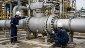
Isolate All Energy
Before anyone works around the valve, make sure nothing can move unexpectedly and no stored pressure can be released.
- Block remote OPEN and CLOSE commands.
- Isolate electrical power where required.
- Isolate pneumatic or hydraulic supply where required.
- Check for stored pressure in accumulators.
- Account for stored spring energy in spring-return actuators.
- Confirm the required pipeline pressure condition.
- Treat the body cavity as pressurized until it has been safely checked.
A pipeline gauge showing 0 bar only tells you what is happening at that gauge point. It does not prove that the valve body cavity, actuator cylinder, accumulator, or connected tubing is also at 0 bar.
In U.S. workplaces, OSHA 29 CFR 1910.147 requires control of hazardous stored or residual energy during covered servicing and maintenance work.[1]
Never put a hand, cloth, camera, or tool inside the bore while the actuator can move.
Verify the Valve and Service Data
Start with the nameplate and compare it with the approved datasheet and piping documents. The goal is simple: make sure the valve installed in the line is the valve the project actually called for.
| Check | What to Confirm |
|---|---|
| Tag | Correct valve for the line |
| Size | For example NPS 12 / DN300, NPS 24 / DN600, or NPS 36 / DN900 |
| Pressure class | Matches the project specification |
| Body material | Matches the datasheet |
| Seat type | Soft seated or metal seated |
| End connection | Flanged or butt welded |
| Actuator | Correct model and fail action |
| Pressure | Actual upstream and downstream pressure |
| Temperature | Within the valve design condition |
Common pipeline-valve pressure classes include ASME Class 150, 300, 600, 900, 1500, and 2500. These class numbers are not fixed pressure values. The allowable pressure still depends on material and temperature. ASME B16.34 covers pressure-temperature ratings, materials, testing, dimensions, tolerances, and marking for valves within its scope.[2]
ISO 14313:2025 applies to pipeline valves in ASME Classes 150, 300, 600, 900, 1500, and 2500 and covers design, manufacturing, materials, welding, assembly, testing, documentation, and process control.[3]
Also identify whether the valve is floating or trunnion mounted. The difference between floating and trunnion-mounted ball valves affects how pressure loads the ball and seats.
Seat construction matters too. Soft-seated and metal-seated ball valves do not respond the same way to dirt, temperature, and surface damage. Soft seats, in particular, can be damaged by sharp construction debris.
Calculate Differential Pressure
Use the upstream and downstream readings together. Differential pressure is the difference between them.
| Upstream | Downstream | Differential Pressure |
|---|---|---|
| 100 bar | 100 bar | 0 bar |
| 100 bar | 95 bar | 5 bar |
| 100 bar | 0 bar | 100 bar |
The upstream gauge reads 100 bar in all three cases, but the load on the valve is not the same. Use the real differential pressure when checking actuator sizing and operating torque.
Remove Shipping Restraints
Large valves and actuators are often secured for transport. Before the first stroke, look for anything that was fitted only to stop movement during shipping.
- transport pins
- locking bolts
- steel brackets
- tie bars
- temporary supports
- protective blocks
- actuator transport restraints
Do not remove a part just because it looks temporary. A permanent travel stop, valve lock, actuator lock, or structural bracket can look very similar.
Use the valve drawing, actuator manual, packing drawing, or warning tag to identify the part before removing it.
If a transport restraint is left in place, the actuator can push against a solid stop. That can damage the coupling, key, gearbox, actuator, or electric motor.
Inspect the Bore and Ball
The bore should be empty and clean before the ball moves across the seats.
Remove:
- plastic covers
- wood
- foam
- tape
- desiccant bags
- cleaning cloths
- loose hardware
Then check the ball and visible seat area for:
- weld spatter
- metal chips
- hard particles
- rust
- dents
- deep scratches
Where the damage sits matters. A deep scratch across the seat contact path is more serious than a light mark outside the sealing area because it can create an internal leak path.
Do not use wire brushes, abrasive paper, steel scrapers, or screwdrivers on the sealing surface unless the valve manufacturer allows it.
Clean the Pipeline
A new valve can be damaged during its first closing stroke if the pipeline still contains construction debris.
Look for:
- weld slag
- grinding dust
- rust scale
- sand
- metal chips
- welding wire
- paint flakes
- gasket fragments
- nuts and bolts
Do not rely only on a note saying the line was flushed. Check the actual result through:
- flushing discharge
- temporary strainer condition
- filter or screen condition
- collected debris
- visual bore inspection where possible
Many ball valves are kept fully open during pipeline flushing so debris passes through the main bore instead of being dragged across the seat. Use the position specified by the valve manufacturer.
If welding, grinding, cutting, or pipe modification took place after the last flush, check the line again.
Remove Hydrotest Water
Hydrotest water can remain in places that are not obvious from the outside.
Check:
- the body cavity
- drain passages
- low points
- instrument tubing
Remove or dry it as required by the project. Water left behind can lead to corrosion, freezing damage, or process contamination.
Check Piping Alignment and Support
The valve should fit the piping. The piping should not be pulled into position through the valve.
Check:
- flange faces are aligned
- bolt holes line up
- pipe centerlines match
- the valve is not being pulled sideways
- supports carry the intended weight
- the actuator is not twisting the valve body
Do not use flange bolts to pull badly misaligned piping together.
Look for pipe load if:
- the valve becomes harder to operate after flange tightening
- the stem begins moving unevenly
- the pipe moves when the valve rotates
- the valve body moves when piping load is released
- a support is not carrying weight as intended
If the valve worked normally before the flange bolts were tightened and then became noticeably harder to operate, check the piping before blaming the valve internals.
Do not apply a made-up rule such as “2 mm maximum misalignment” to every installation. Use the value specified by the piping design or valve manufacturer.
Do not support the valve from positioners, tubing, switch boxes, grease fittings, solenoids, or other small accessories.
Check the Stem, Coupling, Actuator, and Stops
Follow the parts that actually carry the turning force:
actuator → gearbox or adapter → coupling → stem → ball
Stem
- Check for bending.
- Check for corrosion or impact damage.
- Check keys and keyways.
- Check for loose stem connections.
A flat, slot, or keyway on the stem does not always show ball position. Use the valve drawing rather than guessing.
Coupling
- Confirm full engagement.
- Confirm the coupling is centered.
- Check keys or splines.
- Check mounting bolts.
- Look for cracks or movement marks.
Actuator Position
The actuator and valve should normally be connected in matching positions. For example, a valve mechanically in CLOSED should normally be paired with an actuator in its corresponding CLOSED position unless the OEM procedure specifies another method.
If the two positions do not match, the result can be incomplete travel, wrong position signals, overtravel, or coupling damage.
Travel Stops
A normal ball valve uses about 90° of rotation from fully closed to fully open.
Do not change a factory-set stop simply because an indicator looks slightly wrong.
If the valve cannot reach full travel, check these first:
- debris
- coupling position
- actuator position
- pipe load
- actuator supply
- mechanical interference
A travel stop sets the end position. It is not a way to add more sealing force.
Check Lubrication and Injection Points
Before connecting a grease gun or sealant pump, identify exactly what each fitting is for. A gearbox lubrication point, seat injection port, and stem injection port do different jobs.
For valve-specific maintenance differences, see trunnion-mounted ball valve lubrication and maintenance.
Gearbox
- Check the specified lubricant type.
- Check oil or grease level where applicable.
- Look for leakage.
- Check fill and drain plug condition.
- Check the storage period.
A gearbox already filled by the manufacturer may not need extra lubricant before startup.
Seat Injection
Seat injection ports may be used for emergency sealant, cleaning compound, or a defined maintenance procedure.
Do not treat them as routine grease points unless the valve instructions say so.
Stem Injection
Before injection, confirm:
- the exact fitting
- where the injected material goes
- approved product
- required quantity
- maximum injection pressure
- temperature range
- seal compatibility
- process-fluid compatibility
Do not mix lubricants or sealants unless compatibility is known.
Check Actuator Supply and Signals
Pneumatic
Record:
- supply pressure before movement
- supply pressure during breakaway
- regulator setting
- air leakage
Also check the filter, tubing, solenoid, exhaust ports, and speed-control valves.
Record pressure in bar or psi. Do not assume every actuator should run at a fixed value such as 6 bar. Use the actuator sizing data.
Hydraulic
Record hydraulic pressure in bar or MPa where a reliable gauge is available.
Check:
- correct hydraulic fluid
- fluid level
- pressure setting
- hoses and tubing
- leakage
- accumulator pressure
- air trapped in the system
Electric
Check:
- voltage
- frequency
- phase where applicable
- grounding
- terminal connections
- motor direction
- limit-switch settings
- torque-switch settings
If motor-current data are available, record the current in amperes during startup and travel. The value is useful later when you compare the same actuator under similar conditions.
Position Signals
Check the whole signal path instead of looking only at the actuator display:
OPEN command → ball physically opens → local indicator shows OPEN → remote system shows OPEN.
Repeat the same check for CLOSED.
Also confirm the required fail action: fail open, fail closed, or fail in place.
Check the Body Cavity
Identify every cavity-related fitting before the valve goes into service:
- body vent
- body drain
- upstream seat injection port
- downstream seat injection port
- stem injection port
Check that caps, plugs, valves, extension tubes, and threaded joints are undamaged and correctly configured.
Do not open a vent or drain just to see whether pressure is present.
Liquid trapped in a closed space can build high pressure when heated. The U.S. Chemical Safety Board notes that fluid-filled vessels and piping require pressure-relief consideration because thermal expansion can lead to loss of containment.[4]
For the same issue inside a ball valve, see ball-valve cavity pressure and thermal expansion.
SPE Seats
SPE means Single Piston Effect. In a typical self-relieving SPE design, sufficiently high cavity pressure can move the seat away from the ball and relieve fluid toward the lower-pressure side.
DPE Seats
DPE means Double Piston Effect. A DPE seat can keep sealing when pressure acts from either side, so a DPE arrangement may need another way to control cavity overpressure.
Do not assume every trunnion valve relieves cavity pressure in the same way. Check the valve sectional drawing and IOM.
DBB and DIB
If the valve is specified as DBB, DIB-1, or DIB-2, confirm the actual seat arrangement before using the cavity vent for an isolation or seat test.
A DN600 PN63 DIB-1 trunnion valve is one example of why the seat arrangement should come from the actual specification rather than be guessed from valve size.
Perform the First Stroke
Where the OEM and project procedure allow it, carry out the first stroke at low or near-zero differential pressure.
Watch the full 90° travel while the valve moves.
| Watch | Acceptable Condition | Stop and Check |
|---|---|---|
| Movement | Smooth rotation | Repeated hesitation or stopping |
| Sound | Normal actuator/gear noise | Grinding, scraping, knocking, impact |
| Coupling | No visible movement | Slip, lift, or side movement |
| Bracket | Stable | Flexing or shifting |
| Piping | Stable | Movement caused by valve rotation |
| Actuator load | Within expected behavior | Torque trip or sudden pressure/current rise |
If resistance keeps appearing at the same point, note the approximate valve angle. For example, a torque rise near 45° means the problem is around the middle of a 90° stroke. The 45° value is only a location example, not a universal failure limit.
Compare Torque Through the Stroke
Do not judge a large ball valve against one generic torque number.
Record torque in N·m or lbf·ft when reliable data are available, then compare it with the OEM torque sheet for the actual valve, pressure, and temperature.
High Torque at Breakaway
If the valve is hard to start but becomes easier once moving, check:
- differential pressure
- seat friction
- long storage
- corrosion
- piping load
- actuator condition
High Torque in Mid-Stroke
If the torque rises after the valve has already started moving, check:
- debris
- internal interference
- ball or seat damage
- coupling or stem alignment
High Torque Near Full Open or Closed
If the torque rises mainly near the end position, check:
- travel-stop setting
- overtravel
- obstruction
- actuator setup
- seat contact
A repeatable torque spike at the same valve angle gives you more useful information than simply writing “high torque.”
Verify Full Open and Full Closed
At full open:
- confirm the ball reaches the designed open position
- confirm local and remote signals show OPEN
- check bore alignment where safely visible
Full opening matters even more on piggable lines. A ball left partly across the bore can obstruct or damage a pipeline pig.
At full closed:
- confirm the designed mechanical position is reached
- confirm local and remote signals show CLOSED
- check for abnormal end-of-travel torque
If the valve does not fully close, find the mechanical cause before changing the travel stop.
Test Under Pressure
Once the low-load stroke is acceptable, introduce pressure according to the approved commissioning procedure.
Do not assume a successful low-pressure stroke proves the actuator can move the valve at maximum design differential pressure.
For example, a valve that operates normally at:
- 100 bar upstream
- 95 bar downstream
- 5 bar differential pressure
has not yet demonstrated the same operating condition as:
- 100 bar upstream
- 0 bar downstream
- 100 bar differential pressure
Use the actual actuator-sizing condition, not the example values above, as the acceptance basis.
When a formal metallic-valve pressure or closure-tightness test is required, ISO 5208:2015 covers pressure-boundary integrity and closure-tightness testing and states that product-standard requirements take precedence where they differ.[5]
External Leakage
Check:
- stem seals
- body joints
- flange gaskets
- vents and drains
- threaded fittings
- injection fittings
Make sure a wet area is active leakage and not leftover hydrotest water.
Internal Seat Leakage
Check for:
- debris on the seat
- incomplete closure
- ball damage
- seat damage
- incorrect pressure direction
- incorrect test setup
External stem leakage and internal seat leakage are different faults and need different checks. The difference is covered in more detail in this stem-leak vs seat-leak diagnosis.
Measure Opening and Closing Time
Record both stroke times in seconds.
Example commissioning baseline:
- Opening time: 42 s
- Closing time: 45 s
Those values are examples, not universal limits. What matters is the comparison on the same valve. If the same valve later closes in 80 s under similar conditions, the change is worth checking.
On liquid lines, closing time can affect water hammer. U.S. Army Corps of Engineers guidance includes valve closure time directly in pressure-rise calculations. One worked example in EM 1110-1-4008 compares sudden closure with a closure 10 times slower, showing why valve speed and system conditions need to be considered together.[6]
Do not change pneumatic or hydraulic speed controls simply to make commissioning faster. Use the stroke time required by the process or safety design.
Check Butt-Weld Valves After Welding
Before first operation, check the valve and nearby pipe for:
- weld spatter inside the bore
- grinding debris
- metal particles
- remaining purge materials
- visible heat damage
Soft seats and elastomer seals can be damaged by too much heat. Use the welding temperature limit and ball position required by the valve manufacturer. Do not apply one universal value to every valve design.
If welding or grinding took place after the last pipeline cleaning, clean the line again.
Check Valves After Long Storage
A valve that has never been used can still change during storage.
If it has been stored for months or years, check:
- corrosion
- damaged coating
- moisture inside actuator or electrical enclosures
- bore and flange protection
- stem condition
- gearbox lubricant
- actuator seals and tubing
- cable glands
- missing plugs or caps
If preservation oil or corrosion inhibitor remains, confirm whether it must be removed before process service.
Record the Baseline
| Item | Record | Example |
|---|---|---|
| Valve travel | Degrees | About 90° |
| Upstream pressure | bar / MPa / psi | 100 bar |
| Downstream pressure | bar / MPa / psi | 95 bar |
| Differential pressure | bar / MPa / psi | 5 bar |
| Pneumatic supply | bar / psi | Actual measured value |
| Hydraulic pressure | bar / MPa | Actual measured value |
| Breakaway torque | N·m / lbf·ft | Compare with OEM data |
| Motor current | A | Actual measured value |
| Opening time | seconds | Example: 42 s |
| Closing time | seconds | Example: 45 s |
The example numbers show what to record. They are not acceptance limits for another valve.
Also record:
- valve tag and date
- travel-stop settings
- limit-switch settings
- regulator settings
- external leakage
- seat-test result where required
- problems found
- corrective action
First-Operation Checklist
- All hazardous energy controlled
- Correct valve and actuator confirmed
- Pressure, temperature, and differential pressure checked
- Shipping restraints identified and removed where required
- Bore and ball clean
- Pipeline clean
- Hydrotest water removed as required
- Piping aligned without forcing the valve
- Valve and actuator properly supported
- Stem and coupling undamaged
- Valve and actuator positions matched
- Travel stops checked
- Gearbox lubrication checked
- Seat and stem injection ports identified
- Pneumatic, hydraulic, or electrical supply checked
- Fail position confirmed
- Local and remote signals verified
- Vent and drain correctly configured
- Body-cavity pressure behavior understood
- First 90° stroke smooth
- No grinding, knocking, or structural movement
- Full open confirmed
- Full closed confirmed
- Torque recorded where available
- Opening and closing time recorded
- Pressurized operation checked where required
- External leakage checked
- Internal seat leakage checked where required
- Commissioning baseline recorded
Finally
Keep the first-operation record with the valve data. At minimum, keep upstream and downstream pressure, differential pressure, actuator supply, breakaway torque where available, motor current for electric actuators, and opening and closing time. A valve that repeatedly develops high torque at the same point in its 90° stroke needs inspection. A valve that becomes harder to move only after flange tightening should make you check piping alignment first. Example times such as 42 s open and 45 s closed are useful as a baseline for that valve; they are not universal limits. Future changes in these numbers are often more useful than a one-time pass/fail result.







