
| Valve condition | Practical interval | Approx. checks/year |
|---|---|---|
| Clean, stable, non-regulated service | 6–12 months may be used for planning | 1–2 |
| Critical or severe service | 3–6 months may be justified | 2–4 |
| Frequently operated valve | Use operating history and condition data | Condition-based |
| Valve showing abnormal torque, travel, leakage, or actuator faults | Investigate and repair as required | Do not rely on the calendar |
| Regulated pipeline valve | Follow the applicable legal interval | As required by regulation |
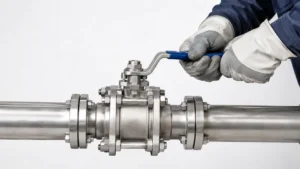
Use These Five Inputs to Set the Interval
The calendar is only one part of the decision. In practice, the interval should come from the items below, starting with anything that is mandatory.
| Input | What to check | Effect on the interval |
|---|---|---|
| Regulation | Mandatory inspection or operating interval | Never exceed the legal maximum |
| OEM and site procedure | Valve manual, actuator manual, O&M procedure, safety-system test plan | Use the specified interval if one is given |
| Isolation duty | What happens if the valve cannot close? | Higher consequence normally needs closer verification |
| Service condition | Solids, wax, corrosion, water, temperature, flooding, salt, dust | Faster deterioration may justify shorter checks |
| Condition trend | Torque, stroke time, leakage, actuator behavior, position feedback | Worsening data requires investigation |
An ESD or SIS valve should not be put on a 3- or 6-month cycle just because it is used for emergencies. Its approved functional-safety and proof-test program comes first. IEC 61511 covers the specification, design, installation, operation, and maintenance of safety instrumented systems in the process industries.[1]
If the valve already has a known fault, a shorter calendar interval is not the fix. Find the cause, repair it where needed, verify the result, and then decide how closely it should be watched.
Choose Partial or Full Stroke Based on What You Need to Prove
| Test | What it can show | What it does not prove |
|---|---|---|
| Visual inspection | External leakage, corrosion, damage, access problems | That the valve can move |
| Partial stroke | The valve and actuator can start moving through the tested travel | Full travel or seat tightness |
| Full stroke | Complete mechanical travel | Leak-tight shutoff by itself |
| Position check | Local and remote indication agree with field position | Seat tightness |
| Seat or leakage test | Shutoff performance under the test conditions | Future actuator reliability |
A conventional quarter-turn ball valve has about 90° of full travel. A 20° movement is about 22% of that travel. This is only a mathematical example; it is not a recommended partial-stroke setting.
Partial stroke is useful when you want to confirm that the valve can start moving without fully shutting the line. It may expose a seized valve, actuator trouble, loss of instrument pressure, a control fault, a position-feedback error, or an unusually slow response. What it cannot tell you is whether the valve can finish the remaining travel or whether the seats will actually stop flow.
A full stroke checks the whole movement. It is more likely to expose resistance near the closed position, incorrect stops, gearbox trouble, weak actuator output, or incomplete travel. Because full closure can disturb pipeline operation, it should only be done when the approved operating procedure allows it.
Check Movement, Position, and Shutoff Separately
| Failure | Typical signs | Likely area to check |
|---|---|---|
| Valve will not move | High torque, actuator stall, no travel | Seats, stem, bearings, gearbox, actuator |
| Valve reaches position but leaks | Flow continues after closure | Seats, ball surface, debris, bypass path |
| Valve moves but indication is wrong | Local and remote positions disagree | Limit switch, transmitter, coupling, wiring, SCADA |
A valve may complete its 90° travel and still leak through damaged or contaminated seats. That is why “closed,” “operable,” and “leak-tight” should not be treated as the same result.
When the valve moves normally but fluid still passes through it, the next step is to work out where the leak is coming from. This ball valve leakage troubleshooting guide covers the main checks for stem leakage, seat leakage, and other common field symptoms.
Shorten Checks for These Service Conditions
| Condition | What it can do to the valve |
|---|---|
| Wax or heavy deposits | Increase resistance around the seats |
| Sand, rust, or scale | Abrade ball and seat surfaces |
| Slurry or hard solids | Increase erosion and seat damage |
| Water or corrosive contamination | Attack internal parts, stems, gearboxes, or actuators |
| Salt or coastal exposure | Accelerate external corrosion |
| Flooding | Damage gearboxes, switches, electrical parts, and valve-box access |
| Rarely operated emergency isolation duty | Provides little normal operating data before demand |
Two valves of the same size can behave very differently if one sees clean gas and the other sees wax, sand, water, or corrosive material. Service conditions matter because they affect the parts that actually move and seal.
Valve construction matters too. The main differences are shown in this comparison of trunnion-mounted and floating ball valves.
For example, a soft-seated trunnion ball valve may use SPE/SPE, DPE/DPE, or SPE/DPE seat arrangements. Seat direction affects sealing and how trapped cavity pressure is handled, so the exact valve drawing and manual matter during maintenance.
Compare Torque Under Similar Pressure Conditions
Breakaway torque is the torque needed to start moving a stationary valve. If it keeps rising under similar test conditions, something in the valve or drive train may be getting harder to move.
| Test | Breakaway torque | Change from baseline |
|---|---|---|
| January, Year 1 | 720 N·m | Baseline |
| July, Year 1 | 790 N·m | +9.7% |
| January, Year 2 | 910 N·m | +26.4% |
| July, Year 2 | 1,080 N·m | +50.0% |
Here, the valve still moves, but breakaway torque has increased by 360 N·m, or 50%. That is a clear reason to look at deposits, corrosion, stem friction, bearings, gearbox condition, seat damage, or contamination. It is not a universal failure limit.
Pressure can change the torque reading, so two tests are only useful to compare when the operating conditions are reasonably similar.
| Test | Upstream | Downstream | Differential pressure |
|---|---|---|---|
| Test A | 70 bar | 68 bar | 2 bar |
| Test B | 70 bar | 20 bar | 50 bar |
Test B has 25 times the differential pressure of Test A. If Test B produces a higher torque reading, that does not automatically mean the valve has deteriorated.
Each torque record should include upstream pressure, downstream pressure, differential pressure, fluid temperature, flow condition, and valve position.
For actuator sizing or troubleshooting, it also helps to separate break torque, running torque, and reseating torque instead of treating valve torque as one fixed number.
Check Actuator Margin Before It Disappears
| Condition | Actuator output | Valve torque demand | Difference |
|---|---|---|---|
| Healthy example | 1,500 N·m | 800 N·m | 700 N·m |
| Later example | 1,500 N·m | 1,300 N·m | 200 N·m |
In the first example, actuator output is 87.5% higher than valve demand. In the second, it is only about 15.4% higher. The valve may still work, but the difference has dropped from 700 N·m to 200 N·m.
That simple comparison is useful for spotting the issue, but real actuator sizing is not based on one number. Valve torque and actuator output both change through the stroke. Minimum pneumatic or hydraulic supply, electric supply, temperature, spring condition, gearbox losses, and maximum allowable drive-train torque also matter.
HSE guidance for emergency isolation states that actuators should be sized to operate the valve at the maximum pressure that may occur in service.[2]
If valve torque rises, increasing actuator force can hide the symptom without fixing the reason. Check the valve first.
Track Stroke Time as a Trend
| Test | Closing time | Change from 18 s baseline |
|---|---|---|
| Baseline | 18 s | — |
| Later test | 21 s | +16.7% |
| Later test | 27 s | +50.0% |
| Later test | 34 s | +88.9% |
A move from 18 to 34 seconds means the valve now takes almost 89% longer to close. That is much more useful than simply recording “passed.”
Possible causes include:
- lower pneumatic supply pressure;
- restricted air flow;
- hydraulic leakage;
- actuator seal wear;
- solenoid problems;
- higher valve torque;
- electric motor problems; or
- gearbox damage.
A much faster stroke can also be a warning if no one intended to change the actuator settings, damping, or control behavior.
There is no universal “good” stroke time. Compare each valve with its own healthy baseline and required operating time.
Do Not Create a Pressure Surge During Full Closure
On a liquid line, closing a valve changes fluid velocity. If that change happens too quickly, pressure can rise sharply. U.S. pipeline regulations define surge pressure as pressure created by a change in stream velocity caused by events such as pump shutdown or valve closure.[3]
Before changing closure speed, check:
- normal flow velocity;
- pipeline length;
- fluid properties;
- pump operating condition;
- total closing time; and
- how quickly the valve reduces flow during each part of its stroke.
Do not shorten closing time just to finish the exercise sooner.
Record These Conditions Before Moving the Valve
- valve ID and physical location;
- normal valve position;
- pipeline and fluid service;
- upstream pressure;
- downstream pressure;
- current flow condition;
- pump or compressor status;
- bypass position;
- actuator supply condition;
- expected effect of valve movement; and
- whether the control room must be involved.
Before applying force, inspect the accessible parts for body or stem leakage, corrosion, loose components, damaged coatings, broken actuator tubing, hydraulic leaks, damaged cables, gearbox water entry, or missing identification.
U.S. gas and hazardous-liquid pipeline operators within the applicable scope must maintain written operating and maintenance procedures.[4][5]
Stop the Exercise if These Signs Appear
- starting torque is much higher than the normal baseline;
- movement is jerky or suddenly releases after sticking;
- the actuator stalls;
- grinding or abnormal vibration occurs;
- stem or body leakage starts or increases;
- hydraulic or pneumatic pressure drops unexpectedly;
- motor overload or abnormal current appears;
- pipeline pressure changes unexpectedly;
- the valve does not reach the required position; or
- field and remote position signals disagree.
Using a longer wrench on a difficult manual valve is not a repair. It only puts more load into the stem, gearbox, coupling, seats, and operator.
Verify the Whole Valve-and-Actuator Chain
| Operator type | Items to check |
|---|---|
| Pneumatic | Air pressure, tubing, leaks, solenoid, actuator seals, stroke time |
| Hydraulic | Hydraulic pressure, leaks, accumulator where used, controls, stroke time |
| Electric | Supply voltage, motor, gearbox, torque settings, limit switches, alarms |
| Manual | Handwheel or operating nut, gearbox, stem extension, corrosion, tool access |
Where the design allows, compare field position, local indication, limit-switch status, transmitter output, and SCADA indication.
For U.S. hazardous-liquid pipelines, 49 CFR §195.116 requires each valve other than a check valve to have a way to clearly indicate its position.[6]
A CLOSED signal tells you what the position system is reporting. It does not prove that the seats are leak-tight.
Control Trapped Body-Cavity Pressure Before Maintenance
Many trunnion-mounted ball valves have a body cavity between the seats. Process fluid can remain trapped there even when the valve is closed.
Do not assume that a closed valve has a depressurized body cavity.
SPE and DPE seat arrangements handle cavity pressure differently. The relationship between the ball, seats, cavity, and bleed connection is shown in this explanation of trunnion ball valve internal structure and DBB operation.
Before venting, draining, opening a body fitting, replacing a seal, or carrying out intrusive work, use the valve drawing, OEM instructions, and site isolation procedure.
HSE guidance on plant isolation includes draining and venting as part of controlling hazardous substances during maintenance.[7] OSHA’s hazardous-energy rule also requires control of stored energy during covered servicing and maintenance work.[8]
Keep Buried Valves Accessible
- remove soil or debris covering the operating point;
- drain flooded valve boxes where the approved procedure allows;
- check stem extensions for damage;
- check valve-box alignment;
- keep identification visible;
- confirm the correct operating tool is available; and
- keep the access route usable.
A valve may be mechanically sound and still be useless in an emergency if the crew cannot find it, reach it, or operate it quickly.
U.S. gas distribution rules require certain operating and emergency valves to be readily accessible, while U.S. hazardous-liquid rules require valves within their scope to be accessible to authorized personnel and protected from damage or tampering.[9][10]
Reset the Baseline After Repairs or Major Changes
Create a new healthy reference after:
- actuator replacement;
- gearbox replacement;
- seat or stem-seal repair;
- major valve overhaul;
- a change in process fluid;
- a major pressure or temperature change;
- a change in closing speed;
- a control-system modification;
- flooding;
- fire;
- impact or excavation damage; or
- abnormal overpressure.
Once the equipment changes, the old numbers may no longer be a fair comparison. Start a new baseline for the repaired or modified setup.
Record These Values Every Time
- valve ID;
- date and technician;
- starting and final position;
- amount of travel;
- upstream and downstream pressure;
- differential pressure;
- temperature when relevant;
- breakaway torque;
- running or reseating torque where available;
- actuator supply pressure or electrical condition;
- stroke time;
- local and remote position indication;
- leakage observations;
- abnormal noise or vibration;
- corrective work; and
- retest status.
| Item | 2025 | 2026 | Change |
|---|---|---|---|
| Breakaway torque | 840 N·m | 1,080 N·m | +28.6% |
| Stroke time | 22 s | 31 s | +40.9% |
| Air pressure | 6.1 bar | 6.0 bar | -1.6% |
| Observed leakage | None | None | No change |
Here, torque increased by 28.6% and stroke time by 40.9%, while air pressure changed by only 1.6%. That does not identify the fault on its own, but it makes increasing mechanical resistance more important to check than a large loss of actuator air supply.
Investigate These Changes Before the Next Scheduled Exercise
- breakaway torque rises clearly above the valve’s normal trend;
- stroke time changes without an operating reason;
- the actuator stalls or hesitates;
- the valve cannot reach its required position;
- position signals disagree;
- new stem, body, or seat leakage appears;
- water enters the gearbox or actuator enclosure;
- actuator faults repeat;
- corrosion becomes serious; or
- the service becomes dirtier, more abrasive, or more corrosive.
Find the cause → repair if required → verify the result → establish the next monitoring interval.
U.S. Regulatory Minimums
The figures below apply only where the cited U.S. federal pipeline rules apply. They are not worldwide exercise intervals.
| Pipeline / valve type | Current federal requirement |
|---|---|
| Gas transmission valve that might be required during an emergency | Inspect and partially operate at least once each calendar year; interval not more than 15 months |
| Gas distribution valve needed for safe operation | Check and service at least once each calendar year; interval not more than 15 months |
| Hazardous-liquid mainline valve | Inspect at least twice each calendar year; interval not more than 7½ months |
49 CFR §192.745 requires applicable gas transmission valves to be inspected and partially operated at intervals not exceeding 15 months, but at least once each calendar year. An inoperable valve requires prompt remedial action unless an alternative valve is designated.[11]
49 CFR §192.747 requires applicable gas distribution valves to be checked and serviced at intervals not exceeding 15 months, but at least once each calendar year.[12]
Under the current 49 CFR §195.420, applicable hazardous-liquid mainline valves must be inspected at least twice each calendar year, with intervals not exceeding 7½ months. Full closure is not required for this inspection; a minimum 25% closure is sufficient unless operating information requires additional closure for reliability.[13]
The 25% value belongs to that specific U.S. rule. It is not a general instruction to move every pipeline ball valve by exactly 25%.
Regulatory check date: August 2026.
API 6D Does Not Set the Exercise Interval
API currently lists API Specification 6D, 25th Edition, including Addendum 3 issued in March 2025.[14]
API 6D covers requirements including valve design, manufacturing, materials, welding, quality control, assembly, testing, marking, documentation, and process controls.[15]
It does not create a universal field rule such as “exercise every six months.” Factory testing and installed-valve maintenance are different jobs. This explanation of API 6D shell, seat, and functional testing shows what factory tests check before a valve enters service.
Use Lubrication and Sealant Only When the Valve Design Calls for It
Grease or sealant should not be injected automatically every time the valve is exercised.
| Item | Correct approach |
|---|---|
| Gearbox lubricant | Use the specified type and service interval |
| Stem lubrication | Use only if the design provides for it |
| Seat sealant injection | Use the specified product, pressure, and procedure |
| Emergency sealant system | Do not treat it as routine lubrication |
If torque increases, injecting an unknown product may hide the symptom and create another problem. The material may be incompatible with the seats or process fluid.
If a valve repeatedly needs sealant to maintain shutoff, record how often it happens and check the seat condition. The difference between normal lubrication, sealant injection, and actual seal repair is covered in this trunnion ball valve maintenance guide.
Finally
For stable, non-regulated service, 6–12 months gives roughly 1–2 planned checks per year; 3–6 months gives about 2–4 and may suit harsher service. Regulations and OEM procedures come first. The useful part of each exercise is the condition data: pressure, torque, stroke time, actuator behavior, position, and leakage. A move from 840 to 1,080 N·m is a 28.6% torque increase, while 22 to 31 seconds is a 40.9% stroke-time increase. Those changes are worth investigating before the valve reaches the point where it can no longer perform its isolation duty.







