
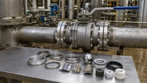
Check the complete valve rather than only the pressure-containing body. The ball, stem, seat rings, springs, bearings, body cavity, drain holes and elastomer seals can fail before the main body wall becomes too thin. CARILO’s API 6D forged ball valve guide explains the main full-bore, reduced-bore and fire-safe construction options used in pipeline service.
Start with the Water
Dry CO₂ is much less corrosive to carbon steel than CO₂ mixed with liquid water. Once CO₂ dissolves in water, it changes the water chemistry and supports corrosion reactions at the steel surface.[1]
A simplified reaction is:
CO₂(aq) + H₂O ⇌ H₂CO₃
The real water phase is more complex. It may contain bicarbonate, carbonate, dissolved iron, chlorides, oxygen, H₂S, organic acids, treatment chemicals and solid particles. These substances can change the corrosion rate and the type of damage.
A valve can be harder to protect than straight pipe because water may remain in:
- The body cavity
- Seat pockets
- Stem and trunnion bores
- Spring pockets
- Drain and vent passages
- Seal grooves
- The rear side of seat rings
These areas may remain wet after the main pipeline has drained. A closed valve cavity may also receive little or no fresh corrosion inhibitor.
Iron carbonate may form on carbon steel and slow the average corrosion rate. It is not a permanent protective coating. Flow, sand, low pH and valve movement can damage it. Tests on X65 steel have also found localized corrosion beneath developing and apparently complete iron-carbonate layers.[2]
A low average corrosion rate therefore does not prove that a seat pocket, sealing surface or narrow drain passage is safe.
Define the CO2 Service
Wet CO₂ pipelines do not all carry the same fluid. The source of the CO₂ changes the impurities, water conditions and operating risks.
| Service | Common conditions | Valve areas at risk |
|---|---|---|
| Oil and gas production | Produced water, chlorides, H₂S, organic acids, sand and corrosion inhibitor | Seat pockets, ball surface, springs, drains and bearings |
| Wet CO₂ gas | Shutdown condensation, low-point water and intermittent wetting | Lower body cavity, seat pockets and stem bore |
| CCS pipeline | Water excursions, oxygen, NOx, SOx, rapid pressure reduction and phase changes | All wetted surfaces, elastomers, vents and relief passages |
For CCS service, define both normal fluid composition and possible off-specification conditions. DNV-RP-F104 covers CO₂ properties, safety, materials, design, construction and operation as connected parts of a CO₂ pipeline system.[3]
Water, oxygen and nitrogen or sulfur oxides can interact and create more severe corrosion than pure CO₂ and clean water alone.[4]
A CCS specification should state:
- Normal impurity limits
- Maximum water content
- Possible off-specification composition
- Maximum off-specification duration
- Water-monitoring method
- Shutdown and restart requirements
Collect the Design Data
Use operating ranges rather than one normal pressure and temperature.
| Required data | Why it matters |
|---|---|
| Minimum and maximum pressure | Body rating, seat load, phase behavior and decompression |
| Full temperature range | Corrosion, toughness, seat strength and actuator output |
| CO₂ concentration | Gas-phase partial pressure and fluid behavior |
| Water content | Dew point and condensation risk |
| Free-water rate | How long and how much of the valve remains wet |
| Chloride concentration | Water conductivity, pitting and crevice corrosion |
| Water pH and alkalinity | Carbon steel corrosion and iron-carbonate formation |
| H₂S concentration and partial pressure | Sour-service cracking risk |
| Oxygen, NOx and SOx | Oxidizing and mixed-acid corrosion |
| Organic acids | Carbon steel corrosion and deposit stability |
| Sand concentration and particle size | Ball coating, seats, bearings and drain blockage |
| Flow rate and pressure drop | Erosion, turbulence and local cooling |
| Corrosion inhibitor | Whether protected carbon steel is practical |
| Blowdown rate | Low temperature and rapid gas decompression |
| Operating cycles | Seat, coating, bearing and actuator life |
The data should cover normal operation, start-up, low flow, shutdown, blocked-in conditions, cleaning, water carryover and emergency depressurization.
Calculate CO2 Partial Pressure
For a simple gas mixture, approximate CO₂ partial pressure can be calculated by multiplying absolute pressure by the CO₂ mole fraction.
| Total pressure | CO₂ content | Approximate CO₂ partial pressure |
|---|---|---|
| 50 bar absolute | 10 mol% | 5 bar |
| 80 bar absolute | 20 mol% | 16 bar |
| 100 bar absolute | 20 mol% | 20 bar |
| 120 bar absolute | 50 mol% | 60 bar |
For example:
100 bar × 0.20 = 20 bar CO₂ partial pressure
This calculation is useful for initial gas-phase screening. It does not show whether water is present, how much of the valve is wet or whether the water contains chlorides, oxygen or acids.
Dense-phase CO₂ requires a suitable thermodynamic model. Fugacity, water solubility, phase changes and impurity distribution cannot be fully described by simple multiplication.
Assess the Corrosion Risk
Do not judge valve life from one average corrosion rate. The review should include:
- Uniform corrosion during normal operation
- Localized corrosion during shutdown
- Under-deposit corrosion beneath sand or scale
- Corrosion during inhibitor failure
- Attack at CRA-overlay edges
- Crevice corrosion behind seats and seals
- Erosion-corrosion caused by particles or high velocity
The following table shows calculated uniform wall loss. It does not include pitting, crevice corrosion, erosion or abnormal operation.
| Average corrosion rate | 10-year loss | 20-year loss | 30-year loss |
|---|---|---|---|
| 0.05 mm/year | 0.5 mm | 1.0 mm | 1.5 mm |
| 0.10 mm/year | 1.0 mm | 2.0 mm | 3.0 mm |
| 0.20 mm/year | 2.0 mm | 4.0 mm | 6.0 mm |
| 0.50 mm/year | 5.0 mm | 10.0 mm | 15.0 mm |
A rate of 0.10 mm/year appears small, but it produces 2.0 mm of uniform loss over 20 years. A local pit can grow faster than this average value and may damage a seat pocket before the main body wall reaches its minimum thickness.
Assess corrosion over the full temperature range. The highest rate may occur at an intermediate temperature where reactions are active but the iron-carbonate layer is still thin or unstable.
A straight-pipe corrosion result should not be copied directly to every valve surface. A valve has tighter crevices, longer liquid retention and less inhibitor renewal.
Include Inhibitor Failure
When carbon steel depends on corrosion inhibitor, include periods when injection is unavailable or does not reach the valve cavity.
For example, assume:
- Inhibited corrosion rate: 0.05 mm/year
- Uninhibited corrosion rate: 1.0 mm/year
- Inhibitor failure: 30 days
The calculated uninhibited loss during the 30-day failure is:
1.0 mm/year × 30 ÷ 365 = 0.082 mm
One event may appear small, but five similar events would add about 0.41 mm of uninhibited loss. This calculation still does not include local pitting beneath deposits.
Check H2S Separately
H₂S introduces cracking risks that are different from wet CO₂ wall loss. H₂S does not automatically mean the valve needs Alloy 625 overlay.
ISO 15156-3 provides requirements for selecting and qualifying corrosion-resistant alloys and other alloys in applicable H₂S-containing oil and gas environments. It covers cracking mechanisms rather than uniform or localized corrosion loss.[5]
The sour-service review should include:
- H₂S partial pressure
- Water pH
- Chlorides
- Temperature
- Material hardness
- Heat treatment
- Cold work
- Weld and heat-affected-zone condition
- Applied stress
A material can meet ISO 15156 cracking limits and still corrode too quickly. Check cracking resistance and metal-loss corrosion separately.
Decide Whether Carbon Steel Is Enough
Carbon steel can be a practical valve-body material when the corrosion risk is understood and controlled.
It may be acceptable when:
- Free-water exposure is limited
- The corrosion model fits the actual fluid
- Inhibitor reaches important wetted surfaces
- Inhibitor failure time is included
- Localized corrosion is not expected to control valve life
- The cavity can be drained and inspected
Corrosion allowance only protects against expected wall loss. It does not repair a damaged ball surface, stop crevice corrosion behind a seat or protect a narrow hole from deep pitting.
CARILO’s carbon steel, stainless steel and duplex ball valve comparison explains the main cost, strength and corrosion differences between common valve-body materials.
Choose the Body Protection
| Body arrangement | When it may fit | Main concern |
|---|---|---|
| Carbon steel | Controlled water exposure and acceptable calculated corrosion | Localized attack and inhibitor dependence |
| Carbon steel with CRA overlay | Large or high-pressure valves in more corrosive service | Coverage, dilution, defects and final machining |
| Solid CRA | Severe, long-life or difficult-to-inspect service | Cost, lead time and manufacturing control |
Forged construction can improve material consistency, but forging alone does not provide corrosion resistance. The grade, heat treatment, overlay and inspection still control suitability. CARILO’s API 6D trunnion-mounted ball valve guide provides more detail on high-pressure pipeline construction.
Specify the Overlay
The purchase order should not state only “Alloy 625 overlay on wetted parts.” The sectional drawing must show exactly which surfaces are protected.
- Main flow bore
- Body cavity
- End bores
- Seat pockets and supports
- Stem and trunnion bores
- Drain and vent passages
- Injection passages
- Cavity-relief passages
- Fluid-exposed seal recesses
Small holes may be difficult to overlay. They may need CRA sleeves, CRA inserts or a revised body design. The transition from CRA to carbon steel should not end at the bottom of a wet cavity.
Specify minimum finished thickness after machining. Deposited thickness is not enough because rough machining, grinding, defect removal, repair and final finishing remove part of the layer.
The following example assumes a project requirement of 3.0 mm minimum finished overlay. The 3.0 mm value is an example, not a universal industry requirement.
| Measurement point | Finished thickness | Result |
|---|---|---|
| Main body bore | 3.4 mm | Pass |
| Body cavity | 3.2 mm | Pass |
| Seat pocket | 3.1 mm | Pass |
| Drain-passage transition | 2.8 mm | Below the 3.0 mm requirement |
An acceptable average thickness cannot hide one local thin point. The 2.8 mm area requires engineering review or approved repair followed by repeat inspection.
The first weld layer mixes with the carbon steel body. This dilution increases iron content and changes the final deposit. The specification should identify:
- Filler-metal classification
- Required finished deposit chemistry
- Maximum permitted iron content
- Sampling locations
- Number of readings
- Requirements after repair
Do not automatically apply wrought UNS N06625 chemistry limits to a weld overlay. Match the limits to the selected filler metal, qualified welding procedure and finished deposit.
Final inspection should include visual examination, liquid-penetrant testing, thickness mapping, chemistry checks, PMI and repair records. Cracks, exposed carbon steel, lack of fusion and areas below minimum thickness require approved repair and repeat inspection.
Avoid Small Exposed Steel Areas
A small carbon steel area connected to a much larger CRA surface may corrode quickly when conductive water is present.
Common locations include:
- Overlay pinholes
- Machined-through areas
- Uncovered drain holes
- Thread roots
- Overlay transition edges
- Gaps around CRA inserts
A CRA ball and stem do not protect an unlined carbon steel body cavity.
Select the Trim Materials
“Stainless steel trim” is too vague. Identify the ball, stem, seat rings, trunnions, bearings, springs, pins, keys, internal fasteners and seal retainers.
| Material | Possible use | Points to check |
|---|---|---|
| 316L | Clean water with controlled chlorides and moderate temperature | Pitting, crevice corrosion, oxygen and chloride stress corrosion cracking |
| Duplex 2205 | Higher strength and better chloride resistance than 316L | Temperature, H₂S, hardness, welding and phase balance |
| Super duplex | More severe chloride-containing water | Low pH, H₂S, crevices and manufacturing quality |
| Alloy 625 | Overlay and severe chloride or mixed-impurity service | Product form, hardness, weld dilution and cost |
| Higher nickel alloy | Low-pH or mixed oxidizing and reducing acid service | Service-specific test data |
PREN can help compare stainless steel compositions, but it does not prove service suitability. It does not fully include pH, H₂S, welding condition, stress, crevice shape or surface finish.
CARILO’s side-entry ball valve material guide explains how body and trim materials are reviewed together.
Protect the Ball and Seat Rings
The ball must keep a smooth and round sealing band. Small pits, scratches or coating defects can cause leakage and high torque before body-wall loss becomes important.
Possible ball constructions include:
- Solid CRA ball
- Carbon steel ball with full CRA overlay
- CRA ball with a hard coating
- CRA-overlaid ball with a coated sealing band
A hard coating should provide wear resistance. It should not be the only corrosion barrier over an unsuitable substrate.
Specify:
- Coating process and composition
- Minimum and maximum coating thickness
- Permitted porosity
- Bond strength
- Final surface roughness
- Ball roundness
- Maximum permitted surface defects
The ball and seat surfaces also need a suitable hardness difference to reduce galling. The seat-ring material must suit the water chemistry, rear-seat crevice, contact stress, sliding movement and H₂S limits.
Choose Soft or Metal Seats
Soft seats can provide low leakage and lower torque. Common options include PTFE-based compounds, PCTFE and PEEK.
PTFE has low friction and broad chemical resistance but can creep or extrude under sustained pressure. PEEK normally provides higher strength and extrusion resistance, but it is less flexible and more sensitive to ball finish, alignment and seat load.
For every soft seat, confirm:
- Minimum and maximum temperature
- Maximum closing pressure difference
- Reverse-pressure condition
- Extrusion gap
- CO₂ absorption
- Rapid-decompression resistance
- Expected operating cycles
- Required leakage rate
Metal seats may be preferred when sand, scale, high temperature, frequent operation or erosive pressure drop can damage a polymer seat. They usually need hard-faced surfaces, precision lapping, higher actuator torque and a clearly stated leakage acceptance.
| Illustrative operating pattern | Example annual cycles | Main concern |
|---|---|---|
| Main pipeline isolation | 5–20 cycles/year | Long idle time and high break torque |
| Regular process isolation | 50–200 cycles/year | Seat and bearing wear |
| Frequent switching | 1,000 or more cycles/year | Coating, seat and actuator life |
These cycle counts are examples of operating patterns, not valve qualification limits. Actual qualification should use the required project cycle count and pressure difference.
Check the Elastomers
High-pressure CO₂ can diffuse into elastomers. During rapid pressure reduction, trapped gas can expand and cause blisters, internal cracks, surface splits or permanent property loss.
ISO 23936-2 gives requirements and procedures for selecting and qualifying elastomeric materials used in oil and gas production equipment.[6]
Rapid gas decompression performance depends on pressure, temperature, exposure time, decompression rate, specimen shape and the exact elastomer formulation.[7]
Material names such as HNBR, FKM, FEPM or FFKM do not identify one fixed compound. Ask for test records for the actual formulation.
Review:
- Stem seals
- Body-joint seals
- Seat-ring seals
- Backup rings
- Injection-fitting seals
Control Cavity Pressure
A closed ball valve can trap liquid in its body cavity. If the liquid warms, its expansion may raise cavity pressure above line pressure.
The valve needs a defined relief arrangement, such as:
- Self-relieving seats
- An external cavity-relief valve
- Relief to one side of the pipeline
- Relief to a closed collection system
Confirm seat action, relief direction, set pressure, reverse-pressure behavior and discharge location. Check whether sand, corrosion products, ice or dry CO₂ could block the passage.
Terms such as SPE, DPE, DBB and DIB should be checked against the actual sectional drawing. The label alone does not show how the cavity behaves under every pressure direction.
Check Depressurization
Rapid depressurization can produce two-phase flow and sharp cooling. Tests on a 50 km, 24-inch CO₂ pipeline showed that pressure and temperature change significantly during depressurization from a supercritical starting condition.[8]
Industrial-scale testing has also shown that throttling can increase dry-ice accumulation near an outlet and raise the risk of freezing or blockage.[9]
The following comparison is illustrative. It does not define a safe blowdown time.
| Example pressure change | Example duration | Main review |
|---|---|---|
| 100 bar to 10 bar | 5 minutes | Severe cooling, RGD and possible dry ice |
| 100 bar to 10 bar | 30 minutes | Lower pressure-change rate, but a transient calculation is still required |
| 100 bar to 10 bar | 2 hours | Lower thermal shock, but cavity and vent behavior still need review |
The real temperature depends on fluid composition, starting phase, valve position, restriction size, heat transfer and pipeline geometry.
The study should define:
- Minimum valve metal temperature
- Minimum seat and seal temperature
- Possible dry-ice locations
- Vent and relief-line blockage risk
- Actuator output at the lowest temperature
- Maximum permitted blowdown rate
Choose the Valve Construction
A floating ball valve uses line pressure to push the ball against the downstream seat. This design is common in smaller sizes, but seat load and operating torque can increase as pressure difference rises.
A trunnion-mounted valve supports the ball while movable seat rings respond to pressure. This design is common for large sizes, high pressure, pigging and controlled cavity relief.
For piggable service, check the minimum finished bore through the ball, seat rings and end transitions. “Full bore” on a quotation does not prove that the intended pig can pass.
A fully welded side-entry body has fewer external joints but may be difficult to repair internally. A bolted or top-entry body may be easier to service but adds body seals and bolting.
CARILO’s floating versus trunnion ball valve guide compares the two constructions by size, pressure and operating torque.
Check the Pressure Rating
Read the valve pressure rating at the actual design temperature, not at room temperature. ASME B16.34-2025 covers pressure-temperature ratings, dimensions, tolerances, materials, examination, testing and marking for applicable metallic valves.[10]
The complete valve limit is the lowest limit of the body, bolting, seats, packing, seals, coating and actuator. A high pressure class does not override the temperature limit of a polymer seat.
Size the Actuator
Use the complete valve torque curve rather than one catalog value.
Ask for:
- Break-to-open torque
- Running torque
- End-to-close torque
- Torque at maximum pressure difference
- Torque at minimum and maximum temperature
- Maximum allowable stem torque
For example, assume the worst-case valve break torque is 2,000 N·m and the project uses a 40% actuator sizing margin:
2,000 N·m × 1.40 = 2,800 N·m
The actuator should provide at least 2,800 N·m at the minimum available supply pressure in this example. The 40% margin is an example, not a universal requirement.
Also confirm that actuator output remains below the maximum allowable stem and drive-train torque. A larger actuator is not automatically safer if it can twist the stem or damage the seats.
Add allowances for long idle periods, deposits, sand, seat swelling, packing load, bearing friction and low supply pressure. CARILO’s valve torque curve guide explains break, running and closing torque in more detail.
Set the Factory Test Plan
API Specification 6D, 25th Edition is the base pipeline-valve specification. Addendum 3 was issued on March 5, 2025.[11]
ISO 14313:2025 supplements API 6D, 25th Edition. API 6D requirements remain applicable together with the additions stated in ISO 14313.[12]
Standard shell and seat tests confirm factory pressure integrity and closure performance. They do not prove long-term resistance to wet CO₂.
A wet CO₂ inspection plan may include:
- Material certificates and traceability
- PMI
- Overlay procedure qualification
- Finished overlay thickness mapping
- Final overlay chemistry
- Liquid-penetrant examination
- Hardness testing
- Duplex phase checks
- Ball roundness and surface roughness
- Coating inspection
- Seat leakage testing
- Torque measurement
- Cavity-relief testing
ISO 5208 specifies examinations and tests used to verify the pressure-boundary integrity and closure tightness of metallic industrial valves.[13]
State the test medium, test pressure, test direction, holding time and permitted leakage. CARILO’s API 6D ball valve testing guide explains the main test records to request before shipment.
After hydrostatic testing, drain and dry the body cavity, vents, drains and injection passages. Trapped test water can start corrosion before the valve is installed.
Check External Leakage
ISO 15848-1 covers type-testing procedures and classifications for external leakage from valve stem seals and body joints. The effects of corrosion are outside its scope, so it does not replace the wet CO₂ material review.[14]
Specify external-emission qualification separately from seat leakage and internal corrosion requirements.
Review Three Selection Examples
The following examples show how process data change the valve requirements. They are not universal material limits.
Wet gas isolation example: A DN200 Class 600 valve operates at 80–95 bar and 25–45°C. The gas contains 15 mol% CO₂ with intermittent water carryover. Design life is 20 years, and the valve operates fewer than 50 times per year.
A possible arrangement is a carbon steel body with a calculated corrosion allowance, corrosion-resistant ball and stem, qualified soft seats and a drainable cavity. The final choice depends on the water composition, shutdown condensation and inhibitor access.
Produced-water example: A DN300 Class 900 valve operates at 60–85 bar and 35–70°C. The water contains 20,000 mg/L chlorides and suspended solids, while the valve operates about 200 times per year.
This service needs a separate review of body overlay, CRA seat rings, spring material, hard-coated ball surfaces and particle damage. A soft seat may still be possible in some cases, but it should not be selected without solids and pressure-difference testing.
CCS example: An NPS 16 Class 900 valve operates at 95–120 bar and 20–40°C in high-concentration dense-phase CO₂. The illustrative project water limit is 50 ppmv, design life is 25 years, and emergency pressure reduction is from 100 bar to 10 bar in 30 minutes.
The review should include off-specification water, oxygen and acid-gas conditions, full CRA-overlay coverage, rapid-decompression-qualified elastomers, minimum metal temperature, cavity relief and actuator output during the blowdown case.
Use a Buying Checklist
| Area | Information to include |
|---|---|
| Fluid | Gas composition, water, chlorides, pH, H₂S, oxygen, acids and solids |
| Operating limits | Pressure, temperature, blowdown rate, design life and operating cycles |
| Valve design | Size, class, bore, body style, seat action, drains, vents and relief direction |
| Materials | Body, overlay, ball, stem, seat rings, springs, coating, seats and elastomers |
| Overlay | Coverage drawing, filler metal, finished thickness, chemistry and repair limits |
| Actuator | Torque curve, output curve, supply pressure, fail position and stroke time |
| Inspection | PMI, NDE, pressure tests, leakage tests, torque test and drying records |
Watch the Valve in Service
| Observed problem | Possible causes | First checks |
|---|---|---|
| Internal leakage | Ball damage, particles, seat corrosion or incomplete travel | Seat test, ball surface and actuator travel |
| Rising torque | Deposits, seat swelling, bearing corrosion or coating damage | Torque trend, cavity drain and internal inspection |
| Stem leakage | Seal damage, rapid decompression, low-temperature contraction or stem corrosion | Seal condition, compound and pressure history |
| Blocked drain or vent | Sand, scale, corrosion products, ice or dry CO₂ | Passage inspection and depressurization review |
| Unexpected cavity pressure | Trapped liquid or blocked relief path | Seat action and cavity-relief test |
Trend opening torque, closing torque, seat leakage and the condition of drained liquid. A steady torque increase or repeated seat leakage may warn of internal damage before the valve becomes impossible to operate.
CARILO’s ball valve leakage troubleshooting guide explains how to separate stem leakage, body-joint leakage and internal seat leakage.
Conclusion
Choose a wet CO₂ valve by checking water, impurities, corrosion loss and pressure changes before selecting materials. A uniform rate of 0.10 mm/year produces 2.0 mm loss in 20 years, but it does not cover deep pits in seat pockets or drains. If CRA overlay is required, define every covered surface, final thickness and deposit chemistry; a local 2.8 mm reading fails a 3.0 mm minimum even when the average is higher. Match the ball, seats, springs and elastomers to the same service. Before approval, verify cavity relief, minimum blowdown temperature, seat leakage and actuator torque at the lowest available supply pressure.







