
For early layout, a non-cold-box ball valve may have a centerline-to-stuffing-box height near 200–350 mm. A cold-box valve may require 400–800 mm or more. These are planning ranges, not standard minimum dimensions.
The final height must be no less than the largest of three values: the project or standard minimum, the height required to clear the insulation, and the height required to keep the packing warm enough. The selected design must also pass checks for stem twist, actuator weight, installation angle and thermal movement.
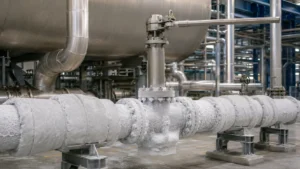
What Sets the Length?
Nominal valve size is only one input. Two DN 50 valves can have different body diameters, pressure classes, stem sizes and packing locations.
| Installation | Main Requirement |
|---|---|
| Insulated cryogenic line | Body radius, insulation thickness and maintenance space |
| Valve inside a cold box | Centerline-to-wall distance and outside access |
| Inclined valve stem | Liquid position inside the bonnet and approved stem angle |
| Large actuator or gearbox | Stem twist, bonnet bending load and support |
| Valve exposed to cold vapor | Packing, actuator and accessory temperatures |
| Custom long extension | Thermal evidence and mechanical strength |
CARILO supplies forged cryogenic ball valves for low-temperature applications. The exact bonnet dimension should still be confirmed from the project conditions and approved drawing.
Compare Fluid Temperatures
The fluid temperature affects the bonnet temperature gradient, but it does not directly give the required length. The figures below are rounded reference temperatures at or near normal boiling pressure.
| Cryogenic Fluid | Approximate Temperature | Selection Note |
|---|---|---|
| LNG | About −161°C to −162°C | Actual temperature varies with LNG composition and pressure |
| Liquid oxygen | About −183°C | Also requires oxygen-compatible materials and cleanliness |
| Liquid argon | About −186°C | Close to the lower part of the ISO 28921 temperature range |
| Liquid nitrogen | About −196°C | Near the lower limit of ISO 28921-1 |
| Liquid hydrogen | About −253°C | Outside the −196°C scope of ISO 28921-1 |
U.S. Department of Energy LNG research uses temperatures near −161°C for cryogenic LNG conditions.[1] Normal boiling-point data for oxygen, argon, nitrogen and hydrogen are available from the NIST Chemistry WebBook and NIST reference tables.[2][3][4][5]
Define the Dimension
“Bonnet length” can describe several different dimensions:
- Body surface to packing gland
- Body surface to actuator mounting face
- Valve centerline to top of stuffing box
- Fabricated extension-tube length
- Overall valve height
These values cannot be compared directly. A supplier quoting a 300 mm tube may place the packing lower than another supplier quoting a 300 mm centerline-to-stuffing-box height.
For project comparison, a practical reference is the distance from the valve centerline to the top of the stuffing box.
The stuffing box is the metal chamber that holds the packing rings. The packing gland presses the rings against the stem and chamber wall. The actuator mounting face is above the packing and should not be used as a substitute for the packing position.
Ask the manufacturer to show these points on the drawing:
- Valve centerline
- Maximum body radius
- Bottom and top of the packing set
- Packing gland and gland bolts
- Top of the stuffing box
- Actuator mounting face
- Extension inside and outside diameters
- Drain, vent and seat-injection connections
- Overall height
Large trunnion-mounted valves often have wider bodies, larger stems and more external fittings than floating valves. Their insulation envelope should come from the actual drawing. See the trunnion-mounted ball valve selection guide for related construction details.
Check the Standards
ISO 28921-1:2022 covers the design, dimensions, materials, fabrication and production testing of metallic isolation valves used from −50°C down to −196°C. It includes ball and plug valves, but it does not replace project-specific insulation and clearance checks.[6]
ISO 28921-2:2015 is the current published standard for low-temperature type testing. It verifies a defined valve design under stated test conditions. It does not automatically qualify every bonnet length, stem diameter, packing system or installation angle.[7]
ISO 28921-2 also states that an actuator is not evaluated unless it is an integral part of the valve. A valve test report does not automatically qualify a separately selected actuator, positioner or solenoid.
A second edition of ISO 28921-2 is under development and is intended to replace the 2015 edition. Purchase documents should therefore state the exact published edition required by the project.[8]
ANSI/MSS SP-134-2025 covers cryogenic valves and includes requirements for body and bonnet extensions.[9]
BS 6364:1984 still appears in older catalogues, but BSI lists it as withdrawn from July 2021. It should not be presented as the current standard for a new project unless the contract specifically requires it.[10]
ASME B16.34 covers pressure-temperature ratings, materials, dimensions, examination, testing and marking for applicable industrial valves. ASME lists B16.34-2025 as the current edition.[11]
ASME B31.3 covers process piping in petroleum, chemical, hydrogen and cryogenic plants. It applies to the surrounding piping, supports, movement, fabrication, examination and testing rather than directly calculating the bonnet length.[12]
A standard minimum does not prove that the actual valve:
- Clears the finished insulation
- Keeps the packing within its approved temperature range
- Fits through the cold-box wall
- Leaves enough tool space
- Supports the selected actuator
- Has acceptable stem twist
Measure the Insulation
The packing gland should normally remain outside the permanent cryogenic insulation.
Use the complete finished insulation thickness, including:
- Main insulation material
- Vapor-retarder layers
- Outer vapor barrier
- Sealant and overlap areas
- Metal or polymer jacket
- Removable cover
- Fire-protection layer where required
- Installation tolerance
Do not add an assumed 10 or 20 mm without checking the project insulation drawing. Different systems use different jackets, joints and removable covers.
Measure from the valve body, not from the connected pipe.
For example:
- Pipe outside radius: 30 mm
- Valve body radius: 85 mm
- Finished insulation thickness: 100 mm
If the calculation starts from the pipe radius, the finished insulation boundary will be shown 55 mm too low. The gland may then be partly covered after installation.
Use the highest body surface that must remain insulated. Include body bolts, drain valves, vents and body joints when they increase the insulation-box height.
Leave Tool Space
A bonnet that only reaches the insulation surface is too short for normal maintenance.
The exposed gland area needs room for:
- Leak inspection
- Temperature measurement
- Gland-bolt tightening
- Socket and torque-wrench access
- Packing removal
- Gland-follower removal
- Actuator coupling removal
A provisional allowance of 50–100 mm above the finished insulation can be used during early layout. It is not a standard minimum. Replace it with an actual tool-access and packing-removal check before drawing approval.
Packing replacement needs more space than routine tightening because the gland follower and packing rings must move upward along the stem.
Check:
- Side access to every gland bolt
- Vertical removal space
- Clearance from nearby piping and steelwork
- Space for insulated gloves
- Access after fitting the removable insulation cover
Calculate the Height
A simple geometric check is:
Hgeometry = Rbody + Tinsulation + Caccess + Goffset
- Hgeometry: required centerline-to-bonnet height
- Rbody: centerline to the highest insulated body surface
- Tinsulation: complete finished insulation thickness
- Caccess: clear maintenance space above the insulation
- Goffset: distance from the lowest maintenance point to the selected measurement point
Compare this result with the project and thermal requirements:
Hselected = maximum of Hgeometry, Hstandard and Hthermal
- Hstandard: minimum required by the project specification or applicable standard
- Hthermal: minimum height supported by thermal analysis or representative test data
This is a layout check, not an ISO, MSS or ASME formula. Select the shortest approved production length that is not below the controlling value.
Compare Worked Examples
The following examples show how the calculation works. They are not standard bonnet dimensions for every valve of the stated size.
| Example | Body or Wall Height | Insulation | Access and Offset | Calculated Height | Possible Production Length |
|---|---|---|---|---|---|
| DN 25 insulated valve | 65 mm | 80 mm | 90 mm | 235 mm | 250 mm |
| DN 50 insulated valve | 88 mm | 100 mm | 92 mm | 280 mm | 300 mm |
| DN 100 cold-box valve | 520 mm to outside wall | Included in wall depth | 120 mm | 640 mm | 650 mm |
For the DN 25 example:
65 + 80 + 90 = 235 mm
If the manufacturer offers an approved 250 mm production length, it leaves 15 mm above the calculated geometric requirement.
For the DN 50 example:
88 + 100 + 60 + 32 = 280 mm
If thermal analysis requires 295 mm, the geometric result no longer controls. The next approved production length may be 300 mm.
For the DN 100 cold-box example:
520 + 80 + 40 = 640 mm
A 650 mm approved length may be selected, but only after checking stem strength, actuator load and cold-box movement.
For LNG-specific seat, material and bonnet considerations, see the LNG cryogenic ball valve selection guide.
Check Packing Temperature
The bottom packing ring must remain within the approved temperature range of the complete stem-sealing system.
Do not use a general rule stating that every packing box must remain above 0°C. Some packing systems work below freezing. Others contain secondary seals, bearings or lubricants with higher minimum temperatures.
Check the temperature limits of:
- Primary packing rings
- Lip seals
- O-rings
- Stem bearings
- Stem guides
- Thrust washers
- Live-loading springs
- Lubricants where used
The lowest-rated part can limit the complete assembly. A packing material may have a wide temperature range while a secondary seal or lubricant does not.
Ask whether the supplier’s rating applies to:
- The packing material alone
- The complete stem-sealing assembly
- Short exposure or continuous operation
- A stated pressure and number of cycles
- A tested valve or only a material datasheet
A useful temperature record should include:
| Temperature Point | Supplier Value |
|---|---|
| Minimum process temperature | _____ °C |
| Minimum valve-body temperature | _____ °C |
| Lowest predicted bottom-packing temperature | _____ °C |
| Minimum qualified stem-seal temperature | _____ °C |
| Temperature margin | _____ °C |
| Actuator mounting temperature | _____ °C |
The temperature margin can be checked as:
Temperature margin = predicted bottom-packing temperature − minimum qualified temperature
For example, if the bottom packing is predicted to reach −25°C and the complete seal system is qualified to −40°C:
−25 − (−40) = 15°C margin
This 15°C figure is an example, not a universal project requirement. The required margin must come from the project specification or manufacturer’s approved design basis.
Check Cooldown
A valve can pass a steady cold hold and still leak during cooldown, operation or warm-up.
| Stage | Possible Change | Check |
|---|---|---|
| Cooldown | Body contracts before the upper bonnet | Stem leakage, temperature rate and movement |
| Cold hold | Seal hardness and friction stabilize | Packing temperature, leakage and torque |
| Cold cycling | Stem friction and elastic twist change | Ball travel and actuator margin |
| Warm-up | Metal expands and trapped liquid vaporizes | Leakage, moisture entry and cavity pressure |
| Repeated cycles | Packing load may reduce | Leakage trend and gland condition |
The test record should show the time of each valve operation and the packing temperature at that time. A report stating only that the body reached −196°C does not show whether the packing stayed within its approved range.
Check Heat Transfer
Two bonnets of the same length can produce different packing temperatures.
Heat transfer also depends on:
- Stem diameter and material
- Bonnet wall thickness and material
- Internal gas space
- Stem guides and bearings
- Actuator brackets
- Ambient temperature
- Wind and cold-vapor exposure
- Installation angle
A larger stem cross-section increases heat conduction. Its effect on packing temperature depends on the complete stem, bonnet, insulation and surrounding environment.
An upward bonnet is designed to maintain a gas or vapor space between the cryogenic liquid and the packing. The actual liquid position still depends on pressure, valve orientation, flow and cooldown conditions.
A useful thermal model should include:
- Minimum fluid temperature
- Minimum ambient temperature
- Stem and bonnet dimensions
- Stem and bonnet materials
- Guide and bearing positions
- Insulation termination
- Cold-vapor exposure
- Actuator bracket geometry
Check the Stem Angle
Cryogenic ball valves are normally installed with the stem pointing upward. This helps maintain the intended gas or vapor space below the packing.
The allowable angle is product-specific. It depends on the internal bonnet shape, pressure, fluid level and test arrangement.
State the angle in degrees from vertical:
- 0°: vertical
- 15°: slightly inclined
- 45°: strongly inclined
- 90°: horizontal
“Installed on horizontal piping” is not enough because it describes the pipe rather than the stem.
For a strongly inclined or horizontal stem, increasing the bonnet length alone may not stop liquid from moving toward the packing. The actual angle must be approved by the valve manufacturer.
Check Stem Twist
In most extended-bonnet designs, a longer bonnet also needs a longer torque-transmitting stem or stem extension.
A longer stem twists more under the same torque unless its diameter, material or support arrangement is changed. Excessive twist can allow the actuator to reach its stop before the ball is fully open or closed.
Keep these movements separate:
- Actuator travel
- Upper stem rotation
- Actual ball rotation
The supplier should confirm:
- Breakaway torque at maximum pressure difference
- Dynamic operating torque
- Actuator output at minimum supply pressure
- Stem stress
- Stem twist angle
- Actual ball travel at the actuator stops
A long extension may require a larger stem, stronger material, additional guides or a thicker extension tube.
Check Actuator Loads
A longer bonnet moves the actuator’s center of gravity farther from the valve body. The same actuator weight then creates a larger bending load.
For example, assume:
- Actuator and bracket mass: 75 kg
- Distance from the support point to the center of gravity: 0.5 m
The static force is:
75 × 9.81 = 736 N
The static bending moment is:
736 × 0.5 = 368 N·m
The 368 N·m value includes only the static weight. Wind, vibration, seismic movement, valve operation and pipe movement can increase the design load.
A heavy actuator on a long cold-box bonnet may need an independent support. The support must carry the weight without pushing the actuator and stem out of alignment.
The support must also allow pipe contraction. A rigid support can create more load than an unsupported actuator. Actuator and bid-document requirements are discussed further in the industrial ball valve procurement guide.
Check Thermal Movement
The body, stem, bonnet, bolts, bracket and support may use different materials. They do not contract by the same amount during cooldown.
This can change:
- Packing compression
- Stem position
- Guide clearance
- Coupling alignment
- Actuator mounting load
- Cold-box penetration clearance
Use material data for the actual alloy and temperature range. Do not apply one general contraction percentage to every part.
For a simple example, assume approved material data show 0.30% total contraction over the operating temperature range. A 1,000 mm component would shorten by:
1,000 × 0.003 = 3 mm
The 0.30% value is an example input, not a universal stainless-steel contraction value. The cold-box penetration, actuator support and coupling must accommodate the actual calculated movement.
Stop the Insulation
Permanent insulation should stop below the packing gland.
Covering the gland can cause:
- Hidden stem leakage
- Frozen gland fasteners
- Moisture inside the insulation
- Vapor-barrier damage
- Corrosion under insulation
- Blocked maintenance access
The valve drawing should show the highest permitted insulation position. The insulation designer should provide the vapor-barrier and removable-cover details.
A removable cover is acceptable when it can be removed without damaging the main vapor barrier and does not trap water or leaked fluid.
Relieve Cavity Pressure
Liquid trapped inside a closed ball-valve cavity can warm and expand. This may create high cavity pressure even when the main pipeline pressure remains stable.
The valve needs an approved relief method, such as:
- Self-relieving seat
- Relief hole in the ball
- Single-seat arrangement
- External relief connection
A drilled-ball arrangement may give the valve a required flow direction. The body marking and piping drawing must show which side faces upstream.
Bonnet length cannot replace cavity-pressure relief. Related pipeline valve requirements are discussed in the API 6D ball valve specification guide.
Test the Design
The bonnet should be supported by a thermal calculation or representative cryogenic test.
The test procedure should state:
- Valve size and pressure class
- Bonnet length and measurement reference
- Stem and packing arrangement
- Test temperature and pressure
- Cooling medium and method
- Valve installation angle
- Actuator and bracket arrangement
- Soak time and operating cycles
- Seat and stem leakage limits
- Temperature sensor positions
- Warm-up inspection
| Test | Purpose | Limit |
|---|---|---|
| Type test | Qualifies a valve design or family | Only covers the stated design range |
| Production test | Checks the supplied valve | May not repeat the complete type test |
| Project test | Checks unusual project conditions | Must be defined in the purchase order |
For a custom extension, confirm that the test covers the same or a representative:
- Bonnet length
- Stem diameter and material
- Packing system
- Guide arrangement
- Installation angle
- Actuator bracket
- Size and pressure-class range
A short DN 25 test valve does not automatically qualify a 650 mm extension on a large cold-box valve.
Review the Report
The test report should give measured values, not only the word “passed.”
Check for:
- Valve model and serial number
- Drawing number and revision
- Bonnet length
- Packing arrangement
- Test pressure and temperature
- Temperature sensor locations
- Operating-cycle timing
- Seat leakage result
- Stem leakage result
- Bottom packing temperature
- Installation angle
- Instrument calibration
Warning signs include:
- No packing sensor location
- Only valve-body temperature recorded
- Tested bonnet different from the offered design
- Installation angle missing
- Different packing arrangement
- Drawing revision not matching the supplied valve
- No torque or ball-travel result
These checks can be written into the project valve inspection and test plan before manufacturing begins.
Provide Complete RFQ Data
| Item | Required Information |
|---|---|
| Fluid | LNG, liquid nitrogen, liquid oxygen, liquid argon or another stated fluid |
| Phase | Liquid, gas or two-phase |
| Temperature | Normal, cooldown and minimum design temperature |
| Pressure | Design, operating and maximum differential pressure |
| Valve | DN/NPS, pressure class, floating or trunnion design |
| Installation | Insulated line, vessel nozzle or cold box |
| Insulation | Finished thickness and termination detail |
| Cold box | Valve centerline to finished outside wall |
| Movement | Calculated pipe and valve displacement |
| Stem angle | Degrees from vertical |
| Packing | Qualified temperature and leakage requirement |
| Clearance | Tool and packing-removal space |
| Actuator | Type, mass, supply pressure and temperature limit |
| Duty | Cycle frequency, emergency position and operating time |
| Standards | Exact standard numbers and editions |
| Testing | Type, production and project-specific requirements |
| Cavity relief | Relief method and required flow direction |
Handle Liquid Hydrogen Separately
Liquid-hydrogen valves must not use LNG or liquid-nitrogen bonnet dimensions without separate review.
ISO 28921-1 stops at −196°C. NIST lists hydrogen’s normal boiling point as 20.27 K, equal to approximately −252.9°C.[13]
MSS published SP-166-2026 specifically for testing valves used in cryogenic hydrogen service.[14]
ASME B31.12 applies to piping and pipelines handling gaseous hydrogen, hydrogen mixtures and piping in liquid-hydrogen service.[15]
Liquid-hydrogen service requires separate checks for materials, leakage, seals, heat transfer and testing. See the liquid-hydrogen cryogenic valve overview for related product information.
Check After Installation
Before startup, confirm:
- The stem is at the approved angle
- The valve direction matches the cavity-relief design
- The insulation stops at the approved point
- The gland remains accessible
- The actuator support allows thermal movement
- The indicated position matches the actual ball position
During the first controlled cooldown, record:
- Frost boundary
- Bottom packing and gland temperature
- Actuator temperature
- Stem leakage
- Opening and closing time
- Limit-switch indication
- Bonnet or bracket movement
Frost alone does not prove leakage. Cold metal can freeze moisture from the air. Frost above the expected cold boundary should still be checked with temperature measurement and an approved leak-detection method.
Possible signs of a bonnet that is too short include:
- Frost repeatedly reaching the gland
- Stem leakage during cold operation
- Frozen gland bolts
- Low-temperature actuator faults
- Repeated ice inside the insulation
Possible signs of a long but mechanically weak arrangement include:
- Actuator travel without full valve closure
- Inconsistent open or closed positions
- Bonnet or bracket vibration
- Coupling misalignment
- Abnormal stem wear
When leakage is found, first determine whether it comes from the stem or the seats. See the ball valve leakage troubleshooting guide for a practical field-check sequence.
Avoid Common Errors
- Different measurement points: one supplier quotes tube length while another quotes centerline-to-stuffing-box height.
- Pipe radius used: the body is wider than the connected pipe, so the insulation boundary is calculated too low.
- Nominal insulation used: the jacket, vapor barrier and removable cover are omitted.
- Actuator temperature used: a warm mounting plate is treated as proof that the packing is warm enough.
- Unrelated test report used: a short, small valve is used to qualify a large cold-box design.
- Site extension added: the stem or tube is lengthened without checking strength and twist.
- Rigid cold-box support: the penetration prevents normal thermal movement.
- Wrong valve direction: a directional cavity-relief arrangement faces downstream.
Approval Checklist
- The bonnet measurement points are shown on the drawing
- The actual valve-body radius is used
- The finished insulation thickness is confirmed
- Tool and packing-removal space is available
- The bottom packing temperature is acceptable
- The actual stem angle is approved
- Stem twist and ball travel are verified
- Actuator and external loads are acceptable
- The cold-box penetration allows movement
- The cavity-relief direction is confirmed
- The test report represents the supplied design
- The final length is shown on the certified drawing
Conclusion
A non-cold-box cryogenic ball valve may use a bonnet near 200–350 mm, while a cold-box installation may need 400–800 mm or more. These figures are only for early layout. Calculate the height from the actual body radius, finished insulation, 50–100 mm provisional tool space and packing position. Compare that result with the standard minimum and the required bottom-packing temperature. A 75 kg actuator positioned 0.5 m from its support already creates about 368 N·m of static bending moment, so long bonnets also need mechanical checks. Final approval must come from the certified drawing and representative thermal or cryogenic test evidence.







