
- Confirm the source: Make sure the fluid is coming from the stem, not a body joint, vent, drain, flange, or nearby tube.
- Adjust only when permitted: Tighten the gland in small, equal steps and stop at the approved setting.
- Repair recurring leaks: If leakage returns after thermal cycling, replace the packing and inspect the stem, springs, actuator alignment, and piping load.
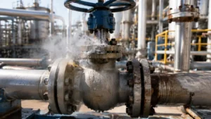
How the Stem Seal Works
The valve stem connects the ball to the handle, gearbox, or actuator. Because the stem must rotate, it passes through an opening in the valve body. Packing is compressed around the stem to prevent process fluid from escaping through this opening.
A typical stem-sealing system contains:
- PTFE, graphite, or composite packing rings
- A packing follower
- A gland plate
- Gland studs and nuts
- Washers or Belleville springs
- Anti-extrusion rings
- O-rings or secondary seals
- A graphite fire-safe backup seal in some designs
The nuts or springs push the gland plate downward. The gland plate pushes the follower, and the follower compresses the packing. The packing then presses inward against the stem and outward against the packing-chamber wall.
If packing pressure is too low, fluid can travel along the stem. If it is too high, stem friction rises and the actuator may not complete the full valve stroke.
The stem seal must not be confused with the stem-retention system. Many ball valves use an internal shoulder or anti-blowout stem design. A nut that holds the stem in place is not always a packing-adjustment nut. The internal arrangement also differs between floating and trunnion-mounted valves. This guide to trunnion-mounted ball valve selection explains the main construction and application differences.
API 6D specifies requirements for pipeline valves, including ball valves, but the exact stem, seat, cavity, and packing arrangement still depends on the valve design and manufacturer drawing.[1]
Why Thermal Cycling Causes Leakage
Thermal cycling means that the valve repeatedly heats up and cools down. It is common in steam systems, thermal-oil lines, batch plants, regeneration units, reactors, and equipment that starts and stops often.
The stem, body, packing, gland studs, springs, actuator bracket, and piping may use different materials. They also heat and cool at different speeds.
During heating:
- The stem and valve body expand.
- Soft packing becomes easier to deform.
- PTFE packing may creep more quickly.
- Stud and spring load may change.
- Trapped liquid may expand and increase cavity pressure.
- Hot piping may push or pull on the valve body.
During cooling:
- The metal parts contract.
- The packing may not return to its original height.
- The gland load may fall.
- A small low-pressure area may open beside the stem.
- A leak that was hidden while hot may appear.
The common failure path is:
Heating changes component size and packing load → the packing becomes thinner or permanently deformed → the valve cools → the packing does not fully recover → sealing pressure falls → fluid leaks along the stem.
The change can build slowly. One thermal cycle may cause no visible leakage, while repeated cycles gradually reduce the remaining packing load.
Temperature, Pressure, and Pipe Load
Temperature changes packing stiffness, friction, strength, and recovery. PTFE usually provides low friction and broad chemical resistance, but it can creep under sustained load. Graphite generally handles higher temperatures, but it may create more stem friction and can deteriorate in hot oxidizing service.
The packing temperature may be different from the process-fluid temperature. Insulation, heat tracing, bonnet length, airflow, nearby equipment, and cycle duration can all change the temperature around the stem seal.
For steam service, pressure, temperature, seat material, packing, and thermal derating should be checked together. The main limits are explained in this steam ball valve sizing guide.
Pressure provides the force that pushes fluid through a leakage path. A scratch or small gap that remains dry at low pressure may leak quickly when pressure rises.
A closed ball valve can also trap liquid inside its body cavity. If that liquid heats up and has no safe relief path, cavity pressure may increase. Closing the valve therefore does not prove that the stem area is safe to dismantle.
Hot piping can place bending or twisting force on the valve. Poor supports, flange misalignment, actuator weight, and limited pipe flexibility can move the stem sideways inside the packing.
ASME B16.34 covers pressure-temperature ratings, materials, dimensions, examination, testing, and marking for many industrial valves. It does not replace a piping-stress review or correct field installation.[2]
Four Packing Failure Modes
| Failure Mode | What Happens | Typical Evidence |
|---|---|---|
| Creep | The packing slowly changes shape under load and becomes thinner. | The leak returns after hot service, the follower moves downward, or soft packing is pushed into a clearance. |
| Consolidation | New packing rings settle more tightly together during the first cycles. | Leakage begins soon after repacking and may stop after one correct readjustment. |
| Compression set | The packing remains permanently flattened and has little spring-back. | The valve seals while hot but leaks after cooling; removed rings remain flat. |
| Wear | Stem movement removes packing material and opens a leakage path. | Leakage starts after valve operation, packing is worn on one side, or the stem has a polished wear band. |
These failure modes often occur together. Hot PTFE may creep first. The reduced load then allows slight stem movement, which increases wear and makes an existing scratch more likely to leak.
Use the Leak Timing
Record whether the leak appears during heating, cooling, or valve movement. The timing helps narrow the cause.
| Leak Pattern | Likely Causes | What to Check |
|---|---|---|
| Leaks during heating | Packing softening, extrusion, pressure rise, or hot pipe load | Compare leakage with temperature and pressure; inspect for packing extrusion and bracket movement. |
| Leaks during cooling | Compression set, packing contraction, or lost spring travel | Check spring height, follower position, and whether the leak stops during reheating. |
| Leaks after opening or closing | Stem scratches, packing wear, or actuator misalignment | Inspect the stem contact area and compare operating torque before and after movement. |
| Leaks at one valve position | Local stem damage, stem runout, or side loading | Mark the stem position and confirm whether the leak repeats at the same angle. |
| Stops when hot | Thermal expansion temporarily closes the leakage path | Inspect again during cooldown; do not treat the temporary stop as a repair. |
| Returns after each cycle | Packing relaxation or ineffective live loading | Review previous adjustments, remaining spring travel, packing type, and cycle temperature. |
| Worsens after tightening | Tilted follower, damaged packing, or excessive stem friction | Stop tightening and inspect gland alignment and operating torque. |
Confirm the Leak Source
Fluid near the actuator does not always come from the stem packing. Possible sources include:
- The valve body joint
- A cavity vent or drain plug
- An instrument connection
- An actuator air or hydraulic line
- A nearby pipe flange
- Condensation on cold equipment
- Cleaning fluid left after maintenance
- Fluid running down from equipment above the valve
Use this check:
- Identify the fluid, pressure, temperature, and valve position.
- Clean and dry the stem, gland, body joint, vent, drain, and nearby tubing.
- Observe where the first new fluid, stain, frost, bubble, or detector response appears.
- Check whether the leak changes with valve movement.
- Check whether the leak changes with temperature or pressure.
- Use the approved detection method for the fluid.
A comparison of stem leakage, body-joint leakage, flange leakage, and internal seat leakage is available in this ball valve leak diagnosis guide.
For volatile organic compounds, EPA Method 21 provides an instrument-based method for detecting equipment leaks. A local instrument reading is not the same as the total mass-emission rate, so the reading must be interpreted under the applicable regulation or plant LDAR procedure.[3]
Never use an open flame to find a gas leak. Never place a hand over a suspected high-pressure leak.
Inspect the Valve
Check four areas before deciding whether to tighten or dismantle the valve.
| Area | What to Inspect | What the Damage Means |
|---|---|---|
| Packing gland | Follower angle, nut position, spring height, remaining travel, packing extrusion, and corrosion | Unequal height or a tilted follower means the packing load is not even. |
| Stem | Axial scratches, grooves, pitting, corrosion, coating loss, runout, and one-sided wear | Axial scratches can form a direct leakage path. One-sided wear may show side loading. |
| Actuator | Coupling fit, bracket alignment, stem movement, travel stops, and actuator weight | A forced or offset coupling can push the stem into one side of the packing. |
| Piping | Supports, flange alignment, hot movement, insulation contact, and pipe strain | External load can move the stem relative to the packing chamber. |
The gland plate should remain level. One side should not be pulled much lower than the other. Do not judge the remaining adjustment only by the amount of visible thread because previous repairs may have changed the studs, washers, spacers, or packing stack.
Axial stem scratches are especially serious because they run in the same direction as the leakage path. Pitting creates small pockets that extra gland pressure may not close.
Do not grind or polish the stem without an approved diameter and surface-finish limit. Removing too much material can make sealing worse.
Record Useful Data
Measurements make it easier to compare the valve before and after repair. Record both spring stacks separately rather than writing only “springs checked.” A measurement resolution of 0.1 mm is normally practical with a suitable caliper, but the manufacturer’s required method takes priority.
At minimum, record these six values at each inspection point:
- Valve temperature
- Process pressure
- Valve position
- Leak condition or instrument reading
- Left and right spring-stack height
- Operating torque or actuator-load trend
The following values are an illustrative maintenance example. They are not universal acceptance limits.
| Recorded Item | Before Repair | After Repair |
|---|---|---|
| Valve size and class | DN100, Class 300 | DN100, Class 300 |
| Thermal range | 40–190°C | 40–190°C |
| Operating pressure | About 3.2 MPa | About 3.2 MPa |
| Recorded thermal cycles | About 70 cycles | Three observed verification cycles |
| Leak timing | During cooldown below about 80°C | No visible stem leakage during heating, hot hold, or cooling |
| Left spring-stack height | 13.1 mm | Set to the approved installed height |
| Right spring-stack height | 12.2 mm | Set to the same approved installed height |
| Breakaway torque trend | About 25% above the post-installation baseline | Within about 6% of the new post-repair baseline |
| Previous gland adjustments | Two adjustments | No further adjustment during verification |
| Old packing condition | Uneven PTFE compression and one-sided polished wear | New approved packing set installed |
The absolute spring heights and torque values in this example cannot be copied to another valve. Their value is the comparison: the original stacks differed by 0.9 mm, torque had risen by about 25%, and leakage repeatedly appeared during cooldown.
Tighten or Stop?
| Condition | Recommended Action |
|---|---|
| The leak source is not confirmed | Clean the area and locate the first new leak before adjusting the gland. |
| Leak is small and stable, adjustment is permitted, and the hardware is sound | Make one controlled adjustment using the manufacturer’s limit. |
| Leak is increasing or the fluid is toxic, flammable, corrosive, very hot, cryogenic, or high pressure | Stop work and isolate the valve under the site procedure. |
| Follower is tilted, packing is extruding, or springs are damaged | Do not continue tightening. Plan a complete inspection and repack. |
| Stem is scratched, pitted, bent, or badly corroded | Isolate the valve and repair or replace the damaged part. |
| Actuator stalls or operating torque rises sharply | Stop adjustment and check packing load and actuator alignment. |
| Leak returns after one or two complete thermal cycles | Treat the adjustment as unsuccessful and inspect the complete packing system. |
A “small leak” has no universal meaning. A small water seep and a small toxic-gas leak do not carry the same risk.
Adjust the Gland Safely
Use the manufacturer’s gland torque, gland gap, spring height, or spring-deflection requirement. Do not use a general bolt-torque chart.
Before adjustment, record:
- Pressure and temperature
- Valve position
- Leak location and condition
- Nut positions
- Spring-stack height on both sides
- Follower alignment
- Remaining gland travel
- Operating torque or actuator load, when available
- Previous adjustment history
- Confirm the valve model and packing design.
- Confirm that adjustment is allowed at the current condition.
- Inspect the studs, nuts, follower, washers, and springs.
- Mark the starting position of each nut.
- Tighten the two sides in small, equal steps.
- Keep the follower level.
- Pause after each adjustment and check the leak.
- Operate the valve only when the approved procedure allows it.
- Stop at the specified torque, gap, or spring height.
- Record the final setting and recheck after the next thermal cycle.
Stop immediately if the follower tilts, the leak does not improve, packing begins to extrude, or valve torque rises quickly.
Why Overtightening Does Not Work
More gland pressure can temporarily close a leakage path, but excessive pressure increases friction between the packing and stem.
Overtightening can:
- Crush or permanently flatten the packing
- Increase breakaway torque
- Overload the actuator
- Prevent full valve travel
- Scratch or gall the stem
- Push soft packing into clearances
- Distort the follower
- Use up all remaining adjustment travel
A valve that no longer leaks but cannot fully open or close has not been repaired.
How Live Loading Works
Live loading uses springs to keep pressure on the packing as the packing settles or becomes thinner.
Belleville springs are cone-shaped disc springs. They can apply a high load while using little space. As packing height falls, correctly loaded springs expand slightly and move the follower downward.
Live loading can help with:
- Initial packing consolidation
- Moderate packing creep
- Small dimensional changes during thermal cycling
- Minor loss of fastener load
- Repeated valve operation
Live loading cannot repair:
- A scratched or pitted stem
- A bent stem
- Incorrect packing material
- Missing packing rings
- A damaged packing chamber
- A tilted follower
- Actuator misalignment
- Severe piping load
A live-loaded system must stay inside its working range:
- Too loose: The packing does not receive enough sealing load.
- Correctly loaded: The springs provide enough force and still have useful movement left.
- Too tight: Packing friction and operating torque become excessive.
- Fully flattened: The springs have almost no movement left to follow further packing relaxation.
A flattened spring may still apply force, but it can no longer provide useful automatic adjustment.
Check the Spring Stack
Belleville springs may be installed in parallel, in series, or in a combined arrangement.
- Springs nested in the same direction generally increase the load.
- Springs facing in alternating directions generally increase available movement.
- A combined stack is used when both load and movement are needed.
The correct arrangement depends on spring size, thickness, material, quantity, temperature, and the load required by the packing.
Inspect for:
- Cracks
- Corrosion
- Permanent flattening
- Heat discoloration
- Missing washers
- Mixed spring sizes
- Incorrect spring direction
- Unequal height on opposite studs
- Contact with the actuator or bracket
Do not add random Belleville washers to an existing gland. A retrofit must match the stem diameter, gland studs, packing set, temperature, required load, available travel, and actuator clearance.
Choose the Packing
Packing should be selected for the complete service condition, not only the valve size.
Check:
- Process fluid and concentration
- Operating and upset pressure
- Normal, maximum, and minimum temperature
- Heating and cooling rate
- Number of thermal cycles
- Number of valve operations
- Stem material and surface finish
- Fire-safe requirement
- Fugitive-emission requirement
- Available gland depth and anti-extrusion support
| Packing Type | Main Benefits | Main Limits |
|---|---|---|
| PTFE | Low friction and resistance to many chemicals | Creep, extrusion, and permanent deformation at unsuitable pressure or temperature |
| Filled or reinforced PTFE | Better wear, strength, or creep control than some unfilled grades | Filler compatibility and possible stem wear must be checked |
| Graphite | Suitable for many high-temperature and fire-safe designs | Higher friction and possible oxidation in hot oxidizing service |
| Composite packing set | Combines sealing, fire-safe backup, and anti-extrusion functions | Ring order and adapter direction must match the approved drawing |
For services within the polymer limits, review the construction and options of a forged soft-seated floating ball valve. For higher temperatures, abrasive particles, or frequent severe cycling, a metal-seated design may be more suitable. Seat choice and stem-packing choice still require separate checks.
Prepare for Repair
Before dismantling the valve, collect:
- Manufacturer, model, and serial number
- Valve size and pressure class
- Valve construction
- Body, stem, seat, and packing materials
- Actuator type
- Process fluid, pressure, and temperature
- Thermal-cycle and operating-cycle history
- Previous packing adjustments and repairs
Obtain the correct:
- Maintenance manual
- Section drawing
- Parts list
- Packing kit
- Live-loading kit
- Torque or spring-height setting
- Pressure-test procedure
- Actuator setup procedure
Floating, trunnion-mounted, one-piece, two-piece, three-piece, top-entry, cryogenic, and metal-seated valves may require different repair steps. Some anti-blowout stems can only be removed from inside the valve body.
Isolate All Energy
Closing the valve is not enough. The body cavity, piping, actuator, and connected equipment may still hold pressure or stored energy.
Control:
- Upstream and downstream pressure
- Body-cavity pressure
- Hot, cold, toxic, or corrosive fluid
- Electrical actuator power
- Pneumatic or hydraulic pressure
- Spring-return actuator energy
- Actuator weight and pipe strain
- Shut down or bypass the process section.
- Isolate both sides of the valve.
- Apply the required lockout and tagout controls.
- Depressurize and drain the connected piping.
- Relieve trapped body-cavity pressure safely.
- Purge or decontaminate the valve when required.
- Allow the valve to reach a safe temperature.
- Isolate actuator energy.
- Secure or release stored spring energy.
- Verify zero pressure and zero stored energy.
OSHA 29 CFR 1910.147 requires hazardous energy to be controlled during servicing and maintenance where unexpected startup or energy release could injure workers.[4]
A pressure gauge showing zero should not be the only proof of isolation. A gauge, vent, or drain passage can be blocked.
Remove the Actuator
Before separation, record:
- Valve position
- Actuator indication
- Coupling direction
- Drive-key position
- Travel-stop settings
- Bracket direction
- Shim locations
- Instrument connections
- Fail-open or fail-closed position
Support a heavy actuator before removing its bolts. Do not allow the actuator weight to bend the stem.
Notice how easily the coupling comes apart. A coupling that remains under side load after the bolts are released may show that the actuator was misaligned.
Record the Existing Stack
Before removing the gland hardware, photograph and measure:
- Nut positions
- Exposed thread length
- Number and direction of springs
- Spring-stack height on both sides
- Washer and spacer locations
- Follower position
- Gland gap
- Packing-ring order
The existing arrangement may already be wrong. A previous repair may have reversed springs, mixed spring sizes, omitted a washer, or changed the packing order. Compare it with the approved drawing before reassembly.
Remove and Read the Packing
Release the gland load slowly and evenly. Remove all packing rings without scratching the stem or packing chamber.
Count the rings. If fewer rings come out than the drawing shows, inspect the bottom of the chamber. Old PTFE, graphite, rust, and process deposits can become hard enough to look like metal.
Do not install new packing on top of unidentified old material.
Inspect the removed rings for:
- Uneven compression
- One-sided wear
- Burned or glazed areas
- Hardening or brittleness
- Swelling or softening
- Extruded edges
- Metal particles or rust
- Process crystals or deposits
- Aligned joints
- Missing or reversed components
One-sided wear points toward stem runout or actuator side load. Glazed surfaces suggest high friction. Extruded edges suggest excessive clearance, pressure, temperature, or missing anti-extrusion support.
Inspect the Hard Parts
Clean the stem and packing chamber using an approved method. Keep abrasive debris out of the valve body.
Inspect the packing chamber for:
- Pitting and corrosion
- Scoring and burrs
- Sharp edges
- Old packing residue
- Distortion
- Blocked purge or leak-detection passages
Inspect the gland hardware for:
- Damaged threads
- Bent studs
- Galled nuts
- Cracked springs
- Distorted followers
- Incorrect washers or spacers
Replace damaged parts. New packing should not be used to hide a mechanical defect.
Install New Packing
Use the approved packing kit and follow the exact ring order.
- Confirm the packing cross-section and material.
- Install one ring at a time.
- Open split rings only as much as needed.
- Do not twist or stretch the rings.
- Seat each ring fully before adding the next ring.
- Stagger joints as specified by the packing instructions.
- Install adapters, spacers, and anti-extrusion rings in the correct order.
Do not push several loose rings into the chamber as one group. The upper ring may look correct while a lower ring remains tilted.
For chevron packing, check the lip direction and the position of the male and female adapters.
Do not add grease unless the valve or packing manufacturer requires it. An unapproved lubricant can change friction, contaminate the process, or damage the packing.
Set the Gland
Install the follower, gland plate, springs, washers, spacers, and nuts in the approved order.
Tighten both sides in small, equal steps. Keep the follower level.
Use the specified control value:
- Nut torque
- Spring-stack height
- Spring deflection
- Gland gap
- Stud extension
Equal nut torque does not always mean equal packing load. Thread condition, lubrication, corrosion, washers, and spring condition all affect the result.
For a live-loaded gland, measure the installed spring height on both sides. Spring height often gives a clearer indication of actual compression and remaining movement than torque alone.
Cycle and Test the Valve
When the manufacturer permits it, operate the valve through full travel several times.
Check:
- Breakaway torque when movement starts
- Running torque during travel
- Torque near the open and closed stops
- Rough movement or a tight point
- Follower alignment
- Stem side movement
- Spring-stack height after cycling
A large increase in breakaway torque may mean the packing is too tight. A tight point at the same stem angle may indicate stem runout, actuator misalignment, or an internal problem.
Testing after a stem-packing repair may include:
- Stem external-leak test
- Full-stroke functional test
- Operating-torque check
- Seat-leak test when the repair scope requires it
- Shell test when required by the repair procedure
- Fugitive-emissions test for low-emission service
ISO 15848-1 covers classification and qualification procedures for type testing of valve stem seals and body joints for fugitive emissions.[5]
ISO 15848-2 covers production acceptance testing for standard production valves where fugitive-emission requirements are specified.[6]
A visual check or bubble test does not automatically prove compliance with API 641 or ISO 15848.
Check Four Thermal Stages
A cold workshop test may not reproduce the original failure. Where the process and safety procedure allow it, check the repaired valve at four operating stages.
| Inspection Stage | Data to Record | Main Purpose |
|---|---|---|
| Cold condition | Starting temperature, pressure, spring height, leak condition, and torque baseline | Provides the reference before thermal expansion begins. |
| Heating stage | Temperature and pressure at regular points, first leak temperature, and actuator load | Shows whether expansion, pressure rise, or packing softening starts the leak. |
| Stable hot condition | Normal operating temperature, pressure, leak reading, valve position, and running torque | Confirms performance after the parts reach a stable temperature. |
| Cooling stage | Temperature where leakage appears, final cold spring height, and torque change | Detects compression set, lost gland load, and reduced spring travel. |
At least one complete heat-up and cooldown is needed to reproduce the original condition. For an important repair, observing two or three complete cycles gives a better trend than one cold pressure test. This is an inspection practice, not a universal qualification requirement.
Illustrative Failure Case
The following case uses realistic example values to show how maintenance data can support the diagnosis. The values are not limits for other valves.
A DN100 Class 300 live-loaded ball valve operated at about 3.2 MPa and cycled between 40°C and 190°C. After approximately 70 recorded thermal cycles, stem leakage began during cooldown below about 80°C. The leak stopped temporarily after two gland adjustments but returned after the next cycle.
Before repair, the left spring stack measured 13.1 mm and the right stack measured 12.2 mm, a difference of 0.9 mm. Breakaway torque was about 25% higher than the post-installation baseline. The removed PTFE packing showed uneven compression and one-sided polished wear, while the stem had no deep axial scratch.
The complete approved packing set and spring hardware were replaced. The actuator was realigned, both spring stacks were set to the manufacturer’s specified installed height, and a new torque baseline was recorded. After three observed thermal cycles, no visible stem leakage occurred during heating, stable operation, or cooling. Breakaway torque remained within about 6% of the new post-repair baseline.
The useful evidence was the trend: unequal spring height, repeated cold leakage, a 25% torque increase, and temporary improvement after adjustment all pointed to uneven packing load rather than a one-time loose nut.
Common Repair Errors
- Replacing only the top ring: Damaged packing remains below the new ring.
- Using packing that only fits by size: The material may not suit the fluid or temperature.
- Installing several rings together: Lower rings may not seat correctly.
- Using the wrong ring order: Adapters and anti-extrusion rings may not work.
- Leaving old packing in the chamber: New rings receive uneven pressure.
- Ignoring stem damage: A scratch can reopen the leak after a few operations.
- Tightening a tilted follower: One side becomes too tight while the other side still leaks.
- Changing the spring arrangement: Load and travel no longer match the design.
- Forcing the actuator into position: The stem becomes side-loaded.
- Skipping the hot and cold check: A cold test may miss the original failure.
Prevent Another Leak
| Confirmed Cause | Corrective Action |
|---|---|
| PTFE creep | Review the PTFE grade, temperature, packing load, and live-loading design. |
| New packing consolidation | Seat each ring correctly and perform the approved first-cycle recheck. |
| Compression set | Select packing with suitable recovery over the actual temperature range. |
| Stem damage | Repair or replace the stem and remove the cause of scratching. |
| Actuator misalignment | Realign the bracket and coupling and support heavy actuators correctly. |
| Pipe strain | Correct supports, flange alignment, and hot pipe movement. |
| Flattened springs | Restore the approved spring type, direction, quantity, and installed height. |
| Temperature above the packing limit | Change the packing system, bonnet design, insulation, or valve type. |
| Repeated adjustment | Stop tightening and perform a complete packing and stem inspection. |
Keep a failure record that includes:
- Valve model, size, and pressure class
- Packing type and ring arrangement
- Minimum and maximum temperature
- Operating pressure
- Heating and cooling rate
- Number of thermal and operating cycles
- Whether the leak appeared hot, cold, or after movement
- Left and right spring height before and after repair
- Operating-torque trend
- Stem and old-packing condition
- Final root cause and corrective action
Use the Correct Emission Standard
API and ISO standards cover different test subjects:
- API 622: Type testing of process valve packing for fugitive emissions.
- API 641: Type testing of quarter-turn valves, including ball valves, for fugitive emissions.
- ISO 15848-1: Classification and qualification procedures for valve type testing.
- ISO 15848-2: Production acceptance testing of standard production valves.
API’s official publications catalog lists API 622 for process valve packing and API 641 for quarter-turn valve fugitive-emission type testing.[7]
Passing API 622 does not mean the packing will provide the same result in every valve. Stem finish, chamber dimensions, gland load, pressure, temperature, and cycling still matter.
A valve tested to API 641 or ISO 15848-1 may also lose the basis of its original qualification if the packing set or spring arrangement is changed without approval.
Conclusion
Thermal-cycle stem leakage usually begins when packing load becomes too low or uneven. Record six values before repair: temperature, pressure, valve position, leak condition, both spring-stack heights, and operating torque. In the example above, a 0.9 mm spring-height difference and a 25% torque increase helped identify uneven packing load. If one controlled adjustment does not remain stable through a complete heat-up and cooldown, stop tightening. Inspect the full packing set, stem, spring stack, actuator alignment, and piping load. After repair, establish a new torque and spring-height baseline and verify the valve during cold, heating, stable hot, and cooling conditions.







