
Where Pressure Is Trapped
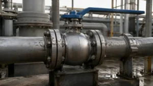
A ball valve contains a drilled ball between two seats. When the valve closes, the solid sides of the ball block the pipeline openings. Fluid may remain in the space around the outside of the ball, between the two seats. This space is called the body cavity.
The cavity may contain:
- Process liquid
- Condensate
- Water left after hydrostatic testing
- Cleaning or flushing fluid
- Refrigerant or liquefied gas
- Oil, grease, or sealant
- A mixture of liquid and vapor
- Fluid leaking through one seat
A closed valve can therefore contain three different pressures:
- Upstream pipeline pressure
- Downstream pipeline pressure
- Body-cavity pressure
These pressures do not have to be equal. For example, a valve may close while both sides are at 50 bar. The downstream pipe is then drained to zero, but the cavity remains close to 50 bar because the seats isolate it from the downstream gauge. If the trapped liquid becomes warmer, cavity pressure may rise above 50 bar.
The final trapped pressure also depends on the operating sequence. While the ball is moving, the cavity may briefly connect with one or both sides of the pipeline. Upstream pressure, downstream pressure, seat design, valve direction, and the timing of depressurization can all affect the pressure left inside the cavity.
A small cavity does not mean a small risk. Even a few hundred milliliters of completely trapped liquid can generate damaging pressure.
Thermal Expansion
Heating a trapped liquid is the most common cause of cavity overpressure.
Most liquids expand as their temperature rises. In an open tank, the liquid level rises. Inside a sealed valve cavity, there may be almost no free space for the added volume.
The liquid can only:
- Compress slightly
- Move a seat
- Compress an O-ring or soft seal
- Stretch the valve body or connected pipe
- Leak through a seat
- Escape through a relief path
If none of these movements provides enough space, pressure rises quickly.
Common heat sources include:
- Direct sunlight
- Steam tracing
- Electric heat tracing
- Nearby hot equipment
- Heat conducted through connected pipe
- Hot process fluid before isolation
- Heat remaining after shutdown
- Cold liquid warming to room temperature
- External fire
The liquid does not need to boil. Ordinary liquid expansion can damage seats, seals, fittings, or the valve body. OSHA has warned that isolated equipment containing liquid can be overpressurized by thermal expansion, causing rupture and loss of containment.[2]
One common case occurs when a valve is filled with cold liquid at night and heated by sunlight the next day. Another occurs when production stops but the steam tracing remains on. The liquid continues to absorb heat even though there is no flow.
For hot systems, the valve rating must be checked at the actual service temperature rather than at room temperature. This is also important when selecting a ball valve for steam or other high-temperature service.
Pressure Rise Data
A simple screening equation for a completely liquid-filled, rigid, leak-free cavity is:
Pressure rise ≈ bulk modulus × volumetric expansion coefficient × temperature rise
The following example uses:
- Liquid bulk modulus: 1.5 GPa
- Volumetric expansion coefficient: 0.0007 per °C
- No gas pocket
- No seat movement or leakage
- No expansion of the valve body
| Temperature Rise | Theoretical Pressure Rise | Pressure Rise in psi |
|---|---|---|
| 5°C | 5.25 MPa / 52.5 bar | About 761 psi |
| 10°C | 10.5 MPa / 105 bar | About 1,523 psi |
| 20°C | 21 MPa / 210 bar | About 3,046 psi |
| 30°C | 31.5 MPa / 315 bar | About 4,569 psi |
These are theoretical screening values, not predictions for a real valve. Actual pressure may be lower because the valve body stretches, seals compress, seats move, or fluid leaks out.
The data still show why a modest temperature rise cannot be ignored. Technical work published through the U.S. Chemical Safety Board also shows that trapped-liquid pressure can become very high while the required thermal relief area remains relatively small.[3]
An accidental gas pocket may reduce the initial pressure rise because gas is compressible. It is not a reliable safeguard. The amount of gas is unknown and may disappear after flushing, hydrotesting, condensation, or further seat leakage.
Expansion Volume Data
Thermal overpressure may require only a small amount of liquid to be released.
A simple estimate is:
Expansion volume ≈ cavity volume × expansion coefficient × temperature rise
The following table uses a volumetric expansion coefficient of 0.0008 per °C and a temperature rise of 30°C.
| Cavity Volume | Added Liquid Volume |
|---|---|
| 0.25 L | 6 mL |
| 0.50 L | 12 mL |
| 1.00 L | 24 mL |
| 2.00 L | 48 mL |
| 5.00 L | 120 mL |
A 1 L cavity heated by 30°C may add only about 24 mL of liquid volume. However, if those 24 mL cannot escape, the cavity pressure can rise sharply.
This is why thermal relief is often described as a small-flow, high-pressure-risk case.
Heating Rate Data
The required thermal relief flow depends on how quickly the liquid becomes warmer.
A simple estimate is:
Expansion flow ≈ cavity volume × expansion coefficient × temperature rise per unit time
The following example uses a 1 L liquid-filled cavity and an expansion coefficient of 0.0008 per °C.
| Heating Rate | Added Volume per Hour | Average Expansion Flow |
|---|---|---|
| 2°C/hour | 1.6 mL/hour | 0.027 mL/min |
| 5°C/hour | 4.0 mL/hour | 0.067 mL/min |
| 10°C/hour | 8.0 mL/hour | 0.133 mL/min |
| 20°C/hour | 16.0 mL/hour | 0.267 mL/min |
These flows are small, but the relief path can still fail if its inlet is blocked, its outlet has excessive backpressure, or the fluid freezes, crystallizes, or polymerizes inside a narrow passage.
Seat Leakage
A seat does not have to leak to the outside of the valve to raise cavity pressure. It may allow process fluid to pass slowly into the cavity while the second seat remains closed.
Consider this condition:
- Upstream pressure: 100 bar
- Downstream pressure: 0 bar
- Cavity initially drained
- Upstream seat leaking
- Downstream seat sealing
Fluid enters through the upstream seat. The cavity pressure gradually moves toward 100 bar. If the trapped liquid later becomes warmer, cavity pressure may rise above the upstream pressure.
This is why pressure may return after a technician bleeds the cavity. Bleeding removes the existing pressure, but it does not stop the seat from leaking again.
Common causes of seat leakage include:
- Particles between the ball and seat
- Scratched ball or seat surfaces
- Damaged PTFE, reinforced PTFE, PEEK, nylon, or elastomer seals
- Corrosion
- Thermal distortion
- Incorrect seat preload
- Low-temperature seal shrinkage
- Frequent operation
- Incorrect assembly after maintenance
A practical ball valve leak diagnosis should separate seat leakage, stem leakage, and body-joint leakage before repairs begin.
Seat Leakage Trend
The table below is an illustrative pressure trend after a cavity has been drained. Temperature remains nearly constant, upstream pressure stays at 100 bar, and downstream pressure remains at zero.
| Time After Bleeding | Upstream Pressure | Cavity Pressure | Downstream Pressure |
|---|---|---|---|
| 0 minutes | 100 bar | 0 bar | 0 bar |
| 10 minutes | 100 bar | 18 bar | 0 bar |
| 20 minutes | 100 bar | 34 bar | 0 bar |
| 40 minutes | 100 bar | 59 bar | 0 bar |
| 60 minutes | 100 bar | 73 bar | 0 bar |
Because the temperature is stable and cavity pressure is moving toward upstream pressure, the upstream seat is the most likely leak path.
This table shows a diagnostic pattern only. It is not a standard leakage rate, and the actual pressure curve depends on cavity volume, seat damage, fluid compressibility, and leak size.
Trapped Line Pressure
A cavity may retain the original pipeline pressure even when no new leakage occurs.
- Both sides of the valve are at 80 bar.
- The valve closes.
- The downstream pipe is depressurized.
- The cavity remains near 80 bar.
- The valve becomes warmer.
- Cavity pressure rises above the original value.
A zero downstream gauge reading does not prove that the valve cavity is at zero pressure. The gauge is outside the downstream seat, while the trapped pressure is between the seats.
Vapor Formation
A trapped liquid may partly turn into vapor when it warms or when pressure changes. This is important for refrigerants, LNG, LPG, ammonia, carbon dioxide, liquid nitrogen, liquid oxygen, and light hydrocarbons.
When cryogenic liquid is isolated, heat enters through the valve body and connected pipe. Part of the liquid vaporizes. The vapor occupies more space and raises cavity pressure.
Simple ideal-gas calculations are not enough for many refrigerants and liquefied gases. Their density, vapor pressure, compressibility, viscosity, and phase can change greatly with temperature and pressure.
NIST REFPROP provides evaluated property models for pure fluids and mixtures in liquid, gas, and supercritical conditions.[4]
Low-temperature valves also need suitable body materials, seats, stem extensions, and relief orientation. These points are covered in this cryogenic ball valve selection guide and the forged cryogenic ball valve range.
Reaction and Fire
Some trapped fluids can react, decompose, polymerize, or release dissolved gas. Examples include reactive monomers, peroxides, contaminated chemicals, water-reactive fluids, and products that continue curing after shutdown.
A small thermal relief valve may handle slow liquid expansion but may be too small for rapid gas generation. The required relief capacity must match the actual pressure source.
Fire is also a separate case. It can cause liquid expansion, boiling, rapid vapor generation, soft-seat failure, seal damage, and external leakage.
A valve that is described as fire-safe does not automatically have enough cavity-relief capacity for a fire. Fire qualification and cavity-overpressure protection must be checked separately.
Floating Ball Valves
A floating ball is held between two seats without upper and lower trunnion supports. Line pressure moves the ball slightly toward the downstream seat, increasing the sealing force.
Some floating-ball valves use flexible seats that can move away from the ball when cavity pressure becomes higher than pressure in the adjacent pipe. Other designs use a drilled ball or an internal equalizing passage.
Do not assume every floating valve is self-relieving. When reviewing a forged soft-seated floating ball valve, confirm:
- Whether automatic cavity relief is provided
- Which side receives the released fluid
- The pressure difference needed to move the seat
- Whether relief works in liquid service
- Whether installation is directional
- Whether relief works across the full temperature range
- Whether deposits can restrict seat movement
Trunnion Ball Valves
A trunnion-mounted ball is supported at the top and bottom. The ball rotates but does not move downstream like a floating ball. Spring-loaded seat rings move toward or away from the ball.
The basic seat-force relationship is:
Seat force = pressure × effective area
Pressure acts on different ring-shaped areas of the seat assembly. The resulting force determines whether the seat moves toward the ball or away from it.
This is the main difference between single-piston-effect and double-piston-effect seats. A trunnion-mounted ball valve should therefore be selected from its seat drawing and pressure-direction diagram, not only from its size and pressure class.
SPE Seats
SPE means single-piston effect.
When line pressure is higher than cavity pressure, the seat is pushed against the ball and seals. When cavity pressure becomes sufficiently higher than pressure in the adjacent pipe, the net force can reverse. The seat moves away from the ball and releases fluid into the lower-pressure side.
An SPE seat can provide automatic internal cavity relief, but only when:
- The seat is free to move
- The required pressure difference is reached
- A lower-pressure receiving side is available
- The relief route is not blocked
Relief may be delayed or prevented when:
- Both pipeline sides are highly pressurized
- The receiving pipe section is isolated
- Deposits restrict seat movement
- Low temperature increases seal friction
- The seat is damaged or distorted
- The valve is installed in the wrong direction
There is no universal SPE opening pressure. Seat area, spring load, seal friction, temperature, and manufacturing tolerances all affect the required differential pressure.
SPE Pressure Difference
The available pressure difference is the cavity pressure minus the receiving-side pressure.
| Cavity Pressure | Receiving-Side Pressure | Available Difference | Relief Condition |
|---|---|---|---|
| 110 bar | 108 bar | 2 bar | The pressure difference may be too small to move the seat. |
| 110 bar | 100 bar | 10 bar | The seat has more force available to open. |
| 110 bar | 90 bar | 20 bar | Internal relief is more likely if the seat is designed to open below this difference. |
The table does not define a standard opening pressure. The actual value must come from the valve manufacturer.
DPE Seats
DPE means double-piston effect.
A DPE seat is pushed toward the ball when pressure acts from either the pipeline side or the cavity side. This provides a second sealing barrier if the first seat leaks.
The same action can trap cavity pressure. Instead of moving away from the ball, the DPE seat may seal more tightly as cavity pressure rises.
A valve with DPE seats on both sides normally needs another relief method, such as:
- A body-mounted relief valve
- An external thermal relief valve
- A pressure-return line
- A manufacturer-designed cavity passage
DPE is not an unsafe design. It is useful when strong bidirectional isolation is required. The risk occurs when liquid can be trapped between two DPE seats without automatic relief.
Mixed Seat Designs
Some valves use SPE on one side and DPE on the other.
The SPE seat provides the normal cavity-relief path. The DPE seat provides additional isolation.
These valves are often directional. Reversing the valve may change:
- Which seat seals first
- Where cavity pressure is released
- Whether automatic relief remains available
- Whether the intended isolation function still works
The valve drawing, nameplate, and piping documents should clearly show the required direction.
DBB and DIB
DBB means double block and bleed. DIB means double isolation and bleed.
These terms describe isolation performance. They do not prove that the cavity automatically relieves thermal pressure.
A manual bleed valve works only when someone opens it. If it remains closed, the cavity can still become overpressurized.
Ask four questions:
- Which seat blocks pressure from each direction?
- Can cavity pressure move either seat away from the ball?
- Where does the released fluid go?
- What happens if the receiving side is isolated?
An integrated DBB compact manifold can reduce the number of separate valve bodies and pipe joints, but its bleed and cavity-relief functions still need to be checked from the actual seat design.
Vented Balls
A vented ball has a small drilled hole connecting the trapped space to one pipeline side. This gives expanding liquid a direct return path.
The valve often becomes directional. If installed backward, the relief hole may face the wrong side or become unavailable in the required isolation condition.
The hole may be restricted by:
- Solid particles
- Ice
- Polymer deposits
- Crystals
- Scale
- Corrosion products
- Grease or coating material
Partial blockage may be enough to reduce relief capacity. The manufacturer should state which space the hole connects, its direction, its size, and how it can be inspected.
Do not drill a ball in the field without approved engineering documents. Drilling can change sealing direction, cavity behavior, strength, flow performance, and product certification.
What Pressure Can Damage
A typical failure sequence is:
- Cavity pressure rises.
- Seat and seal loads increase.
- Operating torque rises.
- Soft seats or O-rings deform.
- Internal or external leakage starts.
- Fittings, joints, and the valve body remain exposed to pressure.
Possible damage includes:
- Extruded or torn soft seats
- Deformed seat carriers
- Damaged O-rings
- Stem-packing leakage
- High breakaway torque
- Actuator overload
- Body-joint leakage
- Failed vent or drain fittings
- Valve-body rupture in a severe case
Installing a larger actuator does not remove cavity pressure. It may transfer the overload to the stem, coupling, gearbox, ball, or seat.
Pressure limits must be checked at the actual metal temperature. ASME B16.34 covers pressure-temperature ratings, dimensions, materials, testing, and marking for applicable valves.[5]
For high-temperature or abrasive service, a forged metal-seated ball valve may be more suitable than a standard soft-seated design. Metal seats do not remove the need for cavity relief.
Thermal Pressure Trend
The following table shows an illustrative field trend. It is not a pressure prediction for a specific fluid or valve.
| Time | Valve Temperature | Upstream Pressure | Cavity Pressure | Downstream Pressure |
|---|---|---|---|---|
| 08:00 | 20°C | 40 bar | 40 bar | 0 bar |
| 10:00 | 28°C | 40 bar | 58 bar | 0 bar |
| 12:00 | 36°C | 40 bar | 76 bar | 0 bar |
| 14:00 | 43°C | 40 bar | 91 bar | 0 bar |
Upstream and downstream pressures remain stable while cavity pressure rises with temperature. This pattern points more strongly to thermal expansion than to a simple seat leak.
How to Identify the Cause
Collect the following information before making changes:
- Valve manufacturer and model
- Serial number
- Valve size and pressure class
- Sectional drawing
- Ball type
- Seat material and seat effect
- Flow arrow
- Relief-device details
- Upstream pressure
- Downstream pressure
- Cavity pressure
- Fluid and valve-body temperature
- Heat-tracing condition
The pressure pattern often points to the cause:
- Pressure rises with temperature: thermal expansion or vaporization is likely.
- Pressure approaches upstream pressure: check the upstream seat.
- Pressure approaches downstream pressure: check the downstream seat.
- Pressure rises above both sides: trapped-liquid expansion, vaporization, or gas generation is likely.
- Pressure returns immediately after bleeding: check for a large seat leak or direct process connection.
- Pressure returns slowly at stable temperature: a small seat leak is possible.
Record pressure and temperature together over time. A trend is more useful than a single reading.
Safe Field Checks
A cavity gauge is useful only when its connection is open and clear.
A zero reading may be false if:
- The root valve is closed
- The pressure passage is plugged
- Liquid is frozen
- The gauge is damaged
- The gauge range is unsuitable
Do not:
- Loosen a plug or fitting to check for pressure
- Open a manual vent without a safe discharge route
- Force a locked valve with a larger actuator
- Remove a gauge or relief valve while pressure may remain
- Perform an improvised high-pressure cavity test
Stop operating the valve if pressure rises rapidly, exceeds the expected range, repeatedly returns after depressurization, causes external leakage, or overloads the actuator.
Relief Methods
The main cavity-protection methods are:
| Relief Method | How It Works | Main Limitation |
|---|---|---|
| Self-relieving seat | The seat moves away from the ball when the designed pressure difference is reached. | Needs a free-moving seat and an available lower-pressure side. |
| Vented ball | A drilled hole keeps the cavity connected to one pipeline side. | Usually directional and vulnerable to blockage. |
| Body relief valve | A spring-loaded relief device connects directly to the body cavity. | The inlet, root valve, and outlet route must remain open. |
| External thermal relief valve | Protects the cavity and an isolated pipe section through an external connection. | The connection must communicate with every trapped volume. |
A manual bleed connection is useful for testing, draining, and maintenance. It is not automatic overpressure protection when closed.
Shell testing, seat testing, operating checks, and cavity-relief verification examine different parts of valve performance. See the related guide to API 6D ball valve testing.
Set Pressure
Do not select a relief setting from normal line pressure alone.
Check the allowable pressure of:
- The valve body at maximum temperature
- Body joints and bolting
- Seats and seals
- Stem packing
- Vent and drain valves
- Pressure gauges
- Instrument tubing and fittings
- Connected piping
The lowest-rated component controls the safe limit.
The relief setting must be:
- Above the highest expected normal pressure
- Below the allowable pressure of the protected equipment
- Adjusted for inlet pressure loss
- Adjusted for outlet backpressure
- Checked for relief-device tolerance
- Checked for pressure accumulation while relieving
The API 6D limit of 33% differential pressure above the valve pressure rating applies only within the conditions stated by the standard. It is not a universal setting for every valve, fluid, or piping system.[6]
Relief Capacity
A relief device must pass enough fluid to prevent pressure from continuing to rise.
For ordinary liquid expansion, the required flow may be very small. However, the following conditions may require much more capacity:
- External fire
- Rapid vaporization
- Chemical decomposition
- Polymerization
- Full pump flow entering the trapped section
- Compressor pressure
- A blocked process outlet
Do not assume that a small thermal relief valve also protects against fire, reaction, or full process flow.
Where the Fluid Should Go
A relief device is useful only if its outlet remains open and leads to a safe location.
Possible destinations include:
- Upstream process pipe
- Downstream process pipe
- Closed drain
- Flare system
- Recovery vessel
- Low-pressure process return
Before selecting the outlet, check whether:
- A valve can isolate the receiving line
- A check valve blocks reverse flow
- The receiving pressure is too high
- The line can freeze or plug
- Liquid can collect in a low point
- Backpressure can prevent relief
- The released fluid can contaminate another process
- The discharge can expose personnel
OSHA requirements for ammonia piping require hydrostatic relief where liquid may be trapped between closures and state that the relief flow must not be restricted.[7] These requirements apply to ammonia service, but the same basic lesson is useful elsewhere: the outlet must remain open and must not create a second hazard.
Worked DPE Example
Consider a trunnion-mounted ball valve with:
- Cavity volume: 1.2 L
- Fluid: liquid hydrocarbon
- Initial pressure: 60 bar
- Expansion coefficient: 0.0009 per °C
- Isolation temperature: 20°C
- Maximum expected temperature: 65°C
- Seat arrangement: DPE/DPE
- Both pipeline sides capable of being isolated
The temperature rise is:
65 − 20 = 45°C
The estimated expansion volume is:
1.2 × 0.0009 × 45 = 0.0486 L
This equals 48.6 mL.
The added volume is small, but the two DPE seats may prevent it from escaping. Because the liquid is difficult to compress, cavity pressure can rise sharply.
A suitable design review should:
- Confirm that the DPE/DPE seats do not self-relieve.
- Provide a direct relief connection to the cavity.
- Route the fluid to a closed or safe receiving system.
- Confirm that the outlet remains available when both line sides are isolated.
- Set the relief pressure below the allowable pressure of the weakest component at 65°C.
- Include outlet backpressure and pressure accumulation.
- Evaluate fire and rapid vaporization separately.
Special Services
Cryogenic fluids: Check ball vent direction, extended stem orientation, ice blockage, low-temperature materials, and liquid trapped inside the ball bore or small fittings.
Refrigerants and carbon dioxide: Use reliable property data because the medium may move between liquid, vapor, two-phase, dense-fluid, and supercritical states.
Hot oil: Check heat soak, coke deposits, high viscosity, blocked passages, and tracing that remains on after shutdown.
Polymerizing or crystallizing fluids: Reduce dead space where practical and provide cleaning access because small holes and tubes can gradually become blocked.
Corrosive or sour fluids: Confirm the material of the body, seats, springs, stem seals, cavity fittings, and relief tubing. The side-entry ball valve material guide compares common carbon-steel, stainless-steel, and duplex options.
Selection Checklist
Before ordering the valve, obtain written answers to these questions:
- Can liquid become trapped in the open or closed position?
- Is the ball floating or trunnion-mounted?
- Is each seat SPE or DPE?
- Does the valve relieve automatically?
- At what pressure difference does relief begin?
- Which side receives the released fluid?
- Is the valve directional?
- Does the ball contain a vent hole?
- Can the relief passage freeze, plug, or collect deposits?
- Is an external thermal relief valve required?
- What is the pressure rating at maximum temperature?
- Can the receiving side be isolated?
- How is the relief function tested?
- What changes after the ball, seats, or seals are replaced?
ISO 14313:2025 covers the design, manufacture, materials, testing, documentation, and process control of pipeline valves in ASME Classes 150, 300, 600, 900, 1500, and 2500. It supplements API 6D, 25th Edition.[8]
Maintenance
Routine inspection should include:
- Relief-valve setting and reseating
- Correct root-valve position
- Blocked or partly blocked vent holes
- Relief-line backpressure
- Frozen liquid or collected condensate
- Polymer, crystal, scale, or corrosion deposits
- Seat leakage trends
- Flow-arrow visibility
- Valve and ball orientation
- Unapproved changes to relief piping
- Heat-tracing condition
After replacing the ball, seats, seals, or cavity fittings, verify the relief function again.
Changing from SPE to DPE seats can remove the original internal relief path. Replacing a vented ball with an unvented ball, or installing the ball in the wrong direction, can have the same effect.
Maintenance records should include the valve serial number, seat arrangement, relief-device identification, set pressure, test date, observed pressure and temperature, replaced parts, and any changes to the discharge pipe.
Conclusion
A closed ball valve can trap liquid even when the downstream gauge reads zero. Under ideal rigid conditions, a 10°C temperature rise can theoretically add about 105 bar, while a 1 L cavity heated by 30°C may need to release only 24 mL. This combination of high pressure and low flow makes cavity overpressure easy to underestimate. Confirm whether the valve uses SPE, DPE, mixed seats, or a vented ball. Check the pressure rating at maximum temperature, the relief opening pressure, outlet backpressure, and the receiving route. Recheck the relief function after every seat, ball, seal, or piping change.







