
The decision should be based on valve size, body shape, material, operating temperature, pressure cycles, inspection scope, repair limits, documentation, and delivery risk. A fair comparison requires forged and cast suppliers to quote the same technical requirements.
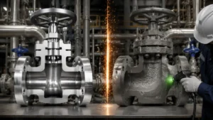
Quick Comparison
A forged body starts as solid steel that is heated, shaped, heat treated, and machined. A cast body starts as molten steel poured into a mold.
| Item | Forged body | Cast body |
|---|---|---|
| Best starting point | Small, compact, high-pressure valves | Large valves with complex passages |
| Internal passage | Mainly machined from solid metal | Mainly formed by mold cores |
| Main internal concerns | Laps, seams, bursts, inclusions, and centerline indications | Shrinkage, gas porosity, inclusions, hot tears, and cold shuts |
| Common internal test | Ultrasonic testing, or UT | Radiographic testing, or RT |
| Repair welding | Less common | More common when permitted |
| Machining volume | Usually higher | Usually lower |
| Large-size cost | Can increase sharply | Usually lower |
| Main schedule risk | Raw-forging availability and long machining time | RT rejection, repair, repeat heat treatment, or recasting |
Forging does not guarantee a defect-free body. Casting does not automatically mean low quality. The result depends on the steel source, manufacturing process, heat treatment, inspection, and repair control.
Buyers can compare the construction of a forged high-pressure ball valve with a cast steel ball valve, but both quotations must use the same material, design standard, NDE, testing, and documentation requirements.
What Class 1500+ Means
Class 1500 does not mean that a valve can always operate at exactly 1,500 psi. The class number is a pressure-rating group. Actual allowable pressure depends on body material and operating temperature.
A complete valve request should state:
- Design pressure
- Design temperature
- Valve size and type
- Body material
- Fluid and service condition
- Pressure class
- End connection
- Applicable valve standard
- Standard Class or Special Class construction
ASME B16.34 covers pressure-temperature ratings, materials, dimensions, nondestructive examination, testing, and marking for cast, forged, and fabricated valves. The purchase order should name the edition that applies to the project.[1]
For pipeline ball valves, the RFQ should also define the applicable API 6D valve specifications, including bore, body design, pressure class, material, end connection, seat arrangement, and testing.
Standard Class vs Special Class
Pressure class and construction category are separate items. A valve may be Class 1500 Standard Class or Class 1500 Special Class.
Special Class is not simply a Standard Class valve with an extra RT or UT report. It is a separate rating route under ASME B16.34. The manufacturer must meet all applicable material, manufacturing, examination, testing, and marking requirements in the specified edition.
The datasheet should clearly state one of the following:
- Class 1500 Standard Class
- Class 1500 Special Class
- Class 2500 Standard Class
- Class 2500 Special Class
A supplier should not mark a valve as Special Class only because additional NDE was performed.
Common Body Materials
| Service | Forged material examples | Cast material examples |
|---|---|---|
| Carbon steel | ASTM A105 | ASTM A216 WCB or WCC |
| Low-temperature service | ASTM A350 LF2 | ASTM A352 LCB or LCC |
| Alloy steel | ASTM A182 F11, F22, or F91 | ASTM A217 grades selected for the service |
| Austenitic stainless steel | ASTM A182 F304 or F316 | ASTM A351 CF8M or CF3M |
| Duplex stainless steel | ASTM A182 F51, F53, or F55 | ASTM A995 pressure-containing casting grades |
ASTM A105 covers forged carbon steel piping components, including valves, for ambient and higher-temperature pressure service. Extra examinations do not apply automatically unless they are required by the product standard or specified in the order.[2]
ASTM A350 covers carbon and low-alloy steel forgings intended mainly for low-temperature service and requiring notch-toughness testing.[3]
ASTM A182 covers forged or rolled alloy and stainless steel flanges, fittings, valves, and valve parts for pressure and high-temperature service.[4]
ASTM A216 covers carbon steel castings for valves and other pressure-containing parts. It includes WCA, WCB, and WCC grades.[5]
ASTM A352 covers ferritic and martensitic steel castings for valves and other pressure-containing parts intended mainly for low-temperature service.[6]
ASTM A703 provides common requirements for pressure-containing steel castings. The individual material specification still controls the grade-specific chemistry, heat treatment, mechanical properties, and testing.[7]
The material grade alone is not enough. The buyer should also check:
- Heat-treatment condition
- Chemical composition
- Tensile and yield results
- Impact-test temperature and absorbed energy
- Hardness
- Positive material identification
- Heat-number traceability
- Repair-weld records
- Final NDE reports
For further comparison, see this guide to carbon steel, stainless steel, and duplex ball valve materials.
Forging Defects
| Indication | How it forms | Useful inspection |
|---|---|---|
| Lap | A surface layer folds over without fully bonding | MT or PT after machining |
| Seam | A billet defect becomes stretched during forging | MT, PT, or UT |
| Burst | Internal cracking caused by poor temperature or excessive deformation | UT |
| Inclusion | Nonmetallic material remains from steelmaking | UT |
| Centerline indication | Segregation, shrinkage, or inclusions remain near the billet center | UT |
Adequate forging reduction can improve the steel structure and may close some internal voids. It does not remove every inclusion, crack, or segregation zone. UT is still needed when required by the standard or purchase order.
The supplier should identify the starting material, forging route, heat treatment, and UT stage. This article on how forged ball valves are made explains the main manufacturing steps.
Bar Stock Bodies
A body machined from bar stock is not the same as a shaped forging. However, bar stock is not automatically unacceptable.
Its suitability depends on:
- The applicable valve and material standards
- Body size
- Location of the bar centerline in the finished body
- Steelmaking and reduction history
- UT access and coverage
- Purchaser restrictions
The purchase order should state whether bar stock is allowed, limited to certain sizes, subject to extra UT, or prohibited for pressure-containing bodies.
Casting Defects
| Indication | How it forms | Main concern |
|---|---|---|
| Shrinkage | A solidifying section does not receive enough liquid metal | Internal cavities or connected networks |
| Gas porosity | Gas becomes trapped during solidification | Rounded or grouped cavities |
| Inclusion | Slag, oxide, sand, or another material becomes trapped | Reduced sound metal |
| Hot tear | The partly solid casting cracks during contraction | Crack-like indication |
| Cold shut | Two streams of molten steel meet without fully joining | Linear, crack-like indication |
Shrinkage is more likely around flange hubs, seat pockets, trunnion supports, drain bosses, body-to-bonnet transitions, and other thick sections.
Defect shape and location matter. Scattered round pores in a thick, low-stress area are not the same as linear shrinkage beside a seat pocket or flange hub.
Critical Body Areas
RT and other inspections should pay special attention to:
- Body-to-bonnet necks
- Flange hubs
- Butt-weld ends
- Seat pockets
- Stem and shaft openings
- Trunnion supports
- Drain and vent bosses
- Thick-to-thin transitions
- Minimum-wall areas
- Repair-weld locations
An NDE indication is not automatically a rejectable defect. It becomes rejectable when it exceeds the specified acceptance limit or belongs to a prohibited category.
As a simple example, an RT map for a trunnion-mounted cast body may divide the pressure boundary into six main zones:
- Inlet flange or weld-end hub
- Outlet flange or weld-end hub
- Left seat pocket
- Right seat pocket
- Stem or bonnet area
- Lower body cavity
Six zones do not mean six images. A zone may need several exposures when walls overlap or thickness changes sharply. This is an example, not a standard RT layout.
When RT Is Required
A Class 1500 or Class 2500 marking alone is not a complete RT requirement.
The inspection scope may come from:
- ASME B16.34
- The applicable API valve standard
- The body material specification
- The piping code
- The project valve specification
- The purchase order
- Applicable legal requirements
Depending on valve type, the product standard may include API 600, API 602, API 608, or API 6D. The order should state the exact edition and applicable addenda or errata. API publishes official corrections and updates for its standards.[8]
The contract should also explain which document controls if two requirements conflict. Document priority cannot be used to ignore a mandatory minimum requirement in an applicable standard.
What 100% RT Means
“100% RT” is too vague unless the purchase order defines what must be covered.
It may mean:
- All areas named in the purchase specification
- All pressure-containing areas that can be practically radiographed
- All areas shown on an approved RT map
- The complete body using RT plus approved UT where RT is not practical
These meanings are not equal. A valve body contains curved passages, overlapping walls, bosses, seat pockets, and large thickness changes. Some areas cannot be examined with the same sensitivity as a flat casting.
An RT map should show:
- Exposure number
- Source position
- Film or detector position
- Radiation direction
- Area covered
- Section thickness
- Overlap between exposures
- Areas with limited sensitivity
- Any proposed UT substitution
Where purchaser approval is required, the RT map should be approved before the examination begins.
RT Method and Acceptance
The RT method and acceptance criteria are separate requirements.
The method explains how the image is produced. It covers the radiation source, image quality indicator, exposure geometry, film or detector, processing, image quality, and identification.
The acceptance criteria explain which indications may remain in the final body.
ASME BPVC Section V covers nondestructive examination methods. The applicable construction standard or purchase specification must still define the inspection extent and final acceptance rules.[9]
Radiographic testing uses X-rays or gamma rays to produce an image of the internal condition of a component.[10]
RT Thickness Ranges
The correct reference-image standard depends on casting thickness and whether the inspection uses film or a digital system.
| RT format | Reference standard | Steel casting thickness |
|---|---|---|
| Film | ASTM E446 | Up to 2 in. or 50.8 mm |
| Film | ASTM E186 | 2 in. to less than 4.5 in., or 50.8 to 114 mm |
| Film | ASTM E280 | 4.5 to 12 in., or 114 to 305 mm |
| Digital | ASTM E2868 | Up to 2 in. or 50.8 mm |
| Digital | ASTM E3030 | 2 in. to less than 4.5 in., or 50.8 to 114 mm |
ASTM E446 provides film reference radiographs for steel castings up to 2 in. or 50.8 mm thick.[11]
ASTM E186 applies to film radiography of steel castings from 2 in. to less than 4.5 in., or 50.8 to 114 mm thick.[12]
ASTM E280 applies to film radiography of steel casting sections from 4.5 to 12 in., or 114 to 305 mm thick.[13]
ASTM E2868 provides digital reference images for steel castings up to 2 in. or 50.8 mm thick.[14]
ASTM E3030 provides digital reference images for steel castings from 2 in. to less than 4.5 in., or 50.8 to 114 mm thick. It should not be extended automatically to thicker sections.[15]
RT Acceptance Levels
ASTM reference images help inspectors identify casting indication types and compare their relative severity. They do not provide one automatic acceptance limit for every valve.
The purchase order must state the permitted severity for each relevant category. It should not say only “RT according to ASTM E446.”
| Indication | Illustrative project limit |
|---|---|
| Gas porosity | Maximum Level 2 |
| Sand or slag inclusion | Maximum Level 2 |
| Linear shrinkage | Maximum Level 1 |
| Feathery shrinkage | Maximum Level 2 |
| Sponge shrinkage | Maximum Level 2 |
| Crack | Not allowed to remain in the accepted body |
| Hot tear | Not allowed to remain in the accepted body |
| Cold shut | Not allowed to remain in the accepted body |
The limits above are only examples. They are not default ASTM or ASME acceptance criteria. The engineer must select the final limits according to body location, wall thickness, valve design, service conditions, and project risk.
“Not allowed” means the indication cannot remain in the accepted body. Whether the affected area may be removed and repair welded is a separate contract decision.
Film vs Digital RT
Film and digital RT should not automatically use the same reference images.
A digital RT requirement should state:
- Original image format
- Image resolution
- Image quality checks
- Permitted image processing
- Review-monitor requirements
- File naming and traceability
- Retention period
- Purchaser access to original files
A screenshot placed in a PDF is not the same as the original digital RT file.
RT Limitations
RT is useful for gas cavities, shrinkage, inclusions, and other indications that create a clear change in material thickness or density.
RT may be less effective for:
- Tight cracks
- Thin, flat indications
- Defects aligned poorly with the radiation beam
- Areas hidden by overlapping walls
- Very thick sections
- Areas with poor source access
Passing RT does not prove that the body is completely free from every possible defect.
UT for Forgings
Ultrasonic testing uses high-frequency sound waves and analyzes returning echoes to locate internal indications.[16]
UT is often more practical for thick forgings because it can inspect many sections from one accessible surface. It can also detect flat indications when the sound beam reaches them at a suitable angle.
A requirement that says only “100% UT” is incomplete. It should define:
- Inspection standard
- Scan surfaces
- Scan directions
- Coverage
- Calibration method
- Probe type and frequency
- Recording level
- Acceptance level
- Inspection stage
- Report requirements
ASTM A388/A388M covers pulse-echo ultrasonic examination of steel forgings. The order must identify the required quality level and any purchaser-specific requirements.[17]
| Production stage | Typical inspection |
|---|---|
| Raw forging | Visual and dimensional inspection |
| After heat treatment | UT, hardness, and material verification |
| After rough machining | MT or PT on exposed critical areas |
| After final machining | Final MT or PT where specified |
| After assembly | Shell, seat, and functional testing |
Surface Inspection
RT and UT do not replace surface inspection.
Magnetic-particle testing, or MT, is used on magnetic materials such as carbon and low-alloy steel. It can find surface and some near-surface cracks, laps, and seams.
Liquid-penetrant testing, or PT, finds indications open to a clean, nonporous surface. It is commonly used on austenitic stainless steel and other nonmagnetic alloys.
Useful inspection stages include:
- After rough machining
- After defect removal
- After repair welding
- After required heat treatment
- After final machining of critical areas
ASNT identifies RT, UT, MT, and PT as separate NDT methods with different uses and limits.[18]
Repair Welding
Repair welding is common in steel casting production. A repaired casting is not automatically unacceptable, but the repair must be controlled and recorded.
A proper repair process should contain at least these 10 recorded steps:
- Record the original indication and its location.
- Remove the affected metal by grinding or machining.
- Use MT or PT to confirm complete removal.
- Measure excavation depth, length, width, and remaining wall.
- Obtain purchaser approval when the agreed limit is exceeded.
- Use an approved welding procedure and qualified personnel.
- Control preheat and interpass temperature.
- Perform required heat treatment.
- Repeat surface and internal inspection.
- Add the repair records to the manufacturing data book.
The purchase order should define a major repair using measurable limits such as:
- Excavation depth in millimeters
- Percentage of local wall thickness removed
- Total repair area in square millimeters or square centimeters
- Location inside a critical zone
- Need for another heat-treatment cycle
- Repair after final heat treatment
- Repeated repair at the same location
A complete ban on all repairs can increase cost and delivery time. Unlimited repair is also poor practice. The better approach is to define minor repairs, major repairs, prohibited areas, approval points, and maximum repair cycles.
Heat Treatment
Heat treatment affects strength, toughness, hardness, corrosion resistance, and dimensions.
The manufacturing record should include:
- Furnace identification and calibration
- Thermocouple locations
- Heating rate
- Holding temperature
- Holding time
- Cooling method
- Number of heat-treatment cycles
A major repair after final heat treatment may require another cycle. Repeated cycles can affect hardness, mechanical properties, dimensions, and microstructure.
Pressure Testing
A hydrostatic shell test checks whether the assembled valve holds pressure during a specified test. It does not prove that the body contains no internal indications.
A body may pass a short factory test while still containing an indication affected later by:
- Pressure cycling
- Temperature changes
- Vibration
- External piping loads
- Hydrogen exposure
- Corrosion or erosion
Pressure testing and NDE have different purposes. NDE checks the material condition. Pressure testing checks leakage and pressure-boundary performance during the test.
This guide explains the main API 6D shell, seat, and functional tests.
What Changes the Cost
There is no fixed percentage by which a forged body costs more than a cast body.
The price changes with:
- Valve size and type
- Pressure class
- Material grade
- Body shape
- Order quantity
- Raw-material availability
- Tooling
- Machining time
- NDE scope
- Acceptance limits
- Repair restrictions
- Third-party inspection
- Documentation
- Delivery schedule
Forged bodies usually need more machining because the internal passage must be cut from solid metal. The cost effect becomes larger for stainless steel, duplex steel, nickel alloy, and large Class 2500 bodies.
Cast bodies normally use material more efficiently, but the quotation may need to include RT, repair welding, repeat heat treatment, repeat RT, or complete recasting.
Material Use Example
The following figures are an illustrative calculation, not an industry average.
| Example | Starting weight | Finished body weight | Weight removed or lost |
|---|---|---|---|
| Forged body | 300 kg | 180 kg | 120 kg, or 40% |
| Near-net-shape cast body | 210 kg | 180 kg | 30 kg, or about 14% |
In this example, the forging requires four times as much metal removal as the casting. The difference becomes expensive when the removed material is stainless steel, duplex steel, or nickel alloy.
The casting still has other costs, including patterns, cores, risers, cleaning, heat treatment, RT, and possible repair.
Cost Calculation Example
The figures below are hypothetical cost units. They show the calculation method and are not market prices or supplier averages.
| Cost item | Small forged body | Small cast body | Large forged body | Large cast body |
|---|---|---|---|---|
| Body material and forming | 100 | 82 | 155 | 100 |
| Machining | 20 | 12 | 45 | 18 |
| Volumetric NDE | 5 | 9 | 8 | 12 |
| Expected repair cost | 1 | 8 | 2 | 10 |
| Documentation | 3 | 4 | 4 | 5 |
| Total | 129 | 115 | 214 | 145 |
In the small-body example, the forged option is about 12% higher than the cast option. A standardized forging may still be preferred because it can reduce repair and delivery risk.
In the large-body example, the forged option is about 48% higher. Most of the difference comes from raw material and machining rather than UT.
Small-Body Cost Breakdown
The same small-body example can be shown as a percentage of total cost:
| Cost item | Forged share | Cast share |
|---|---|---|
| Body material and forming | 77.5% | 71.3% |
| Machining | 15.5% | 10.4% |
| Volumetric NDE | 3.9% | 7.8% |
| Expected repair | 0.8% | 7.0% |
| Documentation | 2.3% | 3.5% |
This example shows why a cheaper cast blank does not always produce a much cheaper finished valve. RT and expected repair account for 14.8% of the illustrative cast-body total, compared with 4.7% for UT and repair on the forged body.
Selection by Size
| Valve size | Practical starting choice | Main reason |
|---|---|---|
| NPS 2 and smaller | Forged | Standard blanks are common and machining is manageable |
| NPS 3 to NPS 6 | Compare both routes | Valve type, material, and body shape control the result |
| NPS 8 and larger | Cast often has a cost advantage | Large forgings require more material and machining |
This is a purchasing starting point, not a code rule. A simple large split-body ball valve may still use forged parts, while a smaller globe or check valve may favor casting because of its internal shape.
For larger ball valves, the choice between trunnion-mounted and floating construction also changes body shape, seat load, operating torque, and cost.
Data to Request from Suppliers
A useful RFQ should ask for measurable information, not general claims such as “premium forging” or “100% inspected.”
| RFQ item | Required supplier data |
|---|---|
| Body route | Cast, shaped forging, bar-machined, or fabricated |
| Material | Exact ASTM grade, heat number, and heat-treatment condition |
| RT coverage | Percentage and exact body zones |
| UT coverage | Scan surfaces, directions, calibration, and acceptance level |
| Repair depth | Millimeters and percentage of local wall thickness |
| Repair area | Square millimeters or square centimeters |
| Heat treatment | Temperature, holding time, cooling method, and cycle count |
| Impact testing | Test temperature, specimen orientation, and absorbed energy |
| Hardness | Specified limit and measured range |
| Pressure testing | Pressure, medium, hold time, and leakage result |
| Delivery | Raw-material, machining, NDE, assembly, and final-test dates |
| Technical deviations | Complete list of exceptions to the RFQ |
The final document package should connect each valve tag and serial number to its material, heat-treatment, NDE, repair, and pressure-test records. This valve manufacturing data book guide explains how to organize that evidence.
Purchase Wording
Valve bodies shall comply with the contract-specified edition of ASME B16.34 and the applicable product and material standards. The supplier shall identify whether each pressure-containing body is cast, shaped forged, machined from bar, or fabricated. For cast bodies, the supplier shall provide an RT coverage map where required. The procedure shall identify coverage, examination stage, technique, applicable reference-image standard, acceptance levels, areas with limited access, and proposed UT substitution. Major weld repairs require purchaser approval. Repaired areas shall receive final surface and internal examination after required heat treatment. Original and final NDE records, repair maps, heat-treatment charts, material certificates, and pressure-test reports shall be included in the manufacturing data book.
For forged bodies, replace the RT requirement with a detailed UT requirement covering scan directions, calibration, recording level, acceptance limits, inspection stage, and bar-stock restrictions.
Conclusion
For Class 1500+ valves, forged bodies are normally the safer starting choice for compact sizes, while cast bodies usually become more economical as size and passage complexity increase. Do not specify “100% RT” without defining the body zones, technique, thickness-based reference standard, acceptance levels, and repair rules. ASTM film reference ranges run from E446 below 50.8 mm to E280 at 114–305 mm. In the illustrative cost model, the forged premium was about 12% for a small body and 48% for a large body. Compare identical materials, NDE, testing, records, and delivery terms before awarding the order.







