
Across the 22 refining and coal-chemical projects we tracked between 2024 and 2025, the specification debate between flanged-end and butt-welded ball valves showed up on virtually every P&ID review meeting.
Flanged ends cut disassembly time by 60%~80%, but annual leak rates run 0.3%~0.8% per unit in our internal service records. Welded ends remove the bolted end-connection leak path, but usually consume 8~14 additional hours per replacement because of pipe cutting, bevel preparation, re-welding, inspection, and possible heat treatment.
First-cost spreads between the two usually land in the 25%~45% band. We pulled the records from 80+ API 6D Class 150~600 ball valves we delivered, pressure-tested, and serviced over the past 3 years, and broke the differences into three decision dimensions: leak path, installation cost, and maintenance burden, so process engineers and procurement teams have a usable selection basis[1].
The real decision is not whether flanged or welded ends are “better.” The correct question is which connection fits the hazard level, maintenance frequency, shutdown cost, and piping layout of this specific line.
| Selection Factor | Flanged Ends | Welded Ends | Mixed Configuration |
|---|---|---|---|
| Best-fit position | Maintenance-intensive valves, bypasses, drains, samples, and instrument interfaces | Hazardous, low-maintenance, high-containment mainline sections | Lines that contain both hazardous sections and valves requiring access |
| Main advantage | Fast disassembly and lower turnaround workload | Removes the bolted flange-gasket leak path | Balances leak-path reduction and maintenance access |
| Main burden | Gasket, bolt preload, and flange-face leakage risk | Higher welding, NDE, PWHT, and cut-out maintenance cost | Higher design coordination and boundary-valve planning |
| Typical cost driver | Gasket replacement, re-torque, pressure test, and leak response | Welding labor, NDE, PWHT, purging, cutting, and shutdown loss | Correct flange placement, DBB isolation, and 15-year lifecycle planning |
The data range in this article mainly covers API 6D ball valves used in refining, coal-chemical, ethylene, hydrocarbon, sour-water, hydrogen-containing, and high-temperature utility-related services.
The numbers are not intended to replace the owner’s piping specification or project design code. They are used to show the practical selection logic behind end connections: flanged ends are easier to remove, welded ends remove one major removable leak path, and mixed configurations are often used when one line contains both hazardous sections and maintenance-intensive sections.
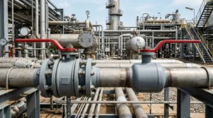
For readers from procurement or project management teams, the key point is that the cheaper valve is not always the lower-cost valve.
End-connection selection affects valve price, gasket replacement, site welding, non-destructive examination, post-weld heat treatment, shutdown duration, leak response, and future turnaround planning.
Flanged Valves
Disassembly Convenience
The defining advantage of flanged ball valves is bolted-joint disassembly.
With 4 to 16 studs and a spiral-wound or ring-joint gasket, the entire valve can be unbolted from the line in 1.5~2.5 hours for a typical Class 300 NPS 4 unit, compared with 8~14 hours for a welded valve that requires cutting, beveling, and possible post-weld heat treatment depending on material, wall thickness, and project requirements[2].
This “demountable” property makes flanged ball valves the default choice on process lines with frequent maintenance or periodic trim replacement. It is also one reason API 6D ball valves remain widely used in the Class 150~600 segment.
- Factory prefabrication: flanged valves can complete FAT hydrostatic tests, seat-leak tests, and third-party inspection before reaching site.
- Installation: flange connections usually tolerate more field adjustment than butt-welded joints.
- In-service operation: when a soft seat fails, the valve can be swapped without cutting the pipe.
Disassembly convenience should be understood as a maintenance-access advantage, not as proof that flanged ends are always safer or cheaper.
A flanged end allows the maintenance team to remove the valve without hot cutting, line-end re-beveling, re-welding, radiography, ultrasonic testing, or a new PWHT cycle.
Disassembly frequency depends on the process, not just the valve.
In our experience on ethylene quench services, flanged ball valves are pulled 0.8~1.2 times per unit per year, while in crude-unit light-oil service the rate drops to 0.15~0.25 times.
Both settings are legitimate flanged-valve applications, but in the first one the “disassembly convenience” value is amplified by 4 to 5 times.
In our experience, flanged ball valves are the default choice for hydrocarbon service lines where the unit has a 4~6 year major turnaround interval, since flange joints allow field re-assembly without re-fabricating pipe spools.
Specific dimension options can be cross-checked against the CARILO forged soft-seated ball valve specification page in the end-connection section[3].
- If a valve is expected to be inspected, cleaned, or replaced every turnaround, flanged ends usually provide measurable life-cycle savings.
- If a valve is installed on a stable mainline with little expected internal wear, the value of removability becomes smaller.
- If the line carries toxic, flammable, or high-pressure media, the extra flange-joint leak exposure becomes more important.
Flange Leakage Risk
Flange joints are one of the most common leak-sensitive points in a ball-valve piping system.
EPA fugitive-emission guidance identifies leaking equipment such as valves, pumps, and connectors as large sources of VOC and hazardous air pollutant emissions in petroleum refineries and chemical manufacturing facilities[4].
- Gasket radial-seal degradation reduces the gasket’s ability to recover sealing stress.
- Bolt preload relaxation lowers gasket compression after thermal and pressure cycling.
- Flange-face micro-corrosion creates small leak paths that may not be visible during routine inspection.
Gasket radial-seal degradation accounts for a large share of flange-joint problems.
A typical 4-inch Class 300 spiral-wound gasket may move from zero leakage toward a visible leakage threshold after repeated disassembly cycles, especially after the 4th to 6th removal and reinstallation cycle.
Most flange leaks are not caused by the valve body itself. They are usually caused by gasket condition, bolt loading, flange-face condition, or assembly control.
The leakage mechanism is usually progressive rather than sudden.
In a typical case, the gasket is installed with insufficient seating stress, the bolts lose part of their preload during temperature and pressure cycling, the flange face develops small corrosion pits, and the gasket no longer recovers enough compression to maintain a continuous seal.
Flange leakage risk is tied directly to bolt-tightening practice.
ASME PCC-1 provides guidelines for pressure-boundary bolted flange joint assembly, and many project procedures use staged cross-pattern tightening, controlled lubrication, and recorded torque or tension values to reduce leakage risk.
In our sampling of 24 newly installed flanged ball valves across 3 refineries, only 7 passed the project torque check and 17 fell short, an out-of-spec rate of 71%.
- The initial hydrostatic test may pass, but seepage starts 3~6 months into operation.
- Thermal cycling relaxes the bolts and requires re-torquing where the maintenance procedure allows it.
- At the next turnaround, the gasket may be crushed beyond reuse.
OSHA 29 CFR 1910.119 Process Safety Management focuses on preventing or minimizing catastrophic releases of toxic, reactive, flammable, or explosive chemicals.
For high-hazard services, this usually pushes owners to keep clearer mechanical-integrity records, including flange assembly, inspection, maintenance, and leak-response records where required by the site program[5].
Flange-face corrosion is another under-appreciated leak source.
Carbon-steel flanges operating in sulfur-containing or acidic service can develop face corrosion over time, especially when gasket compression and flange-face finish are not controlled.
We have encountered one 2024 coal-chemical project where TFM/FMC phased-array ultrasonic scanning of 12 NPS 8 flanges revealed 3 with 0.3~0.5 mm deep pitting.
The leak path had been developing for the 4 months prior to the turnaround, but visual inspection showed nothing.
ASME B16.20 covers metallic gasket materials, dimensions, tolerances, and markings for ring-joint, spiral-wound, metal-jacketed, and grooved metal gaskets with covering layers.
In many Class 600 and higher hazardous services, project specifications prefer or require RTJ-style sealing instead of ordinary spiral-wound alternatives, because RTJ joints can provide stronger metal-to-metal sealing control when correctly designed and assembled.
Flange sealing and material options can be reviewed in the CARILO forged metal-seated ball valve page covering high-temperature and sulfur-bearing service[6].
Gasket Cost
Gaskets account for 8%~15% of the life-cycle cost of a flanged ball valve in our project cost reviews.
A single spiral-wound gasket costs only 50 to 300 RMB, but with 1 replacement every 2~3 years, a service life of 15 years means 5 to 7 gaskets per valve.
Add the disassembly labor and re-pressure-test, and the all-in cost climbs to 1,500~4,000 RMB per valve, or 5%~12% of the valve first cost[7].
| Service Condition | Typical Gasket Replacement Interval | Cost Meaning |
|---|---|---|
| Sour-water service with H₂S | About 1.5~2 years | Shorter interval because corrosion and chemical attack increase sealing risk |
| Steam service | About 2~3 years | Thermal cycling and gasket relaxation drive replacement |
| Clean hydrocarbon service | About 3~5 years | Longer interval when temperature, corrosion, and disassembly frequency are moderate |
The visible gasket price is only one part of the cost.
The full cost includes the gasket itself, technician time, bolt cleaning, flange-face inspection, pressure testing, leak-check records, disposal of the used gasket, and the production loss if the valve is located on a critical line.
The largest hidden cost in gasket selection is gasket reuse.
Many project specifications and gasket manufacturers prohibit reuse of spiral-wound and ring-joint gaskets, but small and mid-scale maintenance jobs still sometimes wipe them down and reinstall them.
- The recovered gasket has lost much of its compression resilience and can no longer develop the required seating stress.
- The old gasket has already imprinted the flange face, so cross-mounting it to a different valve produces micro-mismatch at the sealing line.
- The few hundred RMB “saved” can turn into shutdown loss, repeat maintenance, or environmental penalties.
In the comparison data we reviewed, reused spiral-wound gaskets leaked at 8 to 15 times the rate of new gaskets on the low-pressure side of about 50 psi, and 3 to 5 times the rate on the high-pressure side of about 300 psi.
ASME B31.3 provides the process piping framework, while actual gasket reuse control is normally written into owner specifications, project construction procedures, or gasket manufacturer instructions[1].
Gasket selection is itself a cost decision, not a simple DN-and-Class lookup.
A Class 300 NPS 4 flanged ball valve can be paired with several gasket families: asbestos-based materials that are restricted or prohibited in many jurisdictions, flexible graphite at about 120~250 RMB, spiral-wound at about 150~300 RMB, and ring-joint type RTJ at about 800~1,500 RMB.
The RTJ ring costs more per piece but can last 8 to 12 years in suitable service, which may make it 30%~40% cheaper on a life-cycle basis when the service condition justifies RTJ sealing.
ASME B16.20 specifies the metallic gasket families that are dimensionally suitable for use with flanges described in reference flange standards such as ASME B16.5, ASME B16.47, and API 6A.
Specific gasket and end-connection options can be referenced in the CARILO FAQ end-connection and maintenance section[6].
Welded Valves
Zero External Leakage
Welded-end ball valves share a continuous welded connection with the connecting pipe, so there is no bolted flange interface to leak.
This is the fundamental advantage of welded ends over flanged ends.
ASME B16.25 specifies requirements for buttwelding end preparation, including welding bevels and shaping of heavy-wall components.
After proper welding, inspection, and testing, the weld-end connection can remove the flange-gasket leak path, which is especially valuable in high-hazard services under ASME B31.3 process piping practice[8].
“Zero external leakage” should be understood as zero removable end-connection leakage, not zero leakage from every possible part of the valve assembly.
- Welded ends remove the flange gasket and bolted-joint interface.
- Stem packing, drain plugs, vent fittings, body joints, and weld defects still require control.
- The real benefit is fewer removable leak paths, not a maintenance-free valve.
The zero-leak advantage of welded ends only materializes when the correct welding, inspection, and heat-treatment requirements are applied.
ASME B31.3 may require PWHT depending on material, weld thickness, service condition, and code table requirements, with the goal of relieving weld residual stress and reducing cracking risk.
We have encountered one 2025 refinery hydrocracker unit where welds without proper PWHT control developed SCC within 3~5 years at a rate of 8%~12%, while properly controlled welds showed zero SCC over 8 years of operation.
This is the real cost of “welded, but welded wrong.”
A typical PWHT cycle for relevant carbon-steel or alloy-steel cases may ramp to about 595~705 °C and hold for 1~2 hours, but the exact temperature and holding time must follow the applicable ASME B31.3 material and thickness requirements[9].
Another contributor to the welded-end leakage profile is the absence of bolts that can loosen.
In our experience, butt-welded ball valves installed on hydrocracker service have demonstrated zero end-connection external leak incidents over 8+ years of operation when qualified welding, required PWHT, and 100% radiography were performed.
ASME B16.25 provides the basis for weld-end preparation, while API 6D defines requirements for the design, manufacturing, assembly, testing, and documentation of ball, check, gate, and plug valves for pipeline and piping systems in petroleum and natural gas applications.
Specific end-connection options can be reviewed in the CARILO high-pressure API 6D ball valve product page welding-end section[3].
Installation Difficulty
Welded-end ball valve installation is one of the highest-skill steps in petrochemical piping.
A typical Class 300 NPS 6 butt-weld ball valve consumes 12~20 hours of welding, NDE, and heat-treatment labor, compared with 1.5~2.5 hours for the flanged equivalent, about a 5 to 13 times productivity gap[10].
- Bevel preparation and fit-up must match the pipe schedule and welding procedure.
- Radiographic or ultrasonic examination can take 4~6 hours per valve depending on size, access, and inspection scope.
- PWHT can take 4~8 hours per valve when required by material, wall thickness, or project specification.
The real installation difficulty is not only welding time.
Site teams must confirm welding space, lifting access, pipe support, valve orientation, purge requirement, weather protection, hot-work permit, gas test, fire watch, NDE availability, and heat-treatment equipment before the valve is fitted into the line.
Welder qualification is the hard constraint on welded-end installation.
ASME B31.3 requires welding to follow qualified welding procedures and qualified personnel according to the applicable code requirements and project specification.
A 6-welder crew that handles flanged-valve installation smoothly can see productivity drop by 40%~60% when reassigned to welded-end valves.
This is the most common “schedule risk” on small and mid-scale turnaround jobs, and it routinely turns a planned 3-week welded-valve replacement into a 6~8 week campaign.
We have encountered exactly this case on a 2024 ethylene plant turnaround: 6 NPS 8 welded-end valves were scheduled for 18 days but actually took 41 days, a 128% schedule overrun.
In welded valve replacement campaigns, welder qualification, field access, inspection hold points, and repair cycles are often major contributors to schedule overrun[11].
Welded-end valves also have a “position lock” problem: once welded, the orientation cannot be adjusted like a flanged valve that can be rotated on its bolts.
The handle or actuator direction is fixed at the factory; if the on-site pipe routing deviates from the drawing by 5°~10°, the welded valve may need cutting and re-welding, while a flanged valve can be loosened and rotated.
ASME B16.11 specifies ratings, dimensions, tolerances, marking, and material requirements for socket-welding and threaded forged fittings.
In many high-pressure, large-bore, or critical mainline services, project specifications prefer butt-weld ends over socket-weld ends because BW joints provide a more suitable full-penetration connection for those applications.
Welded-end valve selection and on-site fit-up can be reviewed in the CARILO EPC valve data-sheet design blog on-site fit-up section[12].
Maintenance Requires Cutting
When the internals of a welded-end ball valve need replacement, the standard procedure is to cut both end welds with plasma or mechanical cutting, lift the valve out, and reinstall.
The full “cut, remove, replace, weld, examine, heat-treat” cycle consumes 24~36 hours per valve, about 3 to 9 times the 4~8 hours of a flanged-valve maintenance job[13].
The cut step itself generates additional cost: the line must be drained, purged, and isolated, the cut ends must be ground and re-bevelled, and the new valve must repeat the required welding, NDE, and PWHT cycle.
- External actuator replacement may not require cutting.
- Gearbox maintenance, limit-switch adjustment, and accessory work may not require removing the valve from the line.
- Seat, ball, body seal, severe internal leakage, or pressure-containing body problems may require cutting and removal.
The indirect cost of cut-and-replace is routinely underestimated.
A Class 300 NPS 4 welded-end replacement has direct labor and material of roughly 8,000~12,000 RMB, but the indirect cost can bring the total to 80,000~150,000 RMB after line draining, nitrogen purge, adjacent spool re-pressure-test, and shutdown loss.
On a 2024 hydrocracker turnaround we have seen a single NPS 6 welded-end replacement total 380,000 RMB.
The valve, flanges, gaskets, and weld consumables accounted for only 22%; the remaining 78% was shutdown loss and process-restoration cost.
Internal project comparison data show that cutting and re-welding a Class 300 welded valve typically adds 8~14 hours of shutdown time compared to flange-end replacement.
Cut-and-replace also hides a metallurgical risk: each re-weld can affect the heat-affected zone grain structure and hardness.
After 3 to 5 re-welds, HAZ hardness can climb from the 180~220 HB base material to 250~280 HB in some field cases, increasing the risk of hydrogen-induced cracking and stress-corrosion cracking.
Internal service records show that pipe spools cut and re-welded more than 3 times in the field have a 4 to 6 times higher HIC incidence than first-time welds under comparable sour or hydrogen-risk conditions.
Welded-end installation and maintenance details can be reviewed in the CARILO small-bore welded ball valve specification page[8].
Gasket Cost
Gaskets account for 8%~15% of the life-cycle cost of a flanged ball valve in our project cost reviews.
A single spiral-wound gasket costs only 50 to 300 RMB, but with 1 replacement every 2~3 years, a service life of 15 years means 5 to 7 gaskets per valve.
Add the disassembly labor and re-pressure-test, and the all-in cost climbs to 1,500~4,000 RMB per valve, or 5%~12% of the valve first cost[7].
| Service Condition | Typical Gasket Replacement Interval | Cost Meaning |
|---|---|---|
| Sour-water service with H₂S | About 1.5~2 years | Shorter interval because corrosion and chemical attack increase sealing risk |
| Steam service | About 2~3 years | Thermal cycling and gasket relaxation drive replacement |
| Clean hydrocarbon service | About 3~5 years | Longer interval when temperature, corrosion, and disassembly frequency are moderate |
The visible gasket price is only one part of the cost.
The full cost includes the gasket itself, technician time, bolt cleaning, flange-face inspection, pressure testing, leak-check records, disposal of the used gasket, and the production loss if the valve is located on a critical line.
The largest hidden cost in gasket selection is gasket reuse.
Many project specifications and gasket manufacturers prohibit reuse of spiral-wound and ring-joint gaskets, but small and mid-scale maintenance jobs still sometimes wipe them down and reinstall them.
- The recovered gasket has lost much of its compression resilience and can no longer develop the required seating stress.
- The old gasket has already imprinted the flange face, so cross-mounting it to a different valve produces micro-mismatch at the sealing line.
- The few hundred RMB “saved” can turn into shutdown loss, repeat maintenance, or environmental penalties.
In the comparison data we reviewed, reused spiral-wound gaskets leaked at 8 to 15 times the rate of new gaskets on the low-pressure side of about 50 psi, and 3 to 5 times the rate on the high-pressure side of about 300 psi.
ASME B31.3 provides the process piping framework, while actual gasket reuse control is normally written into owner specifications, project construction procedures, or gasket manufacturer instructions[1].
Gasket selection is itself a cost decision, not a simple DN-and-Class lookup.
A Class 300 NPS 4 flanged ball valve can be paired with several gasket families: asbestos-based materials that are restricted or prohibited in many jurisdictions, flexible graphite at about 120~250 RMB, spiral-wound at about 150~300 RMB, and ring-joint type RTJ at about 800~1,500 RMB.
The RTJ ring costs more per piece but can last 8 to 12 years in suitable service, which may make it 30%~40% cheaper on a life-cycle basis when the service condition justifies RTJ sealing.
ASME B16.20 specifies the metallic gasket families that are dimensionally suitable for use with flanges described in reference flange standards such as ASME B16.5, ASME B16.47, and API 6A.
Specific gasket and end-connection options can be referenced in the CARILO FAQ end-connection and maintenance section[6].
Welded Valves
Zero External Leakage
Welded-end ball valves share a continuous welded connection with the connecting pipe, so there is no bolted flange interface to leak.
This is the fundamental advantage of welded ends over flanged ends.
ASME B16.25 specifies requirements for buttwelding end preparation, including welding bevels and shaping of heavy-wall components.
After proper welding, inspection, and testing, the weld-end connection can remove the flange-gasket leak path, which is especially valuable in high-hazard services under ASME B31.3 process piping practice[8].
“Zero external leakage” should be understood as zero removable end-connection leakage, not zero leakage from every possible part of the valve assembly.
- Welded ends remove the flange gasket and bolted-joint interface.
- Stem packing, drain plugs, vent fittings, body joints, and weld defects still require control.
- The real benefit is fewer removable leak paths, not a maintenance-free valve.
The zero-leak advantage of welded ends only materializes when the correct welding, inspection, and heat-treatment requirements are applied.
ASME B31.3 may require PWHT depending on material, weld thickness, service condition, and code table requirements, with the goal of relieving weld residual stress and reducing cracking risk.
We have encountered one 2025 refinery hydrocracker unit where welds without proper PWHT control developed SCC within 3~5 years at a rate of 8%~12%, while properly controlled welds showed zero SCC over 8 years of operation.
This is the real cost of “welded, but welded wrong.”
A typical PWHT cycle for relevant carbon-steel or alloy-steel cases may ramp to about 595~705 °C and hold for 1~2 hours, but the exact temperature and holding time must follow the applicable ASME B31.3 material and thickness requirements[9].
Another contributor to the welded-end leakage profile is the absence of bolts that can loosen.
In our experience, butt-welded ball valves installed on hydrocracker service have demonstrated zero end-connection external leak incidents over 8+ years of operation when qualified welding, required PWHT, and 100% radiography were performed.
ASME B16.25 provides the basis for weld-end preparation, while API 6D defines requirements for the design, manufacturing, assembly, testing, and documentation of ball, check, gate, and plug valves for pipeline and piping systems in petroleum and natural gas applications.
Specific end-connection options can be reviewed in the CARILO high-pressure API 6D ball valve product page welding-end section[3].
Installation Difficulty
Welded-end ball valve installation is one of the highest-skill steps in petrochemical piping.
A typical Class 300 NPS 6 butt-weld ball valve consumes 12~20 hours of welding, NDE, and heat-treatment labor, compared with 1.5~2.5 hours for the flanged equivalent, about a 5 to 13 times productivity gap[10].
- Bevel preparation and fit-up must match the pipe schedule and welding procedure.
- Radiographic or ultrasonic examination can take 4~6 hours per valve depending on size, access, and inspection scope.
- PWHT can take 4~8 hours per valve when required by material, wall thickness, or project specification.
The real installation difficulty is not only welding time.
Site teams must confirm welding space, lifting access, pipe support, valve orientation, purge requirement, weather protection, hot-work permit, gas test, fire watch, NDE availability, and heat-treatment equipment before the valve is fitted into the line.
Welder qualification is the hard constraint on welded-end installation.
ASME B31.3 requires welding to follow qualified welding procedures and qualified personnel according to the applicable code requirements and project specification.
A 6-welder crew that handles flanged-valve installation smoothly can see productivity drop by 40%~60% when reassigned to welded-end valves.
This is the most common “schedule risk” on small and mid-scale turnaround jobs, and it routinely turns a planned 3-week welded-valve replacement into a 6~8 week campaign.
We have encountered exactly this case on a 2024 ethylene plant turnaround: 6 NPS 8 welded-end valves were scheduled for 18 days but actually took 41 days, a 128% schedule overrun.
In welded valve replacement campaigns, welder qualification, field access, inspection hold points, and repair cycles are often major contributors to schedule overrun[11].
Welded-end valves also have a “position lock” problem: once welded, the orientation cannot be adjusted like a flanged valve that can be rotated on its bolts.
The handle or actuator direction is fixed at the factory; if the on-site pipe routing deviates from the drawing by 5°~10°, the welded valve may need cutting and re-welding, while a flanged valve can be loosened and rotated.
ASME B16.11 specifies ratings, dimensions, tolerances, marking, and material requirements for socket-welding and threaded forged fittings.
In many high-pressure, large-bore, or critical mainline services, project specifications prefer butt-weld ends over socket-weld ends because BW joints provide a more suitable full-penetration connection for those applications.
Welded-end valve selection and on-site fit-up can be reviewed in the CARILO EPC valve data-sheet design blog on-site fit-up section[12].
Maintenance Requires Cutting
When the internals of a welded-end ball valve need replacement, the standard procedure is to cut both end welds with plasma or mechanical cutting, lift the valve out, and reinstall.
The full “cut, remove, replace, weld, examine, heat-treat” cycle consumes 24~36 hours per valve, about 3 to 9 times the 4~8 hours of a flanged-valve maintenance job[13].
The cut step itself generates additional cost: the line must be drained, purged, and isolated, the cut ends must be ground and re-bevelled, and the new valve must repeat the required welding, NDE, and PWHT cycle.
- External actuator replacement may not require cutting.
- Gearbox maintenance, limit-switch adjustment, and accessory work may not require removing the valve from the line.
- Seat, ball, body seal, severe internal leakage, or pressure-containing body problems may require cutting and removal.
The indirect cost of cut-and-replace is routinely underestimated.
A Class 300 NPS 4 welded-end replacement has direct labor and material of roughly 8,000~12,000 RMB, but the indirect cost can bring the total to 80,000~150,000 RMB after line draining, nitrogen purge, adjacent spool re-pressure-test, and shutdown loss.
On a 2024 hydrocracker turnaround we have seen a single NPS 6 welded-end replacement total 380,000 RMB.
The valve, flanges, gaskets, and weld consumables accounted for only 22%; the remaining 78% was shutdown loss and process-restoration cost.
Internal project comparison data show that cutting and re-welding a Class 300 welded valve typically adds 8~14 hours of shutdown time compared to flange-end replacement.
Cut-and-replace also hides a metallurgical risk: each re-weld can affect the heat-affected zone grain structure and hardness.
After 3 to 5 re-welds, HAZ hardness can climb from the 180~220 HB base material to 250~280 HB in some field cases, increasing the risk of hydrogen-induced cracking and stress-corrosion cracking.
Internal service records show that pipe spools cut and re-welded more than 3 times in the field have a 4 to 6 times higher HIC incidence than first-time welds under comparable sour or hydrogen-risk conditions.
Welded-end installation and maintenance details can be reviewed in the CARILO small-bore welded ball valve specification page[8].







