
What Inspection Items Matter Most When Buying an Industrial Ball Valve | pressure testing, surface finish, dimensional accuracy
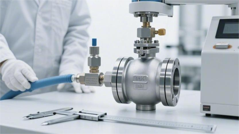
When purchasing industrial ball valves, focus on verifying that the hydrostatic test reaches 1.5 times the design pressure, the pneumatic sealing test shows zero leakage, the sealing surface finish is controlled to ≤ Ra 0.8 μm, and critical dimensional tolerances are held within ±0.05 mm. The opening and closing torque and concentricity should also be rechecked under the API 598 inspection procedure to ensure stable installation. Pressure Testing Shell Strength Test If the metal contains shrinkage cavities or inclusions above Grade 2, those weak spots can rupture and leak as soon as the body is subjected to hydrostatic pressure at 1.5 times normal working pressure. During the test, the ball valve must be kept in a half-open position. Workers use heavy-duty blind flanges to seal both ends of the valve completely. Bolt tightening is also strictly specified. For example, when testing an 8-inch Class 300 carbon steel ball valve, alloy steel bolts are required, and a torque wrench is typically set between 600 and 800 N·m. Water is then filled into the valve cavity, and all trapped air must be fully vented. An air-release valve is installed at the highest point of the body, and clean water is introduced at a flow speed of 0.5 m/s. Only when the discharge at the vent stops producing bubbles is the valve considered completely filled. Even a small amount of trapped air can cause the pressure gauge needle to fluctuate and distort the test reading. The test water temperature cannot be too low or too high and is generally controlled between 5°C and 50°C. Below 5°C, steel becomes brittle. For stainless steel valves, purified water must be used, with chloride ion content kept below 50 ppm to prevent corrosion. Blind plugs / blind flanges: must meet the standard minimum thickness requirement Sealing O-rings: high-pressure fluororubber capable of withstanding 42 MPa maximum hydrostatic pressure Test water quality: high purity, with conductivity controlled within 20 μS/cm Low-temperature steel: must be conditioned at room temperature for 4 hours before pressure testing Once the pump starts, the pressure gauge needle begins to rise, but the pressurization rate cannot be too fast. It must not exceed 1.5 MPa per second. For a Class 600 ball valve rated for 10.0 MPa, the test pressure must be driven up to 15.0 MPa, and the entire pressurization process must last at least 10 seconds. If the pressure rises too abruptly, the bolts securing the bonnet can deform under the load. Only after the needle has stabilized completely at 15.0 MPa can the worker start timing the pressure hold period. The larger the valve size, the longer the observation period required. Below 2 inches: hold and observe for 15 seconds 2.5 to 6 inches: hold and observe for 60 seconds 8 to 12 inches: hold and observe for 120 seconds 14 inches and above: hold and observe for 300 seconds During this period, the inspector uses a high-intensity flashlight and a long-handled inspection mirror to examine the valve body from all angles. Any visible seepage, misting, or even the slightest “sweating” on the shell is enough to fail the valve. On sand-cast valves, special attention is paid to joints and riser areas, where wall thickness can sometimes be 12.5% thinner. There is also packing around the stem to prevent leakage. If it is not compressed properly, problems appear immediately. On high-pressure valves such as Class 900, hydrostatic testing at 22.5 MPa generates several tons of outward force. Even 1 mm of packing deformation can cause water droplets to emerge from the gland area. On large forged steel ball valves with 24-inch openings, the body cavity can hold several cubic meters of water, and filling plus pressurization alone can take most of a day. The pressure gauge is mounted at the highest point of the blind flange. Its dial must be at least 100 mm in diameter, and its accuracy class must meet Class 1.6. Pressure gauges cannot be chosen casually. The full-scale range must be between 1.5 and 4 times the test pressure. For a 15.0 MPa hydrostatic test, a 25.0 MPa gauge is appropriate, placing the needle in the most accurate central zone of the dial. Bonnet gasket edge: watch closely for hanging water droplets Shell corners and edges: apply white chalk dust; even slight dampness leaves a dark stain Packing gland: watch whether water slowly creeps upward in the gap Drain plug: check whether the threaded joint feels completely dry Grease injection valve: verify whether the check ball leaks under water pressure When the hold period ends, the worker slowly opens the relief valve and lets the high-pressure water drop at a controlled rate of 2.0 MPa per second. Natural draining is not enough, because water remains trapped in dead corners. A 0.6 MPa compressed air line is then connected to blow through the valve cavity for 3 to 5 minutes. Sealing Test Once the high-pressure hydrostatic shell test is complete, the sealing test begins immediately. The pump raises the pressure on one side of the valve cavity to 1.1 times the normal working pressure. For a Class 600 carbon steel ball valve rated at 10.0 MPa under ambient conditions, the test pressure is raised to 11.0 MPa. Under API 598, a 4-inch metal-seated ball valve is allowed to leak no more than 8 drops of water per minute. A sheet of white paper or a graduated glass beaker is placed underneath to collect leakage, and 1 mL of water is approximately equal to 16 drops. For soft-seated ball valves using PTFE, the requirement is much stricter. Under ISO 5208 Rate A, not a single drop of water is allowed to pass. The inspector shines a flashlight along the dry metal outlet for a full 2 minutes. If even the slightest trace of moisture is seen in the reflection, the valve must be disassembled and reworked. The hydrostatic sealing test is not the end of the process. A workshop compressor then feeds about 0.6 MPa of dry nitrogen into
What Causes Industrial Ball Valve Failure in Harsh Working Conditions | seal wear, pressure fluctuation, material mismatch
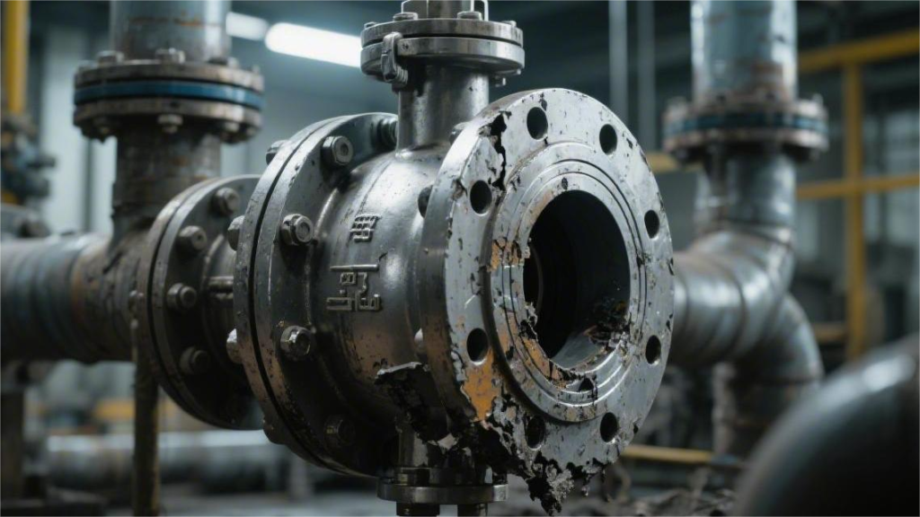
Industrial ball valves in severe service most often fail because seal wear exceeds 0.2 mm/year, pressure fluctuations go beyond ±20% of the design value, or materials are mismatched. In H₂S-containing service, for example, failing to use duplex stainless steel can sharply accelerate corrosion. During operation, torque variation should be monitored regularly; if it rises by 15% or more, the valve should undergo seal retesting in accordance with API 598 to prevent failure. Seal Wear Solid Particles In a 50 mm industrial pipeline, crude oil rushes through at 8.5 m/s. The fluid carries entrained particles, including quartz sand and rust flakes ranging from 15 microns to 2 mm. As the crude approaches a half-open ball valve, the flow area drops sharply from 1,960 mm² to less than 400 mm². The narrowed passage drives the flow velocity up to four times its original speed. The suspended quartz sand gains enormous kinetic energy. With a Mohs hardness of 7, these grains behave like miniature armor-piercing projectiles when they strike a soft plastic surface with a hardness of only Shore D55. Microscopic observation captures the force of impact. A single 0.5 mm sand particle, driven by a 3.2 MPa differential pressure, can instantly tear a groove 0.08 mm deep into an otherwise smooth surface. Common destructive particles found in pipelines include: Sharp quartz sand (hardness 7) Highly abrasive alumina powder (hardness 9) Large rust scale flakes (hardness 5 to 6) Crystalline salts prone to clogging (hardness 4) When fluid carrying hard solids flows through the valve, foreign matter is forcibly wedged between the ball and the seat. A gap of just 0.1 mm can result in a leakage rate of 45 liters per hour under a 2.0 MPa water pressure condition. The escaping fluid acts like a wire-cutting jet. Following the initial scratch, the high-speed stream erodes deeper along the damaged path, and a tiny 0.08 mm pit can expand into a 2.5 mm-wide deep groove within 48 hours. During valve actuation, particles attached to the ball surface are dragged into the sealing interface. As the ball rotates 90 degrees under a torque of 150 N·m, those particles cut into the surface like lathe tools. A natural gas master valve that had been in service for 120 days was dismantled for inspection. Its soft seat ring, originally 6.35 mm thick, had been abraded by sand and gravel until the thinnest section measured only 1.2 mm, with dense scratches deeper than 0.5 mm across the surface. These scratches destroy the protective barrier. Fine powder packs into the grooves and becomes compacted under pressure. As a result, the coefficient of friction rises dramatically from 0.04 at the factory to above 0.3. As friction multiplies, the air pressure required by the pneumatic actuator climbs from 0.4 MPa to 0.65 MPa. If the air supply becomes insufficient, the ball can stall in a half-open position at 45 degrees. A stalled ball then faces severe erosion. The fluid forms a jet at over 40 m/s, and the entrained metal fragments can pit a 316 stainless steel ball surface densely within just 3 minutes. Laboratory testing has quantified particle-related loss. In a slurry with a solids content of 3%, after 5,000 continuous operating cycles, conventional nylon components showed a mass loss rate of 18.5%. Service life under abrasive conditions varies significantly by material: Standard soft plastic parts: surface roughness fails after 24 hours Carbon-fiber-reinforced parts: grooves appear after 150 hours PEEK hard plastic: deformation reaches 5% after 300 hours Surface-hardened metal parts: maintain zero leakage for 1,200 hours A refinery catalytic cracking unit switched to a metal seat housing coated with tungsten carbide. The coating thickness was controlled at 0.2 to 0.3 mm, with a hardness of HV 1100. Under particle impact at the same flow velocity, the hardened surface showed only 0.005 mm micro-scratches. The high-speed sand particles rebounded on impact and were deflected toward the inner flow channel wall. Ultrasonic thickness inspections showed that in a water injection pipeline with a sand content of 5‰, a 12 mm carbon steel elbow wore down to the retirement threshold of 8.4 mm within 18 months. Installing a Y-strainer 1.5 meters upstream helps reduce the impact. A 40-mesh stainless steel screen with an aperture of about 0.4 mm can intercept large, hard particles. Increasing pipe diameter also reduces fluid velocity while maintaining the same flow rate of 200 m³/h. Expanding the diameter from 80 mm to 100 mm lowers the medium velocity from 11 m/s to 7 m/s. Lower velocity reduces kinetic energy on a square-law basis. When the speed falls to 63% of the original value, particle impact energy drops to 40%, and the wear rate decreases significantly. Equipment adjustments that help reduce fluid damage include: Installing a desander upstream to remove particles above 50 microns Increasing pipeline cross-sectional area to reduce initial fluid velocity Adjusting the pump inverter to lower supply pressure by 0.5 MPa Switching to a full-port design to minimize internal turbulence Even with filtration, micron-scale fine dust inevitably remains in the pipeline. These tiny crystals behave like polishing compound, settling silently along the contact line between the ball and the seat. With every rotation, a 0.01 mm layer of fine particles is compressed into the polymer structure. After six months of penetration, a white material can turn dark gray and become as brittle as cast iron. When such an embrittled component contracts under nighttime temperatures of -15°C, the internal stress can exceed its 15 MPa tensile limit. With an audible crack, a through-fracture as long as 40 mm can form. High-pressure gas at 6.0 MPa then escapes through a 0.2 mm crack. The violent vortex formed in the rear cavity can literally tear the entire seat assembly out of its retaining groove. Dry Friction & Torque Variation Pure high-pressure nitrogen flows continuously through a 4.0 MPa pipeline network. The automated control program requires the valve to open and close 800 times per day. Because the gas contains no moisture or oil at all, the polished
How Buyers Shortlist Ball Valve Manufacturers for New Projects | project fit, sample quality, certification readiness

When evaluating ball valve manufacturers, buyers first match the supplier’s offering to the project requirements, such as Class 300–1500 pressure ratings and service temperatures from -29°C to 425°C. They then assess sample performance against criteria including leakage within API 598 limits and opening/closing torque deviation within ±10%, while also confirming API 6D certification, ISO 9001 certification, and complete material traceability reports. In most cases, buyers compare 3–5 suppliers before selecting a qualified manufacturer. Project Fit Materials & Service Conditions Buyers start by reviewing the factory’s procurement records from the previous year, checking mill delivery notes line by line. What they are looking for is 2507 super duplex stainless steel. Its corrosion resistance rating, expressed as PREN, must exceed 40. Even a shortfall of 0.1 is enough for the entire heat of molten steel to be rejected and sent back to the mill. An inspector presses a handheld spectrometer firmly against a cut metal sample for 30 seconds. The display immediately shows the percentages of chromium, molybdenum, and nitrogen. A 24-inch valve body is then scanned with an ultrasonic flaw detector. If the image reveals even a 2 mm crack, the entire casting is rejected. Ferrite content must stay strictly between 35% and 55% Annealing temperature must be held at exactly 1040°C At -46°C, impact energy must still reach 45 J Weight loss in ferric chloride solution must not exceed 4 g At sour gas sites, field pipelines can contain hydrogen sulfide concentrations as high as 150,000 ppm. Ordinary steel can blister and crack apart within hours under those conditions. For this type of service, the specified material is often upgraded to costly C276 alloy. Where budgets are tighter, a layer of Inconel 625 is overlaid onto standard steel. The valve cavity is coated evenly with an acid-resistant protective layer at least 3 mm thick. A welder qualified to ASME Section IX works in full protective gear. Using GTAW, the welder slowly deposits the weld on the inner wall of the shell, which has been preheated to 150°C. A supervisor then checks the finished surface point by point with a calibrated gauge. The drawing requires a probe reading every 10 mm. If the instrument shows iron contamination above 5%, the entire area is ground out and welded again. Surface hardness must not exceed 22 HRC The surface is checked under a microscope for fine cracks Cooling curves are monitored after welding in a heat-retention enclosure Dye penetrant is used to check whether edge areas show bleed-out In coal preparation plants, the pipeline carries thick black slurry containing 30% hard coal ash, with operating temperatures reaching 450°C. A white PTFE seat exposed to that hot slurry can soften within seconds. In those workshops, all soft components are replaced with cast iron and hardened steel. Next to the machining table, a robotic arm turns and directs its spray gun at a polished steel ball. Fine tungsten carbide powder is driven forward by combustion gases. The powder strikes the steel surface at roughly Mach 2.5, forming an ultra-hard “armor” layer 0.3 mm thick. The coated parts are then moved into a furnace at 980°C and fired repeatedly until the coating becomes a fully bonded hard shell. After firing, two skilled technicians spend four full hours hand-lapping the ball and seat with 400-mesh diamond compound. The assembled unit is bolted together and connected to a thick hose charged with high-pressure nitrogen. An infrared camera watches continuously for leaks. If leakage stays below 0.0005 mL over one minute, the unit passes, and a V-grade leak-tightness label is printed immediately. Surface hardness exceeds 68 HRC Bond strength is greater than 70 MPa Ball surface finish is polished to 0.1 μm Sphericity tolerance is kept within 0.02 mm LNG tanks operate continuously at -196°C. Buyers therefore review how the 316L stainless components were treated for cryogenic service. Hundreds of metal pieces are loaded into stainless steel mesh baskets and immersed in liquid nitrogen for a full 24 hours. This extreme thermal cycling forces the internal structure into a more stable state, keeping shrinkage deformation below 0.15% once installed in cryogenic piping. Soft graphite packing is not permitted at the stem position. Instead, assemblers install a special PCTFE ring with a custom hex tool. Inside that ring is a U-shaped corrosion-resistant metal spring. No matter how low the outside temperature falls, the spring keeps constant pressure on the plastic ring to prevent leakage. A helium leak detector is then brought in. The inspector moves the suction probe slowly around the stem seal area. The scanning speed is kept at 10 mm per second. On the display, the leakage reading remains safely below the 100 ppm limit. Capacity & Lead Time For a 400 km gas transmission line, the requirement may be clear: 8,000 ball valves of various sizes must be delivered within six months. Buyers do not rely on sales claims alone. They count the machines themselves. On one side of the workshop are 45 CNC lathes with digital displays; on the other are 12 horizontal machining centers. They watch the cycle timers on the screens and use stopwatches to verify machining time per unit. For a standard 8-inch carbon steel body, the cutting tool may need 35 passes across the workpiece. Just keeping the spindle running for that job can consume 45 minutes. Some factories claim “10,000 units per month” in glossy brochures, but buyers want proof from the shop floor. Experienced buyers will go as far as checking three months of employee attendance records and comparing them against electricity bills from the utility provider. Two shifts rotate between day and night work Machines run 16 hours per day at full capacity Workers operate 6 days per week The plant stops for 3 maintenance days every month With those figures, a buyer can quickly calculate the factory’s true monthly output ceiling. Large-diameter valves slow everything down dramatically. At one crude oil terminal project, the urgent requirement was for several 48-inch pipeline ball valves. Each finished valve weighed
What Makes Ball Valve Manufacturers Competitive in Global Markets | product quality, pricing strategy, delivery reliability
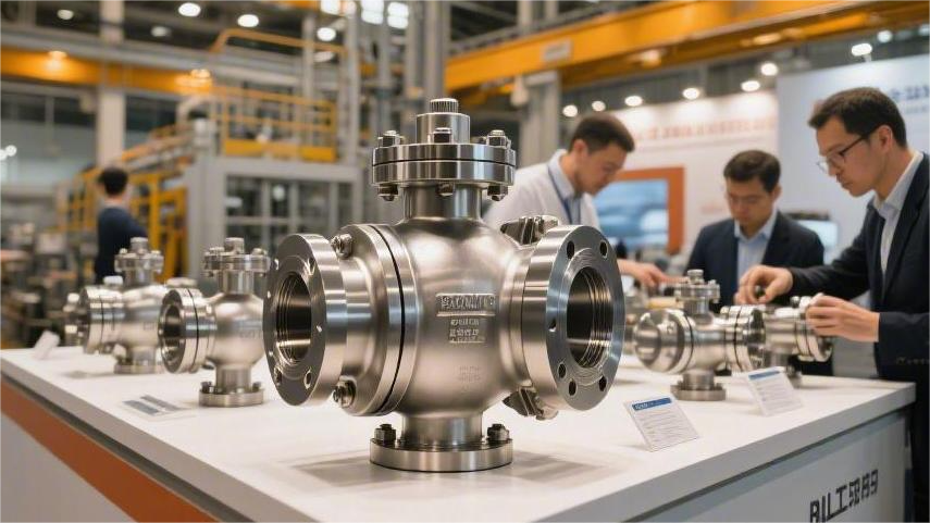
A ball valve manufacturer’s global competitiveness depends on maintaining a pass rate of at least 99%, pricing 5%–10% below comparable competitors, and keeping lead times within 30–45 days. It also requires API 6D certification, well-managed supply chain inventory with turnover within 60 days, and the use of CNC machining plus 100% air tightness testing to improve stability and customer confidence. Product Quality Corrosion Resistance & Pressure Endurance Oil pipelines operating 2,000 meters below sea level are exposed to 20 MPa of water pressure year-round, in seawater with a salinity above 3.5%. Drop an ordinary carbon steel valve into that environment, and in less than 72 hours it can corrode through under the attack of highly concentrated salt water. Many manufacturers use 2205 duplex stainless steel for the valve body. This steel contains 22% chromium, 5% nickel, and 3% molybdenum, with ferrite and austenite each accounting for half of its microstructure. Its pitting resistance equivalent number reaches 35, and its yield strength is roughly double that of standard 304 stainless steel. Even under prolonged exposure to high concentrations of chloride ions, the metal surface can resist pitting and localized attack. Different industrial pipelines carry highly corrosive fluids, forcing valve manufacturers to keep adjusting material formulas: Paper mill bleaching lines: 5% sodium hypochlorite at room temperature typically requires a titanium alloy body. Fertilizer plant synthesis zones: high-temperature ammonia solution at 190°C usually calls for 316L ultra-low-carbon stainless steel. Semiconductor cleaning workshops: 18 MΩ ultra-pure water systems require electropolished pipe walls. Offshore drilling platforms: continuous exposure to salt-laden sea air demands a 250-micron epoxy zinc-rich coating on the exterior. The metal body must withstand not only chemical attack from acids and alkalis, but also violent physical shock. In narrow pipelines, sudden opening and closing can trigger water hammer, generating impact forces three to four times higher than normal operating conditions. A ball valve rated for 10 MPa may perform routinely under standard pressure, but when a transient pressure spike hits, the internal pressure often surges to 30 MPa. Foundries send finished metal bodies into X-ray inspection rooms and use ultrasonic testing to detect tiny shrinkage cavities or gas porosity inside the casting. Even a microscopic pinhole left in an 8 mm-thick metal wall can, after three months of repeated 15 MPa pulsating pressure, grow into a major crack. Manufacturers strictly follow the wall-thickness requirements of ASME B16.34. For example, in a 2-inch Class 150 carbon steel ball valve, the thinnest section must never be less than 5.6 mm. When machining threads and flange faces, coaxial deviation is tightly controlled within 0.05 mm. Under extreme internal thrust, pressure-bearing components are pushed to their structural limits: Blowout-proof stem: designed with a larger base and smaller top so it cannot be forced out by pipeline pressure. Reinforced flange root: transition areas are formed with R5 to R10 radii to reduce fracture risk. High-strength fasteners: all bolts are upgraded to B7 alloy steel, with tensile strength above 860 MPa. Full-penetration welding: weld seams on large-diameter pipelines undergo 100% radiographic inspection. Conventional PTFE gaskets soften, deform, and get extruded from their grooves once pressure exceeds 4 MPa and the fluid temperature reaches 120°C. To solve this, workers blend 15%–25% glass fiber into the original Teflon powder and cure it at high temperature, tripling the gasket’s compressive strength. When service conditions exceed 25 MPa, even reinforced plastic gaskets fail almost instantly. At that point, manufacturers have no choice but to use metal-to-metal hard sealing, spraying tungsten carbide powder onto the ball and metal seat with supersonic flame. The hard alloy coating is applied to a thickness of 0.3 mm, with hardness measured above HRC 68. Every assembled valve is then moved to a pressure test bench. Operators seal both ends with heavy steel plates and fill the cavity with water mixed with rust inhibitor. A pneumatic pump gradually raises the pressure to 1.5 times the design pressure. A 4-inch Class 300 ball valve, for example, is held under 7.7 MPa of high-pressure water for a full 3 minutes, and not a single drop is allowed to leak. After the hydrostatic test, the water is drained and replaced with 0.6 MPa of dry compressed air. The entire valve is submerged in a clear water tank, and inspectors watch the stem and sealing areas closely for even the tiniest bubbles. For pipelines carrying toxic gases, leak detection must be done with a high-precision mass spectrometer. Even a helium leak as small as 10^-5 mbar·L/s can still be detected. Precision Manufacturing A 15 kg stainless steel forging fresh out of the furnace is covered with up to 2 mm of rough oxide scale. Before it can be installed on a chemical plant pipeline, it still has to go through more than a dozen extremely demanding machining steps. Ordinary lathes cannot handle alloys with hardness up to HB 200, so factories send them to heavy-duty CNC machining centers. Massive silicon carbide cutting tools strike the metal blank at 800 rpm, with sparks and water-soluble coolant flying everywhere. The first rough turning operation takes about 4 minutes, removing the outer 3 mm of excess material and roughly hollowing out the internal flow passage. Even after that step, the surface still has a height variation of 0.2 mm and feels rough to the touch. Whether a 15 MPa high-pressure water flow can be fully shut off depends entirely on how perfectly spherical the through-hole metal ball is. Engineers secure the semi-finished ball in a five-axis CNC machine and switch to extremely sharp polycrystalline diamond tools. During fine machining, the ball’s roundness error is strictly controlled within 0.005 mm. That 0.005 mm tolerance is roughly one-sixteenth the diameter of a human hair. If the operator’s hand slips slightly, or if the cutting tool wears by 0.01 mm, the ball may still appear acceptable—but once installed, highly penetrating natural gas can seep through nearly invisible gaps. Freshly machined metal balls are covered with fine tool marks about 0.8 microns deep, so they must be sent to
Best Ball Valve Manufacturers for Oil and Gas Applications | API standards, pressure class, material options
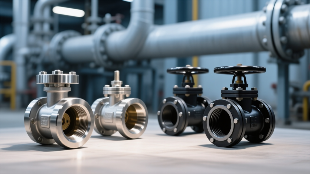
Ball valve manufacturers for oil and gas applications, such as Emerson and Flowserve, typically design to standards such as API 6D and API 608. Common pressure classes range from Class 150 to Class 2500, with upper limits approaching 1000 bar. Typical body materials include A105 carbon steel, 316L stainless steel, and duplex stainless steel. Material selection must match the medium and service conditions—for example, 2205 duplex stainless steel is often used for H₂S-containing media—while operating temperatures generally span from -50°C to 538°C. API 598 hydrostatic and sealing tests are then used to verify safety and reliability. API Standards API 6D API 6D requires a full-bore design, meaning the internal bore of the ball valve must match the pipeline bore. For a 48-inch Class 600 ball valve, for example, the seat bore is strictly specified at 1194 mm. A misalignment of even 2 mm can cause a pig, driven by dozens of tons of force, to slam into the seat and instantly shatter the PTFE sealing ring. In high-sulfur natural gas service, H₂S can easily penetrate ordinary carbon steel. When combined with moisture, hydrogen atoms accumulate within the metal and cause hydrogen-induced cracking. A350 LF2 forgings used in API 6D ball valves must therefore undergo full ultrasonic inspection before leaving the factory. Hardness is tightly controlled below 22 HRC to comply with NACE MR0175. Sulfur content in the steel must be reduced below 0.01%, and phosphorus must not exceed 0.02%. At -29°C, Charpy V-notch impact testing is mandatory. Each specimen must absorb no less than 20 joules. Internal metal and polymer components are also subject to strict material requirements: The stem uses 17-4PH precipitation-hardening stainless steel with a yield strength above 700 MPa. The ball surface is coated with tungsten carbide to a thickness of 0.15 to 0.2 mm. Springs are made from Inconel X-750 nickel alloy for stress-corrosion resistance. Seals use AED-resistant fluororubber to prevent explosive decompression damage under high-pressure gas. Bolts are ASTM A320 L7 alloy steel for low-temperature service. A 1°C rise in external temperature can generate roughly 10 MPa of pressure inside trapped liquid. Trunnion-mounted ball valves therefore include an internal cavity pressure relief design. When cavity pressure reaches 1.33 times line pressure, the spring-loaded seat automatically lifts, releasing the trapped pressure back into the pipeline so the center-flange bolts are not torn apart by hundreds of bar of internal force. Once the valve is fully closed, operators can open the drain port underneath to discharge any remaining oil. A DBB structure makes line draining significantly safer. Offshore drilling platforms often impose even stricter requirements and typically specify DIB-1 valve configurations. Both seats can withstand the force created by the double-piston effect, so even if one side fails, the other can still hold a differential pressure of up to 250 bar. Factory functional testing is also governed by fixed requirements: Fill the valve with water and pressurize it to 1.1 times the rated pressure. For 2-inch to 4-inch valves, the hold time is 2 minutes. For large ball valves over 18 inches, the hold time extends to 5 minutes. Leakage from the drain port must be zero. DIB testing requires reverse-direction high-pressure water to test each individual seat separately. API 6D also requires the anti-blowout stem design to be internal. When 15 MPa of pressure pushes outward from the pipeline, the internal shoulder locks the stem firmly against the thrust bearing. No matter what happens outside, the stem cannot be blown out by internal pressure and injure personnel. Valves that sit idle for months often require very high breakaway torque on first operation, so actuators are typically oversized by a factor of 1.5 to 2. Take an NPS 36 Class 900 trunnion-mounted ball valve as an example. The factory test torque is specified at 80,000 N·m. Its pneumatic actuator can deliver 150,000 N·m of torque. The adjacent control cabinet contains a 500-liter high-pressure air tank, with enough stored energy to perform three consecutive operations—open, close, then open again. The flange bolts on the valve body must not only contain the internal pressure but also withstand bending moments of several hundred kilonewtons caused by thermal expansion and contraction of the pipeline. A fully welded ball valve eliminates the center flange entirely, with the body closed by two submerged arc welds. These welds are fully radiographed and evaluated to ASME BPVC Section VIII. For buried service, the exterior is coated with a 1.5 to 2.5 mm polyurethane anti-corrosion layer. Inspectors then use a 15,000-volt holiday detector to scan the coating and identify pinhole-sized defects. API 608 When installing metal ball valves in process piping, workers must purchase them to API 608. The standard covers sizes from as small as 1/4 inch up to 24 inches. Pressure classes are limited to Class 150, Class 300, and Class 600. The base ASME B16.34 standard does not provide enough protection for highly corrosive chemical service. API 608 adds a mandatory 2.5 mm corrosion allowance on top of the original wall-thickness formula. On a 2-inch Class 300 carbon steel valve, for example, the body wall thickness must never be less than 8.6 mm. At the stockyard, inspectors use handheld spectrometers to verify incoming material: WCB carbon steel must contain less than 0.30% carbon. CF8M stainless steel contains 2.0% molybdenum. Forged material must have a forging reduction ratio of 3:1. Ultrasonic testing must be able to detect internal cracks as small as 2 mm. Machinists turn a 3 mm shoulder disk at the bottom of the stem. Even if all gland bolts fail, 10 MPa of heavy oil inside the line still cannot blow out a stem designed with anti-blowout retention. With a one-meter lever, the required operating force must not exceed 360 N. On gear-operated valves, the rim force at the handwheel must remain under 80 N. If the measured value even slightly exceeds the limit, the entire gearbox is dismantled and sent back to the workshop for re-gearing. Class 300 ball valves larger than 4 inches use a heavy bottom shaft
